Neamen D. Microelectronics: Circuit Analysis and Design
Подождите немного. Документ загружается.


578 Part 1 Semiconductor Devices and Basic Applications
Crossover distortion can be virtually eliminated by biasing both Q
n
and Q
p
with
a small quiescent collector current when
v
I
is zero. This technique is discussed in the
next section. The crossover distortion effect can also be minimized with an op-amp
used in a feedback configuration. Op-amps are discussed in Chapter 9 and feedback
is discussed in Chapter 12, so this technique is not discussed here.
EXAMPLE 8.5
Objective: Determine the total harmonic distortion (THD) of the class B comple-
mentary push–pull output stage in Figure 8.19.
A PSpice analysis was performed, which yielded the harmonic content of the
output signal.
Solution: A 1 kHz sinusoidal signal with an amplitude of 2 V was applied to the
input of the circuit shown in Figure 8.19. The circuit was biased at
±
10 V. The
transistors used in the circuit were 2N3904 npn and 2N3906 pnp devices. A 1 k
load was connected to the output.
The harmonic content for the first nine harmonics is shown in Table 8.3. We see
that the output is rich in odd harmonics with the 3 kHz third harmonic being 18 per-
cent as large as the 1 kHz principal output signal. The total harmonic distortion is
19.7 percent, which is large.
Table 8.3 Harmonic content for Example 8.5
Normalized
Frequency (Hz) Fourier component component Phase (degrees)
1.000E+03 1.151E+00 1.000E+00 -1.626E-01
2.000E+03 6.313E-03 5.485E-03 -9.322E+01
3.000E+03 2.103E-01 1.827E-01 -1.793E+02
4.000E+03 4.984E-03 4.331E-03 -9.728E+01
5.000E+03 8.064E-02 7.006E-02 -1.792E+02
6.000E+03 3.456E-03 3.003E-03 -9.702E+01
7.000E+03 2.835E-02 2.464E-02 1.770E+02
8.000E+03 2.019E-03 1.754E-03 -8.029E+01
9.000E+03 6.679E-03 5.803E-03 1.472E+02
TOTAL HARMONIC DISTORTION = 1.974899E+01 PERCENT
Comment: These results show the obvious effects of the dead band region. If the
input signal amplitude increases, the total harmonic distortion decreases, but if the
amplitude decreases, the total harmonic distortion will increase above the 19 percent
value.
EXERCISE PROBLEM
*Ex 8.5: Repeat Example 8.5 for the case when an NMOS transistor replaces the
npn transistor and a PMOS transistor replaces the pnp transistor in Figure 8.19.
nea80644_ch08_559-614.qxd 06/15/2009 01:31 PM Page 578 F506 Hard disk:Desktop Folder:ALI:MHDQ134-08 Folder:MHDQ134-08:
Chapter 8 Output Stages and Power Amplifiers 579
Idealized Power Efficiency
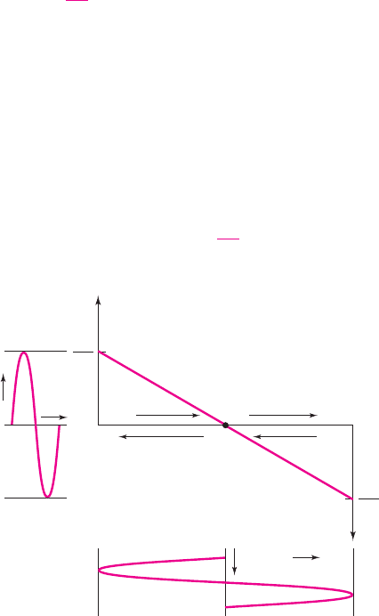
If we consider an idealized version of the circuit in Figure 8.19 in which the
base–emitter turn-on voltages are zero, then each transistor would conduct for
exactly one-half cycle of the sinusoidal input signal. This circuit would be an ideal
class-B output stage, and the output voltage and load current would be replicas of the
input signal. The collector–emitter voltages would also show the same sinusoidal
variation.
Figure 8.22 illustrates the applicable dc load line. The Q-point is at zero collec-
tor current, or at cutoff for both transistors. The quiescent power dissipation in each
transistor is then zero.
The output voltage for this idealized class-B output stage can be written
v
O
= V
p
sin ωt
(8.16)
where the maximum possible value of V
p
is V
CC
.
The instantaneous power dissipation in Q
n
is
p
Qn
= v
CEn
i
Cn
(8.17)
and the collector current is
i
Cn
=
V
p
R
L
sin ωt
(8.18(a))
for
0 ≤ ωt ≤ π
, and
i
Cn
= 0
(8.18(b))
for
π ≤ ωt ≤ 2π
, where V
p
is the peak output voltage.
From Figure 8.22, we see that the collector–emitter voltage can be written as
v
CEn
= V
CC
− V
p
sin ωt
(8.19)
Therefore, the total instantaneous power dissipation in Q
n
is
p
Qn
= (V
CC
− V
p
sin ωt)
V
p
R
L
sin ωt
(8.20)
i
Cn
i
Cp
V
CC
2V
CC
v
CEn
0
0
Q
n
conducting
Q
p
conducting
Time
Time
0
0
V
CC
R
L
V
C
C
R
L
v
O
i
L
v
ECP
V
CC
2V
CC
Figure 8.22 Effective load line of the ideal class-B output stage
nea80644_ch08_559-614.qxd 06/15/2009 01:31 PM Page 579 F506 Hard disk:Desktop Folder:ALI:MHDQ134-08 Folder:MHDQ134-08:
580 Part 1 Semiconductor Devices and Basic Applications
for
0 ≤ ωt ≤ π
, and
p
Qn
= 0
for
π ≤ ωt ≤ 2π
. The average power dissipation is therefore
¯
P
Qn
=
V
CC
V
p
π R
L
−
V
2
p
4R
L
(8.21)
The average power dissipation in transistor Q
p
is exactly the same as that for Q
n
,
because of symmetry.
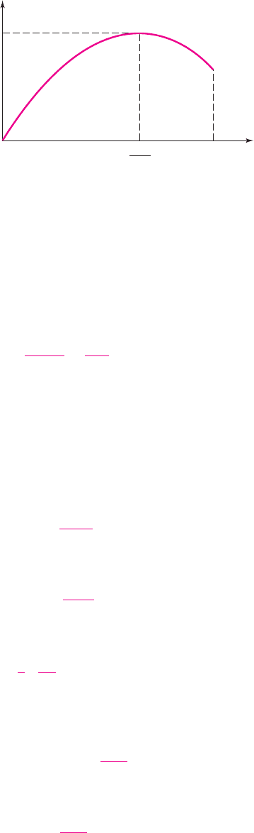
A plot of the average power dissipation in each transistor, as a function of V
p
,is
shown in Figure 8.23. The power dissipation first increases with increasing output
voltage, reaches a maximum, and finally decreases with increasing V
p
. We determine
the maximum average power dissipation by setting the derivative of
¯
P
Qn
with respect
to V
p
equal to zero, producing
¯
P
Qn
(max) =
V
2
CC
π
2
R
L
(8.22)
which occurs when
V
p
¯
P
Qn
(max)
=
2V
CC
π
(8.23)
The average power delivered to the load is
¯
P
L
=
1
2
·
V
2
p
R
L
(8.24)
Since the current supplied by each power supply is half a sine wave, the average
current is V
p
/(πR
L
). The average power supplied by each source is therefore
¯
P
S+
=
¯
P
S−
= V
CC
V
p
π R
L
(8.25)
and the total average power supplied by the two sources is
¯
P
S
= 2V
CC
V
p
π R
L
(8.26)
P
–
Qn
P
–
Qn
(max)
V
P
V
CC
0
2V
CC
π
Figure 8.23 Average power dissipation in each transistor versus peak output voltage for
class-B output stage
nea80644_ch08_559-614.qxd 06/15/2009 01:31 PM Page 580 F506 Hard disk:Desktop Folder:ALI:MHDQ134-08 Folder:MHDQ134-08:

Chapter 8 Output Stages and Power Amplifiers 581
From Equation (8.12), the conversion efficiency is
η =
1
2
·
V
2
p
R
L
2V
CC
V
p
π R
L
=
π
4
·
V
p
V
CC
(8.27)
The maximum possible efficiency, which occurs when
V
p
= V
CC
,is
η(max) =
π
4
⇒ 78.5%
(8.28)
This maximum efficiency value is substantially larger than that of the standard
class-A amplifier.
From Equation (8.24), we find the maximum possible average power that can be
delivered to the load, as follows:
¯
P
L
(max) =
1
2
·
V
2
CC
R
L
(8.29)
The actual conversion efficiency obtained in practice is less than the maximum
value because of other circuit losses, and because the peak output voltage must
remain less than V
CC
to avoid transistor saturation. As the output voltage amplitude
increases, output signal distortion also increases. To limit this distortion to an
acceptable level, the peak output voltage is usually limited to several volts below
V
CC
. From Figure 8.23 and Equation (8.23), we see that the maximum transistor
power dissipation occurs when
V
p
= 2V
CC
/π
. At this peak output voltage, the con-
version efficiency of the class-B amplifier is, from Equation (8.27),
η =
π
4V
CC
· V
p
=
π
4V
CC
·
2V
CC
π
=
1
2
⇒ 50%
(8.30)
Class-AB Operation
Crossover distortion can be virtually eliminated by applying a small quiescent bias
on each output transistor, for a zero input signal. This is called a class-AB output
stage and is shown schematically in the circuit in Figure 8.24. If Q
n
and Q
p
are
matched, then for
v
I
= 0, V
BB
/2
is applied to the B–E junction of Q
n
, V
BB
/2 is
applied to the E–B junction of Q
p
, and
v
O
= 0
. The quiescent collector currents in
each transistor are given by
i
Cn
= i
Cp
= I
S
e
V
BB
/2V
T
(8.31)
As
v
I
increases, the voltage at the base of Q
n
increases and
v
O
increases. Tran-
sistor Q
n
operates as an emitter follower, supplying the load current to R
L
. The out-
put voltage is given by
v
O
= v
I
+
V
BB
2
−v
BEn
(8.32)
and the collector current of Q
n
(neglecting base currents) is
i
Cn
= i
L
+i
Cp
(8.33)
Since i
Cn
must increase to supply the load current,
v
BEn
increases. Assuming
V
BB
remains constant, as
v
BEn
increases,
v
EBp
decreases resulting in a decrease in i
Cp
.
8.3.3
nea80644_ch08_559-614.qxd 06/15/2009 01:31 PM Page 581 F506 Hard disk:Desktop Folder:ALI:MHDQ134-08 Folder:MHDQ134-08:
582 Part 1 Semiconductor Devices and Basic Applications
As
v
I
goes negative, the voltage at the base of Q
p
decreases and
v
O
decreases.
Transistor Q
p
operates as an emitter follower, sinking current from the load. As i
Cp
increases,
v
EBp
increases, causing a decrease in
v
BEn
and i
Cn
.
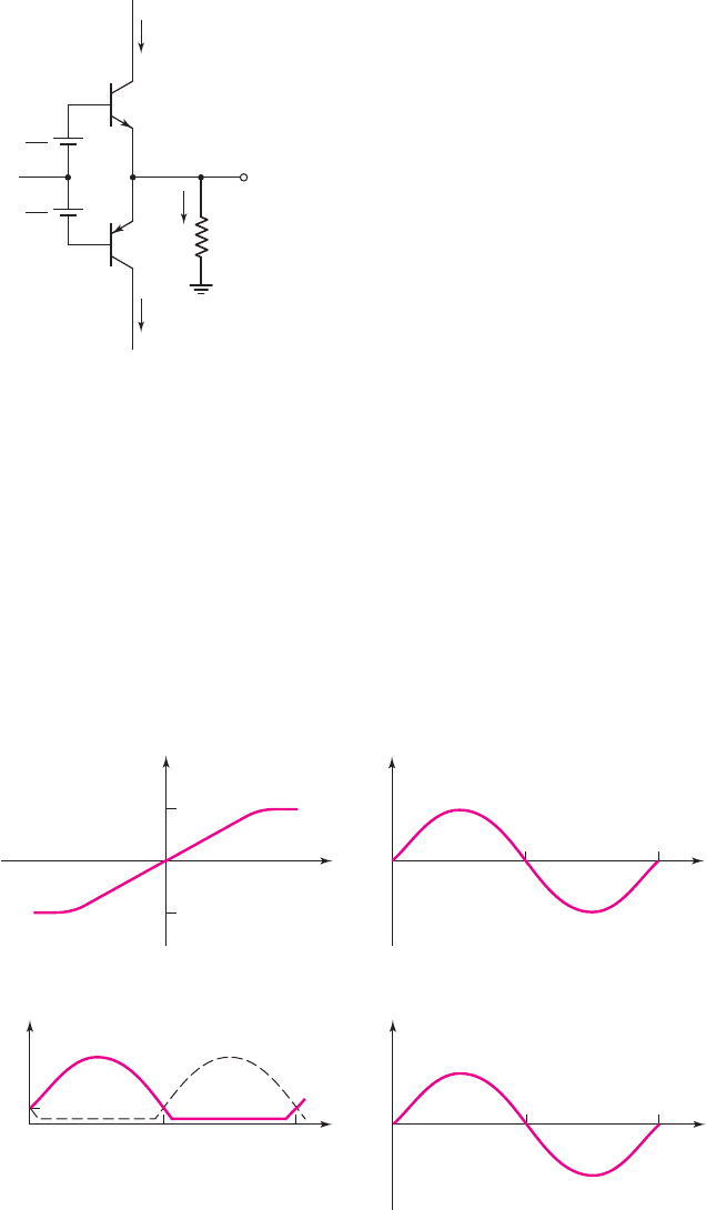
Figure 8.25(a) shows the voltage transfer characteristics for this class-AB output
stage. If
v
BEn
and
v
EBp
do not change significantly, then the voltage gain, or the
slope of the transfer curve, is essentially unity. A sinusoidal input signal voltage and
the resulting collector currents and load current are shown in Figures 8.25(b), (c), and
(d). Each transistor conducts for more than one-half cycle, which is the definition of
class-AB operation.
(c)
(d)
p
2p
i
L
0
i
C
i
Cn
I
CQ
i
Cp
p
2p
0
(a)
v
O
v
I
(V
CC
– V
CE
(sat))
–(V
CC
– V
EC
(sat))
Slope ≈ 1
(b)
v
I
0
p
2p
w t
w t
w t
Figure 8.25 Characteristics of a class-AB output stage: (a) voltage transfer curve,
(b) sinusoidal input signal, (c) collector currents, and (d) output current
+V
CC
–V
CC
Q
n
Q
p
v
O
v
I
R
L
V
BB
2
V
BB
2
i
Cn
i
Cp
i
L
Figure 8.24 Bipolar class-AB output stage
nea80644_ch08_559-614.qxd 06/15/2009 01:31 PM Page 582 F506 Hard disk:Desktop Folder:ALI:MHDQ134-08 Folder:MHDQ134-08:

Chapter 8 Output Stages and Power Amplifiers 583
There is a relationship between i
Cn
and i
Cp
. We know that
v
BEn
+v
EBp
= V
BB
(8.34(a))
which can be written
V
T
ln
i
Cn
I
S
+ V
T
ln
i
Cp
I
S
= 2V
T
ln
I
CQ
I
S
(8.34(b))
Combining terms in Equation (8.34(b)), we find
i
Cn
i
Cp
= I
2
CQ
(8.35)
The product of i
Cn
and
i
Cp
is a constant; therefore, if
i
Cn
increases,
i
Cp
decreases, but
does not go to zero.
Since, for a zero input signal, quiescent collector currents exist in the output
transistors, the average power supplied by each source and the average power
dissipated in each transistor are larger than for a class-B configuration. This means
that the power conversion efficiency for a class-AB output stage is less than that for
an idealized class-B circuit. In addition, the required power handling capability of
the transistors in a class-AB circuit must be slightly larger than in a class-B circuit.
However, since the quiescent collector currents I
CQ
are usually small compared to the
peak current, this increase in power dissipation is not great. The advantage of elimi-
nating crossover distortion in the class-AB output stage greatly outweighs the slight
disadvantage of reduced conversion efficiency and increased power dissipation.
EXAMPLE 8.6
Objective: Determine the total harmonic distortion (THD) of the class AB comple-
mentary push–pull output stage shown in Figure 8.24.
A PSpice analysis was performed, which yielded the harmonic content of the
output signal.
Solution: A 1 kHz sinusoidal signal with an amplitude of 2 V was applied to the
input of the circuit. The bias voltages V
BB
/2 were varied. The circuit was biased at
±10
V and a 1 k load was connected to the output. Shown in Table 8.4 are the
V
BB
/2 bias voltages applied, the quiescent transistor currents, and the total harmonic
distortion (THD).
Table 8.4 Quiescent collector currents and total
harmonic distortion of class-AB circuit
V
BB
/2 (V) I
CQ
(mA) THD (%)
0.60 0.048 1.22
0.65 0.33 0.244
0.70 2.20 0.0068
0.75 13.3 0.0028
Discussion: With a peak input voltage of 2 V and a 1 k load, the peak load current
is on the order of 2 mA. From the results shown in Table 8.4, the THD decreases as
the ratio of quiescent transistor current to peak load current increases. In other words,
for a given input voltage, the smaller the variation in collector current when the
nea80644_ch08_559-614.qxd 06/15/2009 01:31 PM Page 583 F506 Hard disk:Desktop Folder:ALI:MHDQ134-08 Folder:MHDQ134-08:
584 Part 1 Semiconductor Devices and Basic Applications
signal is applied compared to the quiescent collector current, the smaller the distor-
tion. However, there is a trade-off. As the quiescent transistor current increases, the
power efficiency is reduced. The circuit should be designed such that the transistor
quiescent current is the smallest value while meeting the maximum total harmonic
distortion specification.
Comment: We see that the class-AB output stage results in a much smaller THD
value than the class-B circuit, but as with most circuits, there are no uniquely speci-
fied bias voltages.
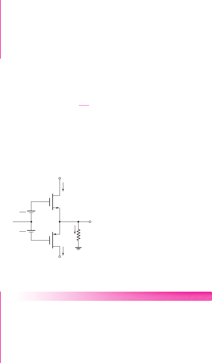
A class-AB output stage using enhancement-mode MOSFETs is shown in Fig-
ure 8.26. If M
n
and M
p
are matched, and if
v
I
= 0
, then
V
BB
/2
is applied across the
gate–source terminals of M
n
and the source–gate terminals of M
p
. The quiescent
drain currents established in each transistor are given by
i
Dn
= i
Dp
= I
DQ
= K
V
BB
2
−
|
V
T
|
2
(8.36)
As
v
I
increases, the voltage at the gate of M
n
increases and
v
O
increases. Transis-
tor M
n
operates as a source follower, supplying the load current to R
L
. Since i
Dn
must
increase to supply the load current,
v
GSn
must also increase. Assuming V
BB
remains
constant, an increase in v
GSn
implies a decrease in
v
SGp
and a resulting decrease in
i
Dp
. As
v
I
goes negative, the voltage at the base of M
p
decreases and
v
O
decreases.
Transistor M
p
then operates as a source follower, sinking current from the load.
+V
DD
–V
DD
v
O
v
I
R
L
V
BB
2
V
BB
2
+
–
v
GSn
+
–
v
SGp
M
n
M
p
i
Dn
i
Dp
i
L
Figure 8.26 MOSFET class-AB output stage
EXAMPLE 8.7
Objective: Determine the required biasing in a MOSFET class-AB output stage.
The circuit is shown in Figure 8.26. The parameters are
V
DD
= 10
V and
R
L
=
20 . The transistors are matched, and the parameters are
K = 0.20
A/V
2
and
|
V
T
|
= 1V
. The quiescent drain current is to be 20 percent of the load current when
v
O
= 5
V.
Solution: For
v
O
= 5
V,
i
L
= 5/20 = 0.25 A
nea80644_ch08_559-614.qxd 06/15/2009 01:31 PM Page 584 F506 Hard disk:Desktop Folder:ALI:MHDQ134-08 Folder:MHDQ134-08:

Chapter 8 Output Stages and Power Amplifiers 585
Then, for
I
Q
= 0.05
A when
v
O
= 0
, we have
I
DQ
= 0.05 = K
V
BB
2
−
|
V
T
|
2
= (0.20)
V
BB
2
−1
2
which yields
V
BB
/2 = 1.50 V
The input voltage for
v
O
positive is
v
I
= v
O
+v
GSn
−
V
BB
2
For
v
O
= 5
V and
i
Dn
∼
=
i
L
= 0.25 A
, we have
v
GSn
=
i
Dn
K
+
|
V
T
|
=
0.25
0.20
+1 = 2.12 V
The source-to-gate voltage of M
p
is
v
SGp
= V
BB
− V
GSn
= 3 −2.12 = 0.88 V
which means that M
p
is cut off and
i
Dn
= i
L
. Finally, the input voltage is
v
I
= 5 +2.12 −1.5 = 5.62 V
Comment: Since
v
I
>v
O
, the voltage gain of this output stage is less than unity, as
expected.
EXERCISE PROBLEM
Ex 8.7: Consider the MOSFET class-AB output stage shown in Figure 8.26. The
circuit parameters are
V
DD
= 15
V and
R
L
= 25
. The transistors are matched
with parameters
K = 0.25 A/V
2
and
|
V
T
|
= 1.2
V. The quiescent drain currents
are to be 20 percent of the load current when
v
O
= 8
V. (a) Determine
V
BB
and
(b) find the small-signal voltage gain
A
v
= dv
O
/dv
I
at (i)
v
O
= 0
and
(ii)
v
O
= 8
V. (Ans. (a)
V
BB
= 3.412
V; (b) (i)
A
v
= 0.927
, (ii)
A
v
= 0.934)
Voltage
V
BB
can be established in a MOSFET class-AB circuit by using addi-
tional enhancement-mode MOSFETs and a constant current I
Bias
. This will be con-
sidered in a problem at the end of the chapter.
Class-C Operation
The transistor circuit ac load line, including an extension beyond cutoff, is shown in
Figure 8.27. For class-C operation, the transistor has a reverse-biased B–E voltage
at the Q-point. This effect is illustrated in Figure 8.27. Note that the collector cur-
rent is not negative, but is zero at the quiescent point. The transistor conducts only
when the input signal becomes sufficiently positive during its positive half-cycle.
The transistor therefore conducts for less than a half-cycle, which defines class-C
operation.
Class-C amplifiers are capable of providing large amounts of power, with con-
version efficiencies larger than 78.5 percent. These amplifiers are normally used for
radio-frequency (RF) circuits, with tuned RLC loads that are commonly used in radio
8.3.4
nea80644_ch08_559-614.qxd 06/15/2009 01:31 PM Page 585 F506 Hard disk:Desktop Folder:ALI:MHDQ134-08 Folder:MHDQ134-08:

586 Part 1 Semiconductor Devices and Basic Applications
and television transmitters. The RLC circuits convert drive current pulses into sinu-
soidal signals. Since this is a specialized area, we will not analyze these circuits here.
Test Your Understanding
TYU 8.4 For the common-emitter output stage shown in Figure 8.16(a), let
V
CC
= 12
V and
R
L
= 1
k
. Assume the transistor
Q
-point is in the center of the
load line. (a) Determine the quiescent power dissipated in the transistor. (b) Assume
the sinusoidal output voltage is limited to a 9 V peak-to-peak value. Determine (i) the
average signal power delivered to the load, (ii) the power conversion efficiency,
and (iii) the average power dissipated in the transistor. (Ans. (a)
P
Q
= 36
mW;
(b) (i)
P
L
= 10.1
mW, (ii)
η = 14.1%
, (iii)
P
Q
= 25.9
mW)
TYU 8.5 Design an idealized class-B output stage, as shown in Figure 8.18, to
deliver an average of 25 W to an 8 speaker. The peak output voltage must be no
larger than 80 percent of supply voltages V
CC
. Determine: (a) the required value of
V
CC
, (b) the peak current in each transistor, (c) the average power dissipated in
each transistor, and (d) the power conversion efficiency. (Ans. (a)
V
CC
= 25
V
(b)
I
p
= 2.5
A (c)
¯
P
Q
= 7.4W
(d)
η = 62.8%
)
TYU 8.6 For the idealized class-B output stage shown in Figure 8.18, the parameters
are
V
CC
= 5
V and
R
L
= 100
. The measured output signal is
v
o
= 4 sin ωt
(V).
Determine: (a) the average signal load power, (b) the peak current in each transistor,
(c) the average power dissipated in each transistor, and (d) the power conversion ef-
ficiency. (Ans. (a)
¯
P
L
= 80 mW
(b)
I
p
= 40
mA (c)
¯
P
Q
= 23.7mW
(d)
η = 62.8%
)
8.4 CLASS-A POWER AMPLIFIERS
Objective: • Analyze several circuit configurations of class-A power
amplifiers.
The standard class-A amplifier was analyzed previously, and the maximum possible
power conversion efficiency was found to be 25 percent. This conversion efficiency
can be increased with the use of inductors and transformers.
i
C
v
CE
v
BE
signal
00
00
i
C
0
AC load line
extended
Q-point
(negative V
BEQ
)
p
p
w t
w t
Figure 8.27 Effective ac load line of a class-C amplifier
nea80644_ch08_559-614.qxd 06/15/2009 01:31 PM Page 586 F506 Hard disk:Desktop Folder:ALI:MHDQ134-08 Folder:MHDQ134-08:

Chapter 8 Output Stages and Power Amplifiers 587
Inductively Coupled Amplifier
Delivering a large power to a load generally requires both a large voltage and a high
current. In a common-emitter circuit, this requirement can be met by replacing
the collector resistor with an inductor, as shown in Figure 8.28(a). The inductor is a
short circuit to a dc current, but acts as an open circuit to an ac signal operating at a
sufficiently high frequency. The entire ac current is therefore coupled to the load. We
assume that
ωL R
L
at the lowest signal frequency.
The dc and ac load lines are shown in Figure 8.28(b). We assume that the resis-
tance of the inductor is negligible, and that the emitter resistor value is small. The
quiescent collector–emitter voltage is then approximately
V
CEQ
∼
=
V
CC
. The ac
collector current is
i
c
=
−v
ce
R
L
(8.37)
To obtain the maximum symmetrical output-signal swing, which will in turn
produce the maximum power, we want
I
CQ
∼
=
V
CC
R
L
(8.38)
For this condition, the ac load line intersects the
v
CE
axis at
2V
CC
.
The use of an inductor or storage device results in an output ac voltage swing
that is larger than
V
CC
. The polarity of the induced voltage across the inductor may be
such that the voltage adds to
V
CC
, producing an output voltage that is larger than
V
CC
.
The absolute maximum amplitude of the signal current in the load is
I
CQ
; there-
fore, the maximum possible average signal power delivered to the load is
¯
P
L
(max) =
1
2
I
2
CQ
R
L
=
1
2
·
V
2
CC
R
L
(8.39)
If we neglect the power dissipation in the bias resistors R
1
and R
2
, the average power
supplied by the V
CC
source is
¯
P
S
= V
CC
I
CQ
=
V
2
CC
R
L
(8.40)
8.4.1
(a)
(b)
C
C1
→ ∞
C
C2
→ ∞
C
E
→ ∞
v
i
v
o
V
CC
R
2
R
E
R
L
R
1
L
+
–
i
L
R
i
v
CE
V
CC
I
CQ
i
C
2V
CC
DC load line, slope = –
2V
CC
R
L
1
R
E
AC load line, slope = –
1
R
L
Figure 8.28 (a) Inductively coupled class-A amplifier and (b) dc and ac load lines
nea80644_ch08_559-614.qxd 06/15/2009 01:31 PM Page 587 F506 Hard disk:Desktop Folder:ALI:MHDQ134-08 Folder:MHDQ134-08: