Neamen D. Microelectronics: Circuit Analysis and Design
Подождите немного. Документ загружается.

688 Part 2 Analog Electronics
v
O
v
I
R
C
C
E
I
O
V
+
V
–
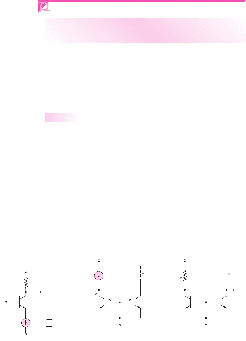
Figure 10.1 Bipolar circuit with
ideal current-source biasing
10.1 BIPOLAR TRANSISTOR CURRENT SOURCES
Objective: • Analyze and understand the characteristics of various
bipolar circuits used to provide a constant output current.
As we saw in previous chapters, when the bipolar transistor is used as a linear
amplifying device, it must be biased in the forward-active mode. The bias may be a
current source that establishes the quiescent collector current as shown in Fig-
ure 10.1. We now need to consider the types of circuits that can be designed to
establish the bias current I
O
. We will discuss a simple two-transistor current-source
circuit and then two improved versions of the constant-current source. We will then
analyze another current-source circuit, known as the Widlar current source. Finally,
we will discuss a multitransistor current source.
Two-Transistor Current Source
The two-transistor current source, also called a current mirror, is the basic build-
ing block in the design of integrated circuit current sources. Figure 10.2(a) shows the
basic current-source circuit, which consists of two matched or identical transistors,
Q
1
and Q
2
, operating at the same temperature, with their base terminals and emitter
terminals connected together. The B–E voltage is therefore the same in the two
transistors. Transistor Q
1
is connected as a diode; consequently, when the supply
voltages are applied, the B–E junction of
Q
1
is forward biased and a reference
current I
REF
is established. Although there is a specific relationship between I
REF
and
V
BE1
, we can think of V
BE1
as being the result of I
REF
. Once
V
BE1
is established, it is
applied to the B–E junction of Q
2
. The applied
V
BE2
turns Q
2
on and generates the
load current I
O
, which is used to bias a transistor or transistor circuit.
The reference current in the two-transistor current source can be established by
connecting a resistor to the positive voltage source, as shown in Figure 10.2(b). The
reference current is then
I
REF
=
V
+
− V
BE
− V
−
R
1
(10.1)
10.1.1
I
C2
= I
O
I
C1
I
B1
I
B2
I
REF
+
–
V
CE2
+
–
V
BE2
+
–
V
BE1
Q
2
Q
1
V
+
V
–
(a) (b)
V
C2
+
–
V
BE
I
C2
= I
O
I
REF
Q
2
Q
1
R
1
V
+
V
–
Figure 10.2 (a) Basic two-transistor current source; (b) two-transistor
current source with reference resistor R
1
nea80644_ch10_687-752.qxd 6/19/09 4:27 AM Page 688 pmath DATA-DISK:Desktop Folder:18.6.09:MHDQ134-10:

Chapter 10 Integrated Circuit Biasing and Active Loads 689
1
In actual circuits, the collector–emitter voltage may decrease to values as low as 0.2 or 0.3 V, and the
circuit will still behave as a constant-current source.
where
V
BE
is the B–E voltage corresponding to the collector current, which is es-
sentially equal to I
REF
.
Connecting the base and collector terminals of a bipolar transistor effectively
produces a two-terminal device with I–V characteristics that are identical to the i
C
versus
v
BE
characteristic of the BJT. For
v
CB
= 0
, the transistor is still biased in the
forward-active mode, and the base, collector, and emitter currents are related through
the current gain β. In constant-current source circuits, β is a dc term that is the ratio
of the dc collector current to the dc base current. However, as discussed in Chapter 5,
we assume the dc leakage currents are negligible; therefore, the dc beta and ac beta
are essentially the same. We do not distinguish between the two values.
Current Relationships
Figure 10.2(a) shows the currents in the two-transistor current source. Since V
BE
is the same in both devices, and the transistors are identical, then I
B1
=
I
B2
and I
C1
=
I
C2
.
Transistor Q
2
is assumed to be biased in the forward-active region. If we sum the cur-
rents at the collector node of Q
1
, we have
I
REF
= I
C1
+ I
B1
+ I
B2
= I
C1
+2I
B2
(10.2)
Replacing I
C1
by I
C2
and noting that
I
B2
= I
C2
/β
, Equation (10.2) becomes
I
REF
= I
C2
+2
I
C2
β
= I
C2
1 +
2
β
(10.3)
The output current is then
I
C2
= I
O
=
I
REF
1 +
2
β
(10.4)
Equation (10.4) gives the ideal output current of the two-transistor current
source, taking into account the finite current gain of the transistors. Implicit in Equa-
tion (10.4) is that Q
2
is biased in the forward-active region (the base–collector junc-
tion is zero or reverse biased, meaning
V
CE2
> V
BE2
1
) and the Early voltage is
infinite, or
V
A
=∞
. We will consider the effects of a finite Early voltage later in this
chapter.
DESIGN EXAMPLE 10.1
Objective: Design a two-transistor current source to meet a set of specifications.
Specifications: The circuit to be designed has the configuration shown in Fig-
ure 10.2(b).Assume that matched transistors are available with parameters
V
BE
(on) =
0.6 V,
β = 100
, and
V
A
=∞
. The designed output I
O
is to be 200 μA. The bias volt-
ages are to be
V
+
= 5
V and
V
−
= 0
.
Choices: The circuit will be fabricated as an integrated circuit so that a standard
resistor value is not required and matched transistors can be fabricated.
nea80644_ch10_687-752.qxd 6/19/09 4:27 AM Page 689 pmath DATA-DISK:Desktop Folder:18.6.09:MHDQ134-10:

690 Part 2 Analog Electronics
Solution: The reference current can be written as
I
REF
= I
O
1 +
2
β
= (200)
1 +
2
100
= 204 μA
From Equation (10.1), the resistor R
1
is found to be
R
1
=
V
+
− V
BE
(on)
I
REF
=
5 − 0.6
0.204
= 21.6k
Trade-offs: The design assumes that matched transistors exist. The effect of mis-
matched transistors will be discussed later in this section.
Comment: In this example, we assumed a B–E voltage of 0.6 V. This approximation
is satisfactory for most cases. The B–E voltage is involved in the reference current or
resistor calculation. If a value of
V
BE
(on)
=
0.7 V is assumed, the value of I
REF
or R
1
will change, typically, by only 1 to 2 percent.
Design Pointer: We see in this example that, for
β = 100
, the reference and load
currents are within 2 percent of each other in this two-transistor current source. In
most circuit applications, we can use the approximation that
I
O
∼
=
I
REF
.
EXERCISE PROBLEM
Ex 10.1: The circuit parameters for the two-transistor current source shown in
Figure 10.2(b) are
V
+
= 3
V,
V
−
=−3
V, and
R
1
= 47
k
. The transistor para-
meters are
β = 120
,
V
BE
(
on
)
= 0.7
V, and
V
A
=∞
. Determine
I
REF
,
I
O
, and
I
B1
.
(Ans.
I
REF
= 0.1128
mA,
I
O
= 0.1109
mA,
I
B1
= 0.9243 μ
A)
Output Resistance
In our previous analysis, we assumed the Early voltage was infinite, so that
r
O
=∞
.
In actual transistors, the Early voltage is finite, which means that the collector current
is a function of the collector–emitter voltage. The stability of a load current generated
in a constant-current source is a function of the output resistance looking back into
the output transistor.
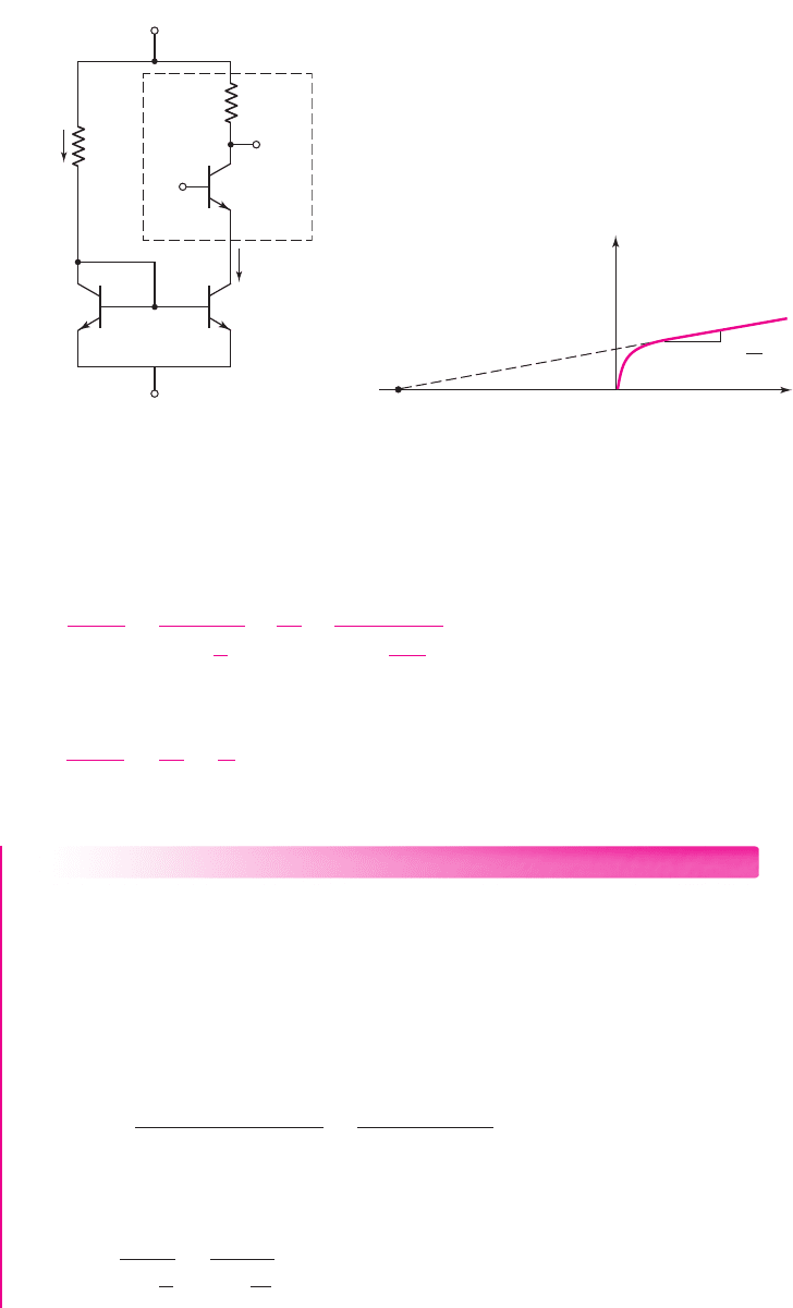
Figure 10.3 shows the dc equivalent circuit of a simple transistor circuit biased
with a two-transistor current source. The voltage V
I
applied to the base of Q
o
is a dc
voltage. If the value of V
I
changes, the collector–emitter voltage
V
CE2
changes since
the B–E voltage of Q
o
is essentially a constant. A variation in
V
CE2
in turn changes
the output current I
O
, because of the Early effect. Figure 10.4 shows that I
O
versus
V
CE2
characteristic at a constant B–E voltage.
The ratio of load current to reference current, taking the Early effect into
account, is
I
O
I
REF
=
1
1 +
2
β
×
1 +
V
CE2
V
A
1 +
V
CE1
V
A
(10.5)
where V
A
is the Early voltage and the factor (
1 + 2/β
) accounts for the finite gain.
From the circuit configuration, we see that
V
CE1
= V
BE
, which is essentially a
constant, and
V
CE2
= V
I
− V
BEo
− V
−
(10.6)
nea80644_ch10_687-752.qxd 6/19/09 4:27 AM Page 690 pmath DATA-DISK:Desktop Folder:18.6.09:MHDQ134-10:
Chapter 10 Integrated Circuit Biasing and Active Loads 691
I
REF
I
O
R
C
R
1
Q
1
Q
2
Q
o
+
–
V
CE1
+
–
V
CE2
+
–
V
BE
+
–
V
BEo
V
O
V
I
Load
circuit
V
+
V
–
Figure 10.3 The dc equivalent circuit
of simple amplifier biased with two-
transistor current source
I
O
V
CE2
–V
A
V
BE2
= constant
Slope =
0
1
r
o
Figure 10.4 Output current versus collector–emitter
voltage, showing the Early voltage
The differential change in I
O
with respect to a change in
V
CE2
, is, from Equa-
tion (10.5),
dI
O
dV
CE2
=
I
REF
1 +
2
β
×
1
V
A
×
1
1 +
V
BE
V
A
(10.7)
If we assume
V
BE
V
A
, then Equation (10.7) becomes
dI
O
dV
CE2
∼
=
I
O
V
A
=
1
r
o
(10.8)
where r
o
is the small-signal output resistance looking into the collector of Q
2
.
EXAMPLE 10.2
Objective: Determine the change in load current produced by a change in collector–
emitter voltage in a two-transistor current source.
Consider the circuit shown in Figure 10.3. The circuit parameters are:
V
+
= 5
V,
V
−
=−5
V, and
R
1
= 9.3k
. Assume the transistor parameters are:
β = 50
,
V
BE
(on) = 0.7
V, and
V
A
= 80
V. Determine the change in I
O
as
V
CE2
changes from 0.7 V to 5 V.
Solution: The reference current is
I
REF
=
V
+
− V
BE
(on) − V
−
R
1
=
5 − 0.7 −(−5)
9.3
= 1.0mA
For
V
CE2
= 0.7
V, transistors Q
1
and Q
2
are identically biased. From Equation (10.5),
we then have
I
O
=
I
REF
1 +
2
β
=
1.0
1 +
2
50
= 0.962 mA
nea80644_ch10_687-752.qxd 6/19/09 4:27 AM Page 691 pmath DATA-DISK:Desktop Folder:18.6.09:MHDQ134-10:

692 Part 2 Analog Electronics
From Equation (10.8), the small-signal output resistance is
r
o
=
V
A
I
O
=
80
0.962
= 83.2k
The change in load current is determined from
dI
O
dV
CE2
=
1
r
o
or
dI
O
=
1
r
o
dV
CE2
=
1
83.2
(5 − 0.7) = 0.052 mA
The percent change in output current is therefore
dI
O
I
O
=
0.052
0.962
= 0.054 ⇒ 5.4%
Comment: Although in many circuits a 5 percent change in bias current is insigni-
ficant, there are cases, such as digital-to-analog converters, in which the bias current
must be held to very tight tolerances. The stability of the load current can be signifi-
cantly affected by a change in collector–emitter voltage. The stability is a function of
the output impedance of the current source.
EXERCISE PROBLEM
Ex 10.2: Consider the circuit shown in Figure 10.3. The circuit parameters are:
V
+
= 5
V,
V
−
=−5
V, and
R
1
= 12 k
. The transistor parameters are
β = 75
and
V
BE
(on) = 0.7
V. The percentage change in load current
I
O
/I
O
must be no
more than 2 percent for a change in
V
CE2
from 1 V to 5 V. Determine the mini-
mum required value of Early voltage. (Ans.
V
A
∼
=
200
V)
Integrated Circuit Fabrication
We have assumed in the previous analysis that the two transistors in the current source
circuit are matched or identical. When fabricated as an integrated circuit, the two tran-
sistors will be directly adjacent to each other. The material properties will therefore be
essentially identical, and any ion implant dose and thermal anneal characteristics will
be essentially identical. So, the two adjacent transistors can be very well matched.
There may be some variation in transistor characteristics from one circuit to another
but, again, the characteristics of the adjacent transistors are closely matched. In prac-
tice, the characteristics of Q
1
and Q
2
may be mismatched by 1 or 2 percent.
Mismatched Transistors
If
β 1
, we can neglect base currents. The current–voltage relationship for the
circuit in Figure 10.2(b) is then
I
REF
∼
=
I
C1
= I
S1
e
V
BE
/V
T
(10.9(a))
and
I
O
= I
C2
= I
S2
e
V
BE
/V
T
(10.9(b))
nea80644_ch10_687-752.qxd 6/19/09 4:27 AM Page 692 pmath DATA-DISK:Desktop Folder:18.6.09:MHDQ134-10:
Chapter 10 Integrated Circuit Biasing and Active Loads 693
Here, we are neglecting the Early effect. The parameters I
S1
and I
S2
contain both the
electrical and geometric parameters of Q
1
and Q
2
. If Q
1
and Q
2
are not identical, then
I
S1
= I
S2
.
Combining Equations (10.9(a)) and (10.9(b)), we obtain the relationship between
the bias and reference currents, neglecting base currents, as follows:
I
O
= I
REF
I
S2
I
S1
(10.10)
Any deviation in bias current from the ideal, as a function of mismatch between Q
1
and Q
2
, is directly related to the ratio of the reverse-saturation currents I
S1
and I
S2
.
The parameter I
S
is a strong function of temperature. The temperatures of Q
1
and Q
2
must be the same in order for the circuit to operate properly. Therefore, Q
1
and
Q
2
must be close to one another on the semiconductor chip. If Q
1
and Q
2
are not
maintained at the same temperature, then the relationship between I
O
and I
REF
is a
function of temperature, which is undesirable.
Also, the parameters I
S1
and I
S2
are functions of the cross-sectional area of the
B–E junctions. Therefore, we can use Equation (10.10) to our advantage. By using
different sizes of transistors, we can design the circuit such that
I
O
= I
REF
. This is
discussed further later in this chapter.
Integrated circuit resistors are a function of the resistivity of the semiconductor
material as well as the geometry of the device. Since the geometry of each IC resis-
tor can be individually designed, resistor values are not limited to standard values.
So, IC resistors of any value (within reason) can be fabricated.
Improved Current-Source Circuits
In many IC designs, critical current-source characteristics are the changes in bias
current with variations in
β
and with changes in the output transistor collector volt-
age. In this section, we will look at two constant-current circuits that have improved
load current stability against changes in
β
and changes in output collector voltage.
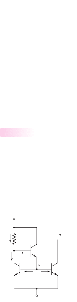
Basic Three-Transistor Current Source
A basic three-transistor current source is shown in Figure 10.5. We again assume that
all transistors are identical; therefore, since the B–E voltage is the same for Q
1
and
10.1.2
I
C2
= I
O
I
C1
I
B2
I
B3
I
E3
I
B1
I
REF
Q
1
Q
3
R
1
Q
2
+
–
V
BE
+
–
V
BE3
V
+
V
–
Figure 10.5 Basic three-transistor current source
nea80644_ch10_687-752.qxd 6/19/09 4:27 AM Page 693 pmath DATA-DISK:Desktop Folder:18.6.09:MHDQ134-10:

694 Part 2 Analog Electronics
Q
2
,
I
B1
= I
B2
and
I
C1
= I
C2
. Transistor Q
3
supplies the base currents to Q
1
and Q
2
,
so these base currents should be less dependent on the reference current. Also, since
the current in Q
3
is substantially smaller than that in either Q
1
or Q
2
, we expect the
current gain of Q
3
to be less than those of Q
1
and Q
2
. We define the current gains of
Q
1
and Q
2
as
β
1
= β
2
≡ β
, and the current gain of Q
3
as
β
3
. Summing the currents
at the collector node of Q
1
, we obtain
I
REF
= I
C1
+ I
B3
(10.11)
Since
I
B1
= I
B2
= 2I
B2
= I
E3
(10.12)
and
I
E3
= (1 +β
3
)I
B3
(10.13)
then combining Equations (10.11), (10.12), and (10.13) produces
I
REF
= I
C1
+
I
E3
(1 + β
3
)
= I
C1
+
2I
B2
(1 + β
3
)
(10.14)
Replacing I
C1
by I
C2
and noting that
I
B2
= I
C2
/β
, we can rewrite Equa-
tion (10.14) as
I
REF
= I
C2
+
2I
C2
β(1 +β
3
)
= I
C2
1 +
2
β(1 +β
3
)
(10.15)
The output or bias current is then
I
C2
= I
O
=
I
REF
1 +
2
β(1 +β
3
)
(10.16)
The reference current is given by
I
REF
=
V
+
− V
BE3
− V
BE
− V
−
R
1
∼
=
V
+
−2V
BE
− V
−
R
1
(10.17)
As a first approximation, we usually assume that the B–E voltage of Q
3
and Q
1
are
equal, as indicated in Equation (10.17).
A comparison of Equation (10.16) for the three-transistor current source and
Equation (10.4) for the two-transistor current source shows that the approximation of
I
O
∼
=
I
REF
is better for the three-transistor circuit. In addition, as we will see in the
following example, the change in load current with a change in
β
is much smaller in
the three-transistor current source.
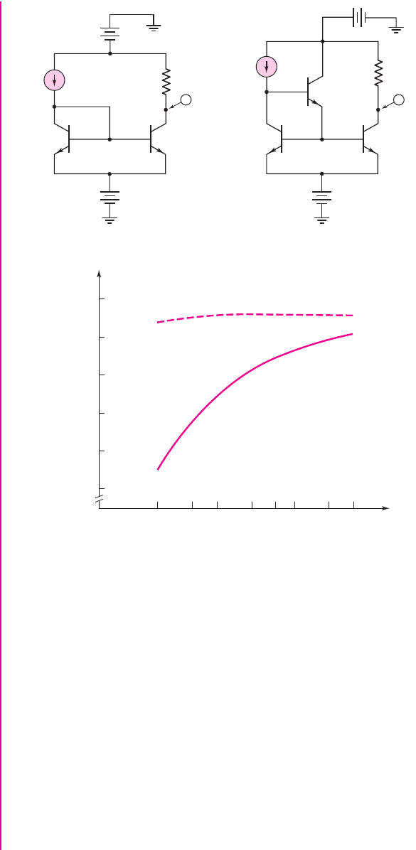
EXAMPLE 10.3
Objective: Compare the variation in bias current between the two- and three-transistor
current-source circuits as a result of variations in
β
. A PSpice analysis is used.
Figure 10.6(a) shows the two-transistor PSpice circuit schematic and Fig-
ure 10.6(b) shows the three-transistor PSpice circuit schematic used in this analysis.
nea80644_ch10_687-752.qxd 6/19/09 4:27 AM Page 694 pmath DATA-DISK:Desktop Folder:18.6.09:MHDQ134-10:
Chapter 10 Integrated Circuit Biasing and Active Loads 695
Solution:
In both circuits, the current gain β of all transistors was assumed to be
equal, but the actual value was varied between 20 and 200. Since the change in β is
very large, we cannot use derivatives to determine the changes in bias currents. Stan-
dard 2N3904 transistors were used, which means that the Early voltage is 74 V, and
not infinite as in the ideal circuit. The Early voltage will influence the actual value of
bias current, but has very little effect in terms of the change in bias current with a
change in current gain.
Figure 10.6(c) shows the bias current versus current gain for both the two-
transistor and three-transistor current-source circuits.
Comment: There is a significant decrease in the variation in bias current for the
three-transistor circuit compared to that of the two-transistor circuit. For values of
β
greater than approximately 50, there is no perceptible change in bias current for the
three-transistor current mirror.
0.90
20 30 40 60 80 100 150 200
0.92
0.94
0.96
0.98
1.00
I
O
(mA)
3-transistor
circuit
2-transistor
circuit
b f
(c)
V
1
V
1
V
2
V
2
I
1
I
1
R
1
I
dc
Q
1
2N3904
Q
2
2N3904
Q
3
2N3904
Q
2
2N3904
Q
1
2N3904
R
1
–5 V
–5 V
5 V
–5 V
1 mA
I
dc
1 mA
9.3 kΩ
9.3 kΩ
I
I
0
0
0
0
–
+
–
+
–
+
–
+
(a) (b)
Figure 10.6 (a) Two-transistor current mirror; (b) three-transistor current mirror;
(c) variation in bias currents with a change in
β
nea80644_ch10_687-752.qxd 6/19/09 4:27 AM Page 695 pmath DATA-DISK:Desktop Folder:18.6.09:MHDQ134-10:
696 Part 2 Analog Electronics
EXERCISE PROBLEM
Ex 10.3: The parameters of the circuit shown in Figure 10.5 are:
V
+
= 3
V,
V
−
=−3
V, and
R
1
= 30
k
. The parameters of the transistors
Q
1
and
Q
2
are
V
BE1,2
(
on
)
= 0.7
V and
β = 120
. The parameters of the transistor
Q
3
are
V
BE3
(
on
)
= 0.6
V and
β
3
= 80
. Assume
V
A
=∞
for all three transistors. Deter-
mine the value of each current shown in the figure. (Ans.
I
REF
= 0.15667
mA,
I
O
= 0.15663
mA
= I
C1
= I
C2
,
I
B1
= I
B2
= 1.3053 μ
A,
I
E3
= 2.6106 μ
A,
I
B3
= 0.03223 μ
A)
The output resistance looking into the collector of the output transistor Q
2
of the
basic three-transistor current source shown in Figure 10.5 is the same as that of the
two-transistor current source; that is,
dI
O
dV
CE2
=
1
r
o2
(10.18a)
where
r
o2
=
V
A
I
O
(10.18b)
This means that, in the three-transistor current source, the change in bias current I
O
with a change in V
CE2
is the same as that in the two-transistor current-source circuit.
In addition, any mismatch between Q
1
and Q
2
produces a deviation in the bias
current from the ideal, as given by Equation (10.10).
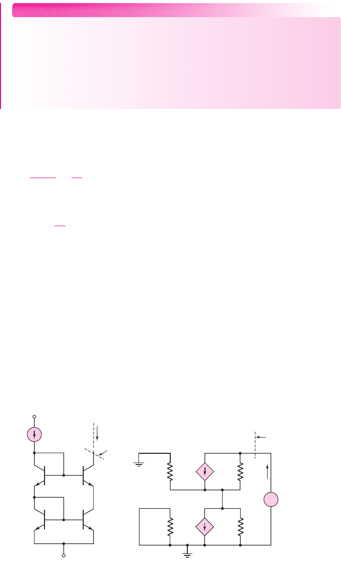
Cascode Current Source
Current-source circuits can be designed such that the output resistance is much
greater than that of the two-transistor circuit. One example is the cascode circuit
shown in Figure 10.7(a). In this case, if the transistors are matched, then the load and
reference currents are essentially equal.
We may calculate the output resistance R
o
by considering the small-signal
equivalent transistor circuits. For a constant reference current, the base voltages
of Q
2
and Q
4
are constant, which implies these terminals are at signal ground.
I
REF
Q
3
Q
1
Q
2
Q
4
V
BE2
V
BE4
+
–
+
–
I
O
R
o
V
+
V
–
0 =
V
be4
V
be2
I
x
g
m4
V
be4
g
m2
V
be2
r
o 4
r
o 2
r
p 4
r
p 2
+
–
+
–
R
o
V
x
+
–
(a) (b)
Figure 10.7 (a) Bipolar cascode current mirror; (b) small-signal equivalent circuit
nea80644_ch10_687-752.qxd 6/19/09 4:27 AM Page 696 pmath DATA-DISK:Desktop Folder:18.6.09:MHDQ134-10:
Chapter 10 Integrated Circuit Biasing and Active Loads 697
The equivalent circuit is then shown in Figure 10.7(b). Since
g
m2
V
be2
= 0
, then
V
be4
=−I
x
(r
o2
r
π4
)
. Summing currents at the output node yields
I
x
= g
m4
V
be4
+
V
x
− I
x
(r
o2
r
π4
)
r
o4
=−g
m4
I
x
(r
o2
r
π4
) +
V
x
− I
x
(r
o2
r
π4
)
r
o4
(10.19)
Combining terms and assuming
r
π4
r
o2
, we find
R
o
=
V
x
I
x
= r
o4
(1 + β) +r
π4
∼
=
βr
o4
(10.20)
The output resistance has increased by a factor of β compared to the two-transistor
current source, which increases the stability of the current source with changes in
output voltage.
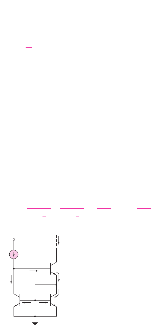
Wilson Current Source
Another configuration of a three-transistor current source, called a Wilson current
source, is shown in Figure 10.8. This circuit also has a large output resistance. Our
analysis again assumes identical transistors, with
I
B1
= I
B2
and
I
C1
= I
C2
. The
current levels in all three transistors are nearly the same; therefore, we can assume
that the current gains of the three transistors are equal. Nodal equations at the collec-
tor of Q
1
and the emitter of Q
3
yield
I
REF
= I
C1
+ I
B3
(10.21)
and
I
E3
= I
C2
+2I
B2
= I
C2
1 +
2
β
(10.22)
Using the relationships between the base, collector, and emitter currents in Q
3
, we
can write the collector current I
C2
, from Equation (10.22), as follows:
I
C2
=
I
E3
1 +
2
β
=
1
1 +
2
β
×
1 + β
β
I
C3
=
1 + β
2 + β
I
C3
(10.23)
I
REF
Q
1
V
+
Q
2
I
C3
= I
O
I
C1
I
C2
I
B2
I
B3
I
E3
I
B1
Q
3
Figure 10.8 Wilson current source
nea80644_ch10_687-752.qxd 6/19/09 4:27 AM Page 697 pmath DATA-DISK:Desktop Folder:18.6.09:MHDQ134-10: