Neamen D. Microelectronics: Circuit Analysis and Design
Подождите немного. Документ загружается.

748 Part 2 Analog Electronics
Section 10.3 Active Load Circuits
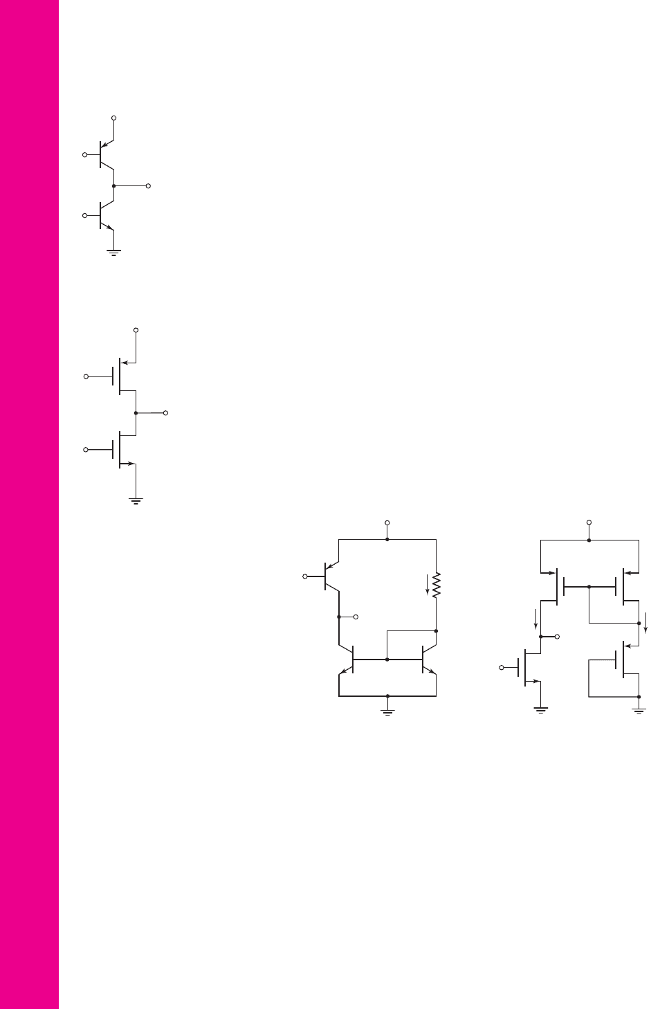
10.75 Consider the circuit shown in Figure P10.75. The transistor parameters are
I
S1
= 5 ×10
−16
A,
I
S2
= 10
−15
A,
β
1
= 180
,
β
2
= 120
,
V
A1
= 120
V, and
V
A2
= 80
V. The
Q
-point is
V
O
= 1.25
V and
I
CQ
= 200 μ
A. (a) Deter-
mine the small-signal voltage gain, (b) determine
V
I
, and (c) determine
V
B
.
10.76 For the circuit shown in Figure P10.76, the transistor parameters are
V
TN
= 0.5
V,
V
TP
=−0.5
V,
k
n
= 100 μ
A/V
2
,
k
p
= 60 μ
A/V
2
,
λ
1
=
0.02
V
−1
, and
λ
2
= 0.03
V
−1
. The quiescent drain current is
I
DQ
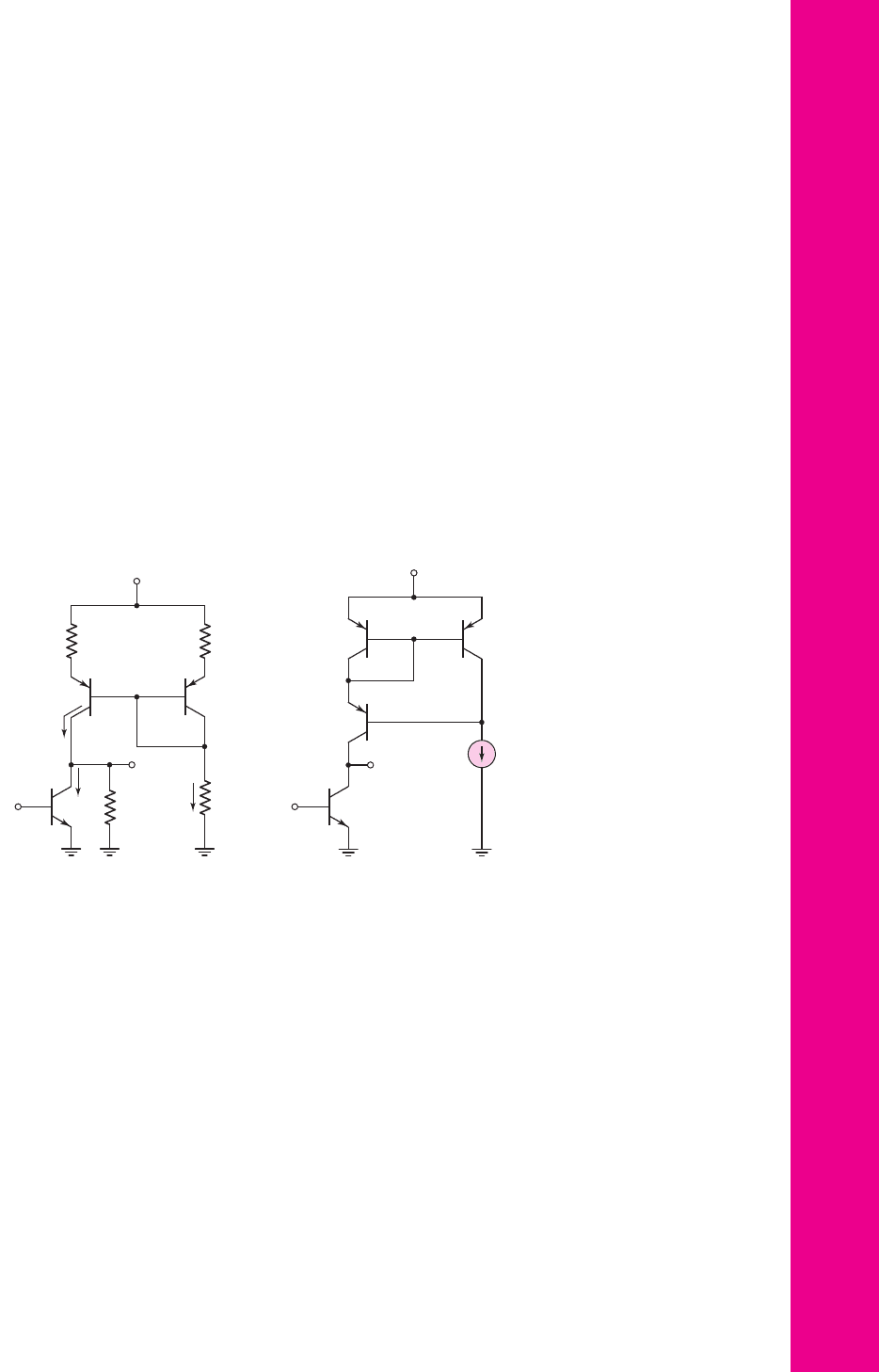
= 200 μ
A
and the quiescent output voltage is
V
O
= 1.25
V. (a) Determine
(
W/L
)
1
such that the small-signal voltage gain is
A
v
=−100
, (b) determine
V
I
,
and (c) determine
V
G
assuming
K
n1
= K
p2
.
10.77 Consider the simple BJT active load amplifier in Figure 10.29, with transistor
parameters:
I
SO
= 10
−12
A,
I
S1
= I
S2
= 5 ×10
−13
A,
V
AN
= 120
V,
and
V
AP
= 80
V. Let
V
+
= 5
V, and neglect base currents. (a) Find the
value of V
EB
that will produce
I
REF
= 1
mA. (b) Determine the value of
R
1
. (c) What value of V
I
will produce
V
CEO
= V
EC2
? (d) Determine the
open-circuit small-signal voltage gain.
10.78 The amplifier shown in Figure P10.78 uses a pnp driver and an npn active
load circuit. The transistor parameters are:
I
S0
= 5 ×10
−13
A,
I
S1
= I
S2
=
10
−12
A,
V
AN
= 120
V, and
V
AP
= 80
V. Let
V
+
= 5
V, and neglect base
currents. (a) Find the value of V
BE
that will produce
I
REF
= 0.5
mA.
(b) Determine the value of R
1
. (c) What value of V
I
will produce
V
EC0
= V
CE2
? (d) Determine the open-circuit small-signal voltage gain.
Q
2
Q
1
V
I
V
O
V
B
V
+
= 2.5 V
Figure P10.75
Figure P10.76
V
+
= 2.5 V
M
2
M
1
V
O
V
G
V
I
D10.79 The bias voltage of the MOSFET amplifier with active load in Figure
P10.79 is changed to
V
+
= 3
V. The transistor parameters are
V
TN
=
0.5V
V,
V
TP
=−0.5
V,
k
n
= 100 μ
A/V
2
,
k
p
= 60 μ
A/V
2
, and
λ
n
= λ
p
=
0.02
V
−1
. The quiescent values are
V
O
= 1.5
V and
V
I
= 1.2
V. (a) Design
the circuit
W/L
ratios, such that
I
REF
= I
O
= 100 μ
A. Assume
M
1
and
M
2
are matched. (b) Determine the small-signal voltage gain.
10.80 The simple MOSFET amplifier with active load shown in Figure 10.33 is
biased at
V
+
= 3
V. The reference current is
I
REF
= 80 μ
A. The transistor
parameters are
V
TN
= 0.5
V,
V
TP
=−0.5
V,
K
n
= K
p
= 0.1
mA, and
λ
n
= λ
p
= 0.02
V
−1
. (a) Find
V
SG
. (b) What value of
V
I
will produce
V
DSO
= V
SD2
? (c) Determine the small-signal voltage gain.
R
1
Q
1
Q
2
v
I
V
+
+
–
V
BE
Q
0
v
O
I
REF
Figure P10.78
V
+
= 5 V
I
REF
I
O
v
I
v
O
M
1
M
3
M
2
M
o
+
–
V
SG
Figure P10.79
nea80644_ch10_687-752.qxd 6/19/09 4:28 AM Page 748 pmath DATA-DISK:Desktop Folder:18.6.09:MHDQ134-10:
Chapter 10 Integrated Circuit Biasing and Active Loads 749
Section 10.4 Small-Signal Analysis: Active Load Circuits
10.81 Consider the circuit shown in Figure 10.37(a). Let
V
+
= 3
V and
R
1
=
47
k
. The transistors
Q
1
and
Q
2
are matched with
V
EB
(on) = 0.6
V.
Neglect base currents, and assume
V
AP
= 90
V and
V
AN
= 120
V. Deter-
mine the small-signal voltage gain for (a)
R
L
=∞
, (b)
R
L
= 300
k
, and
(c)
R
L
= 150
k
.
10.82 Again consider the circuit shown in Figure 10.37(a). Let
V
+
= 5
V and
R
1
= 35 k
. Let
V
EB1
(on) = 0.6
V. Neglect dc base currents. The base-
emitter area of Q
2
is twice that of Q
1
. The Early voltages are
V
AN
= 120
V
and
V
AP
= 80
V. Determine the small-signal voltage gain for (a)
R
L
=∞
and (b)
R
L
= 250 k
.
10.83 A BJT amplifier with active load is shown in Figure P10.83. The cir-
cuit contains emitter resistors R
E
and a load resistor R
L
. (a) Derive the
expression for the output resistance looking into the collector of Q
2
.
(b) Using the small-signal equivalent circuit, derive the equation for the
small-signal voltage gain. Express the relationship in a form similar to
Equation (10.94).
10.84 In the circuit in Figure P10.84, the active load circuit is replaced by a
Wilson current source. Assume that
β = 80
for all transistors, and that
V
AN
= 120
V,
V
AP
= 80
V, and
I
REF
= 0.2
mA. Determine the open-
circuit small-signal voltage gain.
10.85 For the circuit in Figure 10.40(a), the transistor parameters are
k
n
=
80
μ
A/V
2
,
k
p
= 40
μA/V
2
,
V
TN
= 0.8
V,
V
TP
=−0.6
V,
λ
n
= 0.015
V
−1
,
and
λ
p
= 0.02 V
−1
. Also, assume
(W/L)
o
= 20
and
(W/L)
1
=
(W/L)
2
= 35
. The circuit parameters are
V
+
= 5
V and
I
REF
= 200 μ
A.
(a) Determine the g
m
and r
o
parameters of each transistor. (b) Determine
the open-circuit small-signal voltage gain. (c) Determine the value of R
L
that results in a voltage gain of one-half the open-circuit value.
10.86 Consider the circuit in Figure 10.40(a). The transistor and circuit parame-
ters are the same as given in Problem 10.85 except for the width-to-length
ratios of the transistors. Determine the W/L ratios such that the open-cir-
cuit small-signal voltage gain is
A
v
=−100
. Also let the dc voltage val-
ues be
V
GSo
= V
SG2
.
I
REF
v
O
R
L
R
1
R
E
R
E
Q
1
Q
0
Q
2
V
+
v
I
I
2
I
O
Figure P10.83
I
REF
Q
1
Q
2
Q
3
Q
0
V
+
v
I
v
O
Figure P10.84
nea80644_ch10_687-752.qxd 6/19/09 4:28 AM Page 749 pmath DATA-DISK:Desktop Folder:18.6.09:MHDQ134-10:
Q
5
Q
2
Q
1
Q
4
Q
6
Q
3
V
+
= 5 V
V
Bias
v
o
I
REF
=
250 mA
v
i
+
–
+
–
V
BB
Figure P10.89
750 Part 2 Analog Electronics
10.88 The parameters of the transistors in Figure P10.88 are
V
TN
= 0.6
V,
V
TP
=−0.6
V,
k
n
= 100 μ
A/V
2
,
k
p
= 60 μ
A/V
2
, and
λ
n
= λ
p
=
0.04
V
−1
. The width-to-length ratios of
M
1
and
M
2
are 25, and those of all
other transistors are 50. The value of
V
GSQ
is such that
I
D1
= 80 μ
A, and
all transistors are biased in the saturation region. Determine the small-
signal voltage gain
A
v
= v
o
/v
i
.
10.89 A BJT cascode amplifier with a cascode active load is shown in
Figure P10.89. Assume transistor parameters of
β = 120
and
V
A
= 80
V.
The
V
BB
voltage is such that all transistors are biased in the active region.
Determine the small-signal voltage gain
A
v
= v
o
/v
i
.
D10.90 Design a bipolar cascode amplifier with a cascode active load similar to
that in Figure P10.89 except the amplifying transistors are to be pnp and
the load transistors are to be npn. Bias the circuit at
V
+
= 10
V and in-
corporate a reference current of
I
REF
= 200 μ
A. If all transistors are
matched with
β = 100
and
V
A
= 60
V, determine the small-signal volt-
age gain.
D10.91 Design a MOSFET cascode amplifier with a cascode active load similar to
that shown in Figure P10.88 except that the amplifying transistors are to
be PMOS and the load transistors are to be NMOS. Assume transistor pa-
rameters similar to those in Problem 10.88. Determine the small-signal
voltage gain.
10.87 The parameters of the transistors in Figure P10.87 are
V
TN
= 0.6
V,
V
TP
=−0.6
V,
k
n
= 100 μ
A/V
2
,
k
p
= 60 μ
A/V
2
, and
λ
n
= λ
p
=
0.02
V
−1
. The width-to-length ratios are shown in the figure. The value of
V
GSO
is such that
I
D1
= 100 μ
A, and
M
1
and
M
2
are biased in the satura-
tion region. Determine the small-signal voltage gain
A
v
= v
o
/v
i
.
+
–
M
1
M
2
M
3
M
4
M
6
M
5
I
REF
=
80 mA
V
Bias
v
i
v
o
V
GSQ
V
+
= 9 V
+
–
Figure P10.88
+
–
M
1
I
REF
=
100 mA
V
GSQ
v
i
M
2
V
+
= 5 V
20
1
80
1
M
3
M
4
80
1
80
1
+
–
v
o
Figure P10.87
nea80644_ch10_687-752.qxd 6/19/09 4:28 AM Page 750 pmath DATA-DISK:Desktop Folder:18.6.09:MHDQ134-10:

Chapter 10 Integrated Circuit Biasing and Active Loads 751
COMPUTER SIMULATION PROBLEMS
10.92 Consider the Widlar current source in Figure 10.9, with parameters given in
Example 10.5. Choose appropriate transistor parameters. Connect a 50 k
resistor between
V
+
and the collector of
Q
2
as a load. Using a computer
simulation, determine
I
REF
,
I
O
, V
BE1
, and
V
BE2
.
10.93 Using a computer simulation, verify the results of Example 10.9.
10.94 Using a computer simulation, verify the results of Example 10.12. In each
case, plot
v
O
versus
v
I
over the range
0 ≤ v
I
≤ 1.0
V.
10.95 Using a computer simulation, verify the results of Problem 10.87.
DESIGN PROBLEMS
[Note: Each design should be verified with a computer analysis.]
*D10.96 Design a generalized Widlar current source (Figure P10.34) to provide a
bias current of
I
O
= 100 μ
A and an output resistance of
R
o
= 10
M
.
The circuit is to be biased at
V
+
= 3
V and
V
−
=−3
V. The transistor pa-
rameters are
I
S
= 10
−15
A and
V
A
= 120
V.
*D10.97 The current source to be designed has the general configuration shown in
Figure 10.17. The bias voltages are
V
+
= 2.5
V and
V
−
=−2.5
V. The
bias current is to be
I
O
= 80 μ
A and
V
DS2
(
sat
)
= 0.5
V. The total power
dissipated in the circuit is to be limited to 1 mW. Use appropriate transis-
tor parameters.
*D10.98 Design a PMOS version of the current source circuit shown in Figure
10.27. The circuit is to be biased at
V
+
= 2.5
V and
V
−
= 2.5
V. The cur-
rents are to be
I
O
= 0.6
mA and
I
REF
= 0.25
mA. Use appropriate transis-
tor parameters.
*D10.99 Consider Exercise TYU 10.10. Redesign the circuit such that the small-
signal voltage gain is
A
v
=−120
.
nea80644_ch10_687-752.qxd 6/19/09 4:28 AM Page 751 pmath DATA-DISK:Desktop Folder:18.6.09:MHDQ134-10:
nea80644_ch10_687-752.qxd 6/19/09 5:18 AM Page 752 pmath DATA-DISK:Desktop Folder:18.6.09:MHDQ134-10:

Chapter
Differential and
Multistage Amplifiers
In this chapter, we introduce a special multitransistor circuit configuration called the
differential amplifier, or diff-amp. We have encountered a diff-amp previously in our
discussion of op-amp circuits. However, the diff-amp, in the context of this chapter, is
at the basic transistor level.
The diff-amp is a fundamental building block of analog circuits. It is the input
stage of virtually every op-amp, and is the basis of a high-speed digital logic circuit
family, called emitter-coupled logic, which will be addressed in Chapter 17.
The design of diff-amps for integrated circuits, in general, incorporates current-
source biasing and active loads, which were analyzed in the last chapter. At the end
of this chapter, the reader should be able to design both BJT and MOSFET diff-amps
to meet particular specifications.
Basic BiCMOS analog circuits are also considered. BiCMOS circuits combine
bipolar and MOS transistors on the same semiconductor chip. The advantages of
the MOSFET’s high input impedance and the bipolar high gain can be utilized in the
same circuit.
Up to this point, we have concentrated primarily on the analysis and design of
single-stage amplifiers. However, these circuits have limited gain, input resistance,
and output resistance characteristics. Multistage or cascaded-stage amplifiers can be
designed to produce high gain and specified input and output resistance properties. In
this chapter, we begin to consider these multistage amplifiers.
PREVIEW
In this chapter, we will:
• Describe the characteristics and terminology of the ideal differential amplifier.
• Analyze and determine the characteristics of the basic bipolar differential
amplifier.
• Analyze and determine the characteristics of the basic MOSFET differential
amplifier.
• Determine the characteristics of BJT and MOSFET differential amplifiers
with active loads.
• Describe the characteristics of and analyze various BiCMOS circuits.
• Analyze an example of a gain stage and output stage of a multistage amplifier.
• Analyze a simplified multistage bipolar amplifier.
• Analyze the frequency response of the differential amplifier.
• As an application, design a CMOS diff-amp with an output gain stage to meet
a set of specifications.
11
11
753
nea80644_ch11_753-850.qxd 6/19/09 4:37 AM Page 753 pmath DATA-DISK:Desktop Folder:18.6.09:MHDQ134-11:

754 Part 2 Analog Electronics
11.1 THE DIFFERENTIAL AMPLIFIER
Objective: • Describe the characteristics and terminology of the
ideal differential amplifier.
In Chapters 4 and 6, we discussed the reasons linear amplifiers are necessary in ana-
log electronic systems. In these chapters, we analyzed and designed several configu-
rations of MOSFET and bipolar amplifiers. In these circuits, there was one input ter-
minal and one output terminal.
In this chapter, we introduce another basic transistor circuit configuration called
the differential amplifier. This amplifier, also called a diff-amp, is the input stage to
virtually all op-amps and is probably the most widely used amplifier building block
in analog integrated circuits. Figure 11.1 is a block diagram of the diff-amp. There
are two input terminals and one output terminal. Ideally, the output signal is propor-
tional to only the difference between the two input signals.
The ideal output voltage can be written as
v
o
= A
vol
(v
1
−v
2
)
(11.1)
where A
vol
is called the open-loop voltage gain. In the ideal case, if
v
1
= v
2
, the out-
put voltage is zero. We only obtain a nonzero output voltage if v
1
and v
2
are not equal.
We define the differential-mode input voltage as
v
d
= v
1
−v
2
(11.2)
and the common-mode input voltage as
v
cm
=
v
1
+v
2
2
(11.3)
These equations show that if
v
1
= v
2
, the differential-mode input signal is zero and
the common-mode input signal is
v
cm
= v
1
= v
2
.
If, for example,
v
1
=+10 μ
V and
v
2
=−10 μV
, then the differential-mode
voltage is
v
d
= 20 μ
V and the common-mode voltage is
v
cm
= 0
. However,
if
v
1
= 110 μ
V and
v
2
= 90 μ
V, then the differential-mode input signal is still
v
d
= 20 μ
V, but the common-mode input signal is
v
cm
= 100 μ
V. If each pair of
input voltages were applied to the ideal difference amplifier, the output voltage in
each case would be exactly the same. However, amplifiers are not ideal, and the
common-mode input signal does affect the output. One goal of the design of differ-
ential amplifiers is to minimize the effect of the common-mode input signal.
11.2 BASIC BJT DIFFERENTIAL PAIR
Objective: • Describe the characteristics of and analyze the basic
bipolar differential amplifier.
In this section, we consider the basic bipolar difference amplifier or diff-amp. We
introduce the terminology, qualitatively describe the operation of the circuit, and
analyze the dc and small-signal characteristics of the diff-amp.
v
2
v
1
v
o
Difference
amplifier
Figure 11.1 Difference
amplifier block diagram
nea80644_ch11_753-850.qxd 6/19/09 4:37 AM Page 754 pmath DATA-DISK:Desktop Folder:18.6.09:MHDQ134-11:

Chapter 11 Differential and Multistage Amplifiers 755
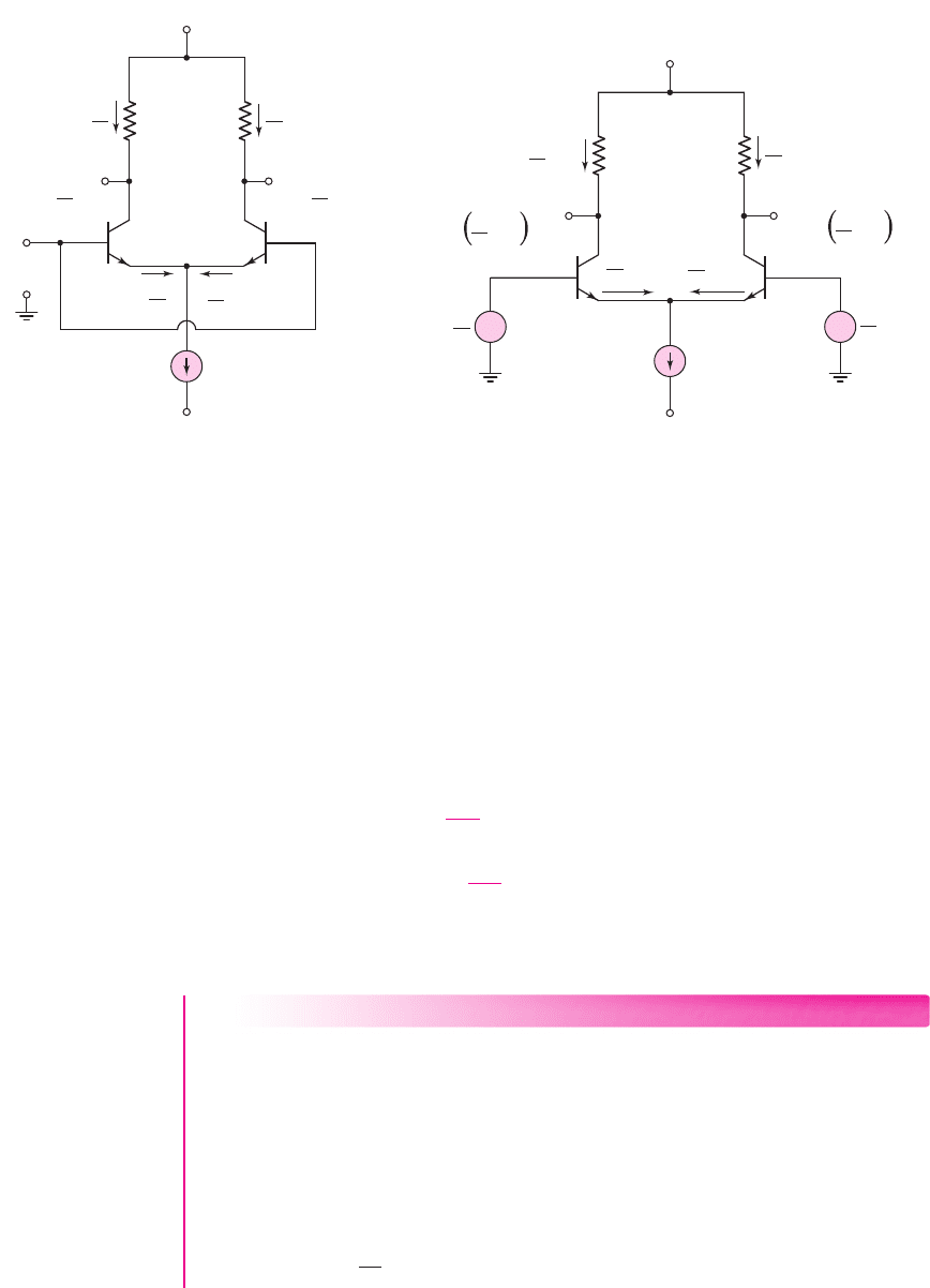
V
+
v
C1
v
C2
v
B1
v
BE1
v
B2
v
BE2
R
C
R
C
Q
1
Q
2
v
E
+
––
+
I
Q
V
–
+
–
+
–
i
C1
i
C2
i
E1
i
E2
Figure 11.2 Basic BJT differential-pair configuration
BJT Diff-Amp Operation—Qualitative Description
Figure 11.2 shows the basic BJT differential-pair configuration. Two identical
transistors, Q
1
and Q
2
, whose emitters are connected together, are biased by a constant-
current source I
Q
, which is connected to a negative supply voltage
V
−
. The collectors
of Q
1
and Q
2
are connected through resistors R
C
to a positive supply voltage
V
+
. By
design, transistors Q
1
and Q
2
are to remain biased in the forward-active region. We
assume that the two collector resistors R
C
are equal, and that v
B1
and v
B2
are ideal
sources, meaning that the output resistances of these sources are negligibly small.
11.2.1
Since both positive and negative bias voltages are used in the circuit, the need
for coupling capacitors and voltage divider biasing resistors at the inputs of Q
1
and
Q
2
has been eliminated. If the input signal voltages v
B1
and v
B2
in the circuit shown
in Figure 11.2 are both zero, Q
1
and Q
2
are still biased in the active region by the
current source I
Q
. The common-emitter voltage v
E
would be on the order of
−0.7V
.
This circuit, then, is referred to as a dc-coupled differential amplifier, so differences
in dc input voltages can be amplified. Although the diff-amp contains two transistors,
it is considered a single-stage amplifier. The analysis will show that it has character-
istics similar to those of the common-emitter amplifier.
First, we consider the circuit in which the two base terminals are connected
together and a common-mode voltage v
cm
is applied as shown in Figure 11.3(a). The
transistors are biased “on” by the constant-current source, and the voltage at the
common emitters is
v
E
= v
cm
− V
BE
(on)
. Since Q
1
and Q
2
are matched or identical,
current I
Q
splits evenly between the two transistors, and
i
E1
= i
E2
=
I
Q
2
(11.4)
If base currents are negligible, then
i
C1
∼
=
i
E1
and
i
C2
∼
=
i
E2
, and
v
C1
= V
+
−
I
Q
2
R
C
= v
C2
(11.5)
nea80644_ch11_753-850.qxd 6/19/09 4:37 AM Page 755 pmath DATA-DISK:Desktop Folder:18.6.09:MHDQ134-11:
756 Part 2 Analog Electronics
V
+
I
Q
R
C
R
C
+
–
Q
1
Q
2
v
cm
v
E
V
–
v
C2
=
I
Q
2
V
+
–
R
C
v
C1
=
I
Q
2
V
+
–
R
C
(a)
I
Q
2
I
Q
2
I
Q
2
I
Q
2
v
C1
= v
C2
=
v
BE2
v
BE1
R
C
R
C
V
+
v
d
2
v
d
2
– ΔI
I
Q
2
I
Q
2
+ ΔI
I
Q
2
[V
+
–
+ ΔI R
C
]
I
Q
2
[V
+
–
– ΔI R
C
]
++
––
V
–
I
Q
(b)
+
–
+
–
I
Q
2
+ ΔI
I
Q
2
– ΔI
Figure 11.3 Basic diff-amp with applied common-mode voltage and (b) basic diff-amp
with applied differential-mode voltage
We see from Equation (11.5) that, for an applied common-mode voltage, I
Q
splits
evenly between Q
1
and Q
2
and the difference between v
C1
and v
C2
is zero.
Now, if v
B1
increases by a few millivolts and v
B2
decreases by the same amount,
or
v
B1
= v
d
/2
and
v
B2
=−v
d
/2
, the voltages at the bases of Q
1
and Q
2
are no longer
equal. Since the emitters are common, this means that the B–E voltages on Q
1
and Q
2
are no longer equal. Since v
B1
increases and v
B2
decreases, then
v
BE1
>v
BE2
, which
means that i
C1
increases by
I above its quiescent value and i
C2
decreases by
I
below its quiescent value. This is shown in Figure 11.3(b). A potential difference
now exits between the two collector terminals. We can write
v
C2
−v
C1
=
V
+
−
I
CQ
2
−I
R
C
−
V
+
−
I
CQ
2
+I
R
C
= 2IR
C
(11.6)
A voltage difference is created between v
C2
and v
C1
when a differential-mode input
voltage is applied.
EXAMPLE 11.1
Objective: Determine the quiescent collector current and collector-emitter voltage
in a difference amplifier.
Consider the diff-amp in Figure 11.2, with circuit parameters:
V
+
= 10
V,
V
−
=−10 V
,
I
Q
= 1
mA, and
R
C
= 10 k
. The transistor parameters are:
β =∞
(neglect base currents),
V
A
=∞
, and
V
BE
(on) = 0.7
V. Determine i
C1
and v
CE1
for
common-mode voltages
v
B1
= v
B2
= v
CM
= 0, −5V
, and
+5
V.
Solution: We know that
i
C1
= i
C2
=
I
Q
2
= 0.5mA
nea80644_ch11_753-850.qxd 6/19/09 4:37 AM Page 756 pmath DATA-DISK:Desktop Folder:18.6.09:MHDQ134-11:
Chapter 11 Differential and Multistage Amplifiers 757
therefore,
v
C1
= v
C2
= V
+
−i
C1
R
C
= 10 −(0.5)(10) = 5V
From
v
CM
= 0,v
E
=−0.7V
and
v
CE1
= v
C1
−v
E
= 5 −(−0.7) = 5.7V
For
v
CM
=−5V
,
v
E
=−5.7V
and
v
CE1
= v
C1
−v
E
= 5 −(−5.7) = 10.7V
For
v
CM
=+5V,v
E
= 4.3
V and
v
CE1
= v
C1
−v
E
= 5 −4.3 = 0.7V
Comment: As the common-mode input voltage varies, the ideal constant current I
Q
still splits evenly between Q
1
and Q
2
, but the collector-emitter voltage varies, which
means that the Q-point changes. The variation in Q-point as a function of common-
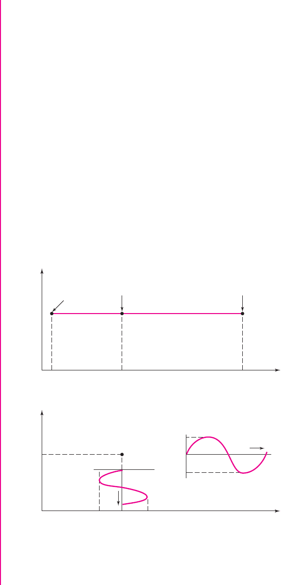
mode input voltage is shown in Figure 11.4(a). In this example, if v
CM
were to
increase about
+5
V, then Q
1
and Q
2
would be driven into saturation. This demon-
strates that there is a limited range of applied common-mode voltage over which Q
1
and Q
2
will remain biased in the forward-active mode.
Figure 11.4(b) shows the Q-point when
v
CM
= 0
and also shows the variation in
i
C1
and v
CE1
when an 18 mV sinusoidal differential voltage is applied.
i
C1
(mA)
v
CE1
(V)
v
CM
= 0
v
CM
= +5 V
v
CM
= –9.3 V
0.7 5.7 15.0
i
C1
(mA)
v
CE1
Time
Time
0.5
5.7 7.43
0.673
Q-point
0.327
3.97
(b)
(a)
Figure 11.4 (a) Variation of Q-point for transistor Q
1
in the BJT diff-amp as the common-
mode input voltage varies from
+5
to
−9.3V
; (b) change in collector current and
collector–emitter voltage versus time for transistor Q
1
in the BJT diff-amp when a
sinusoidal 18 mV differential voltage is applied
nea80644_ch11_753-850.qxd 6/19/09 4:37 AM Page 757 pmath DATA-DISK:Desktop Folder:18.6.09:MHDQ134-11: