Neamen D. Microelectronics: Circuit Analysis and Design
Подождите немного. Документ загружается.

768 Part 2 Analog Electronics
Trade-offs: If the common-mode gain requirement had been more stringent, a
different current source circuit might be required to provide a larger output resistance.
The effects of mismatched devices and elements are considered in the next section.
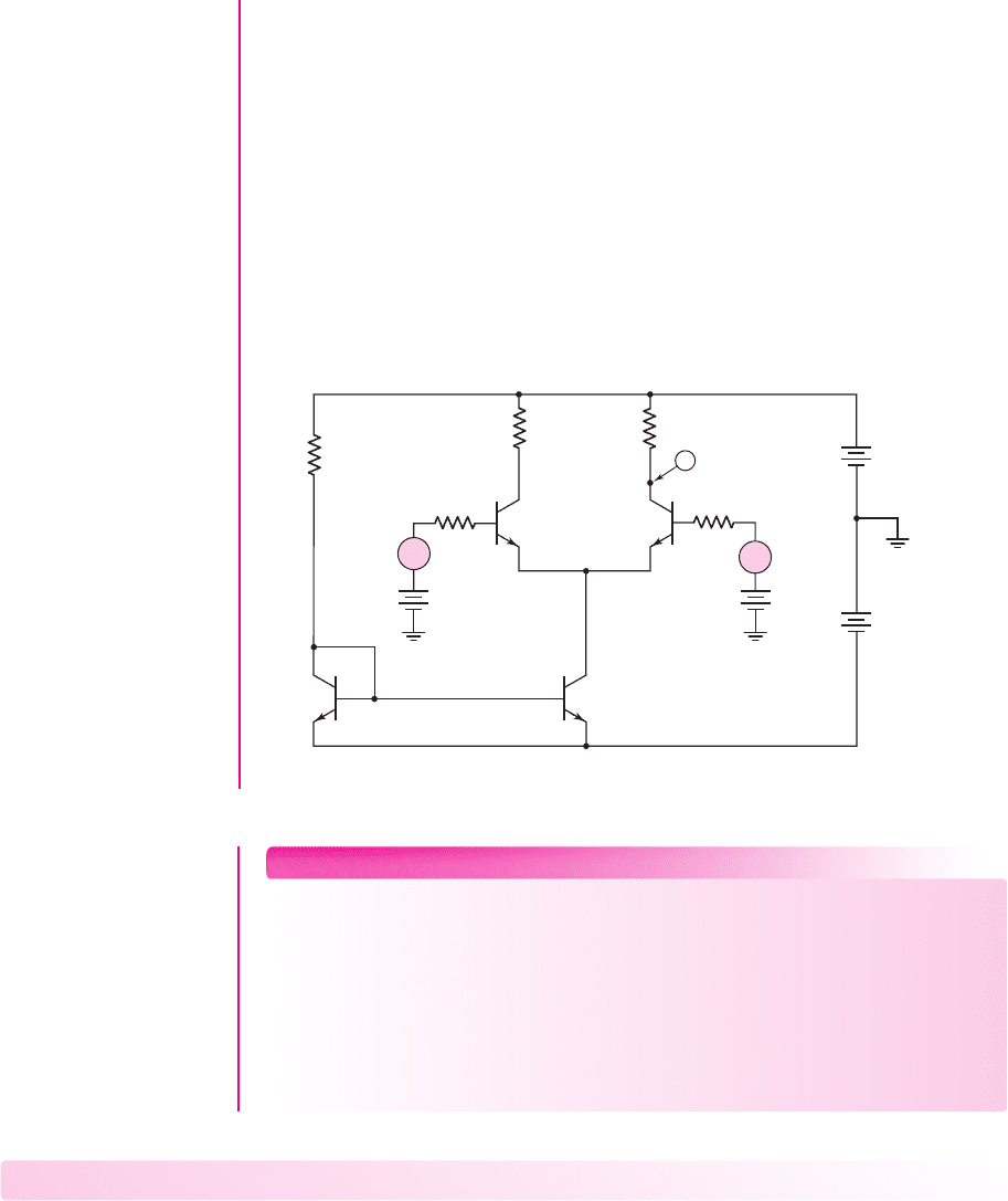
Computer Simulation Verification: Figure 11.11 shows the circuit used in the
computer simulation for this example. The bias current I
Q
supplied by the Q
3
current
source transistor is 0.568 mA. A 2.5 V common-mode input voltage is applied, a
500
source (probe) resistance is included, and an 8 mV differential-mode input
signal is applied. The differential output signal voltage measured at the collector of
Q
2
is 0.84 V, which is just slightly larger than the designed value. The current gains
of the standard 2N3904 transistors used in the computer simulation are larger than
the values of 100 used in the hand analysis and design. A common-mode signal volt-
age of 100 mV replaced the differential-mode signals. The common-mode output
signal is 7.11 mV, which is within the design specification.
38.6 kΩ
21.8 kΩ
0.5 kΩ
4 mV
2.5 V
21.8 kΩ
0.5 kΩ
V
2N39042N3904
2N3904 2N3904
–4 mV
2.5 V
10 V
0
0
0
10 V
+
–
+
–
+
–
+
–
R
3
Q
1
Q
4
Q
3
V
1
V
3
Q
2
R
B2
R
B1
R
2
R
1
V
5
V
2
V
4
V
6
+
–
∼
+
–
∼
Figure 11.11 Circuit used in the computer simulation of Design Example 11.4
EXERCISE PROBLEM
Ex 11.4: Consider the diff-amp configuration shown in Figure 11.7. Assume
Q
1
and
Q
2
are matched, let
V
A
=∞
, and neglect base currents. Let
I
Q
= 200 μ
A.
(a) Design the circuit such that the differential-mode gain at
v
C1
is
−150
, the
differential-mode gain at
v
C2
is
+100
, and the common-mode voltage is in the
range
−1.5 ≤ v
cm
≤ 1.5
V. (b) Using the results of part (a), what are the mini-
mum bias voltages
V
+
=−V
−
such that the input transistors always remain
biased in the forward-active region. (Ans. (a)
R
C1
= 78.0
k
,
R
C2
= 52.0
k
;
(b)
V
+
=−V
−
= 9.3
V)
Test Your Understanding
TYU 11.1 Find the differential- and common-mode components of the input signal
applied to a diff-amp for input voltages of (a)
v
1
= 2.100
V and
v
2
= 2.120
V; and
(b)
v
1
= 0.25 −0.002 sin ω t
V and
v
2
= 0.50 +0.002 sin ω t
V. (Ans. (a)
v
d
=
−0.02
V,
v
cm
= 2.110
V; (b)
v
d
=−0.25 − 0.004 sin ω t
V,
v
cm
= 0.375
V)
nea80644_ch11_753-850.qxd 6/19/09 4:37 AM Page 768 pmath DATA-DISK:Desktop Folder:18.6.09:MHDQ134-11:

Chapter 11 Differential and Multistage Amplifiers 769
TYU 11.2
Consider the diff-amp in Figure 11.2, with parameters
V
+
= 5
V,
V
−
=−5
V, and
I
Q
= 0.4
mA. (a) Redesign the circuit such that the common-
mode input voltage is in the range
−3 ≤ v
cm
≤ 3
V, while
Q
1
and
Q
2
remain biased
in the forward-active region. (b) Using the results of part (a), find the differential-
mode voltage gain
A
d
=
(
v
c2
−v
c1
)
/v
d
. (Ans. (a)
R
C
= 10
k
, (b)
A
d
= 76.9)
TYU 11.3 Assume the differential-mode gain of a diff-amp is
A
d
= 80
and the
common-mode gain is
A
cm
=−0.20
. Determine the output voltage for input
signals of: (a)
v
1
= 0.995 sin ωt
V and
v
2
= 1.005 sin ωt
V; and (b)
v
1
=
2 − 0.005 sin ω t
V and
v
2
= 2 +0.005 sin ω t
V. (Ans. (a)
v
o
=−1.0 sin ω t
V,
(b)
v
o
=−0.4 − 0.8 sin ω t
V)
Two-Sided Output
If we consider the two-sided output of an ideal op-amp and define the output voltage
as
V
o
= V
c2
− V
c1
, we can show that the differential-mode voltage gain is given by
A
d
=
β R
C
r
π
+ R
B
(11.36(a))
and the common-mode voltage gain is given by
A
cm
= 0
(11.36(b))
The result of
A
cm
= 0
for the two-sided output is a consequence of using matched
devices and elements in the diff-amp circuit. We will reconsider a two-sided output
and discuss the effects of mismatched elements.
Effect of R
C
Mismatch—Two-Sided Output
We assume that R
C1
and R
C2
are the resistors in the collectors of Q
1
and Q
2
. If the two
resistors are not matched, we assume that we can write
R
C1
= R
C
+R
C
and
R
C2
= R
C
−R
C
. For simplicity, let
R
B
= 0
.
From Figure 11.9, the output voltage for a two-sided output is given by
V
o
= V
c2
− V
c1
= (−g
m
V
π2
R
C2
) − (−g
m
V
π1
R
C1
)
(11.37)
We also see from the figure (with
R
B
= 0
) that
V
π1
= V
b1
− V
e
and
V
π2
= V
b2
− V
e
.
Using the expressions for V
e
(Equation (11.24), V
b1
(Equation (11.29(a)), and V
b2
(Equation (11.29(b)), we find the differential voltage gain as
A
d
= g
m
R
C
(11.38)
and the common-mode gain as
A
cm
= g
m
(2R
C
) ·
1
1 +
2(1 + β)R
o
r
π
(11.39)
In general,
2(1 + β)R
o
/r
π
1
, so that
A
cm
∼
=
g
m
(2R
C
) ·
r
π
2(1 + β)R
o
(11.40(a))
Noting that
g
m
r
π
= β and β/(1 + β)
∼
=
1
, we have the common-mode gain as
A
cm
∼
=
R
C
R
o
(11.40(b))
11.2.5
nea80644_ch11_753-850.qxd 6/19/09 4:37 AM Page 769 pmath DATA-DISK:Desktop Folder:18.6.09:MHDQ134-11:

770 Part 2 Analog Electronics
The common-mode rejection ratio is then
CMRR =
A
d
A
cm
=
g
m
R
o
(R
C
/R
C
)
(11.41)
Effect of g
m
Mismatch—Two-Sided Output
We can consider the effect of transistor mismatch by considering the effect of a mis-
match in the transconductance g
m
. We assume g
m1
and g
m2
are the transconductance
parameters of the two transistors in the diff-amp. We will assume that we can write
g
m1
= g
m
+g
m
and
g
m2
= g
m
−g
m
. Again, for simplicity, let
R
B
= 0
.
Again, from Figure 11.9, the output voltage for a two-sided output is
V
o
= V
c2
− V
c1
= (−g
m2
V
π2
R
C
) − (−g
m1
V
π1
R
C
)
(11.42)
Applying a differential input voltage, we find
V
π1
= V
d
/2 and V
π2
=−V
d
/2
. The
differential voltage gain is then
A
d
=
V
o
V
d
= g
m
R
C
(11.43)
Applying a common-mode input voltage, we have
V
π1
= V
π2
= V
cm
− V
e
. The out-
put voltage is again given by
V
o
= V
c2
− V
c1
= (−g
m2
V
π2
R
C
) − (−g
m1
V
π1
R
C
)
(11.44(a))
or
V
o
= (V
cm
− V
e
)R
C
(g
m1
− g
m2
)
(11.44(b))
Summing currents at the V
e
node in Figure 11.9, we have
V
π1
r
π1
+ g
m1
V
π1
+ g
m2
V
π2
+
V
π2
r
π2
=
V
e
R
o
(11.45)
In general, we have
g
m
1/r
π
. Then Equation (11.45) becomes
(V
cm
− V
e
)(g
m1
+ g
m2
) =
V
e
R
o
(11.46(a))
or
V
e
=
V
cm
(g
m1
+ g
m2
)
1
R
o
+ g
m1
+ g
m2
(11.46(b))
The output voltage is then
V
o
=
V
cm
−
V
cm
(g
m1
+ g
m2
)
(1/R
o
) + g
m1
+ g
m2
· R
C
(g
m1
− g
m2
)
(11.47)
Noting that
g
m1
+ g
m2
= 2g
m
and
g
m1
− g
m2
= 2(g
m
)
, the common-mode gain is
A
cm
=
R
C
(2g
m
)
1 + 2R
o
g
m
(11.48)
The common-mode rejection ratio now becomes
CMRR =
A
d
A
cm
=
1 + 2R
o
g
m
2(g
m
/g
m
)
(11.49)
nea80644_ch11_753-850.qxd 6/19/09 4:37 AM Page 770 pmath DATA-DISK:Desktop Folder:18.6.09:MHDQ134-11:
Chapter 11 Differential and Multistage Amplifiers 771
Differential- and Common-Mode
Gains—Further Observations
For greater insight into the mechanism that causes differential- and common-mode
gains, we reconsider the diff-amp as pure differential- and common-mode signals are
applied.
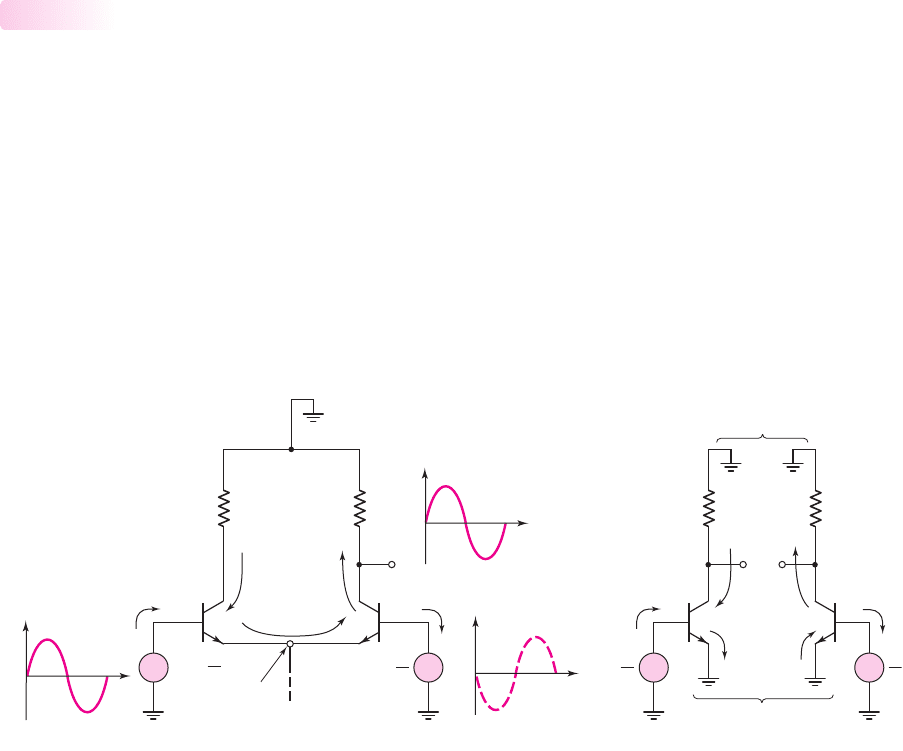
Figure 11.12(a) shows the ac equivalent circuit of the diff-amp with two sinu-
soidal input signals. The two input voltages are 180 degrees out of phase, so a pure
differential-mode signal is being applied to the diff-amp. We see that
v
b1
+v
b2
= 0
.
From Equation (11.24), we find
v
e
= 0
, so the common emitters of Q
1
and Q
2
remain
at signal ground. In essence, the circuit behaves like a balanced seesaw. As the base
voltage of Q
1
goes into its positive-half cycle, the base voltage of Q
2
is in its nega-
tive half-cycle. Then, as the base voltage of Q
1
goes into its negative half-cycle, the
base voltage of Q
2
is in its positive half-cycle. The signal current directions shown in
the figure are valid for v
b1
in its positive half-cycle.
11.2.6
R
C
R
C
v
o
Q
1
Q
2
Signal ground
Signal
ground
v
b1
v
b2
v
o
t
v
b1
=
v
d
2
v
e
v
d
2
v
b2
= –
t
+
–
+
–
R
C
R
C
Signal ground
Signal ground
v
c1
v
c2
v
d
2
v
d
2
+
–
–
+
(a) (b)
Figure 11.12 (a) Equivalent ac circuit, diff-amp with applied sinusoidal differential-mode
input signal, and resulting signal current directions and (b) differential-mode half-circuits
Since v
e
is always at ground potential, we can treat each half of the diff-amp
as a common-emitter circuit. Figure 11.12(b) shows the differential half-circuits,
clearly depicting the common-emitter configuration. The differential-mode charac-
teristics of the diff-amp can be determined by analyzing the half-circuit. In evaluat-
ing the small-signal hybrid-
π
parameters, we must keep in mind that the half-circuit
is biased at I
Q
/2.
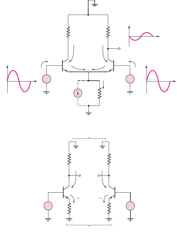
Figure 11.13(a) shows the ac equivalent circuit of the diff-amp with a pure
common-mode sinusoidal input signal. In this case, the two input voltages are in
phase. The current source is represented as an ideal source I
Q
in parallel with its out-
put resistance R
o
. Current i
q
is the time-varying component of the source current. As
the two input signals increase, voltage v
e
increases and current i
q
increases. Since this
current splits evenly between Q
1
and Q
2
, each collector current also increases. The
output voltage v
o
then decreases below its quiescent value.
As the two input voltages go through the negative half-cycle, all signal currents
shown in the figure reverse direction, and v
o
increases above its quiescent value.
nea80644_ch11_753-850.qxd 6/19/09 4:37 AM Page 771 pmath DATA-DISK:Desktop Folder:18.6.09:MHDQ134-11:
772 Part 2 Analog Electronics
Consequently, a common-mode sinusoidal input signal produces a sinusoidal output
voltage, which means that the diff-amp has a nonzero common-mode voltage gain. If the
value of R
o
increases, the magnitude of i
q
decreases for a given common-mode input sig-
nal, producing a smaller output voltage and hence a smaller common-mode gain.
With an applied common-mode voltage, the circuit shown in Figure 11.13(a) is
perfectly symmetrical. The circuit can therefore be split into the identical common-
mode half-circuits shown in Figure 11.13(b). The common-mode characteristics of the
diff-amp can then be determined by analyzing the half-circuit, which is a common-
emitter configuration with an emitter resistor. Each half-circuit is biased at I
Q
/2.
The following examples further illustrate the effect of a nonzero common-mode
gain on circuit performance.
(a)
(b)
Signal ground
Signal ground
R
C
R
C
v
c1
v
cm
v
cm
v
c2
i
q
2
i
q
2
2R
o
2R
o
+
–
+
–
i
q
R
C
R
C
v
o
Q
1
Q
2
Signal ground
Signal ground
v
b1
t
v
b2
v
o
t
v
b1
= v
cm
v
b2
= v
cm
v
e
R
o
I
Q
+
–
+
–
+
–
Figure 11.13 (a) Equivalent ac circuit of diff-amp with common-mode input signal, and
resulting signal current directions and (b) common-mode half-circuits
nea80644_ch11_753-850.qxd 6/19/09 4:37 AM Page 772 pmath DATA-DISK:Desktop Folder:18.6.09:MHDQ134-11:

Chapter 11 Differential and Multistage Amplifiers 773
EXAMPLE 11.5
Objective: Determine the output of a diff-amp when both differential- and common-
mode signals are applied.
Consider the circuit shown in Figure 11.2. Use the transistor and circuit para-
meters described in Example 11.3. Assume that four sets of inputs are applied, as
described in the following table, which also includes the differential- and common-
mode voltages.
Solution: The output voltage is given by Equation (11.31), as follows:
v
o
= A
d
v
d
+ A
cm
v
cm
From Example 11.3, the differential- and common-mode gains are
A
d
= 92.3
and
A
cm
=−0.237
. The output voltages for the four sets of inputs are:
Comment: In cases 1 and 2, the common-mode input is zero, and the output is
directly proportional to the differential input signal. Comparing cases 1 and 3 and
cases 2 and 4, we see that the output voltages are not equal, even though the differ-
ential input signals are the same. This shows that the common-mode signal affects
the output. Also, even though the differential signal is doubled, in cases 4 and 3, the
ratio of the output signals is not 2.0. If a common-mode signal is present, the output
is not exactly linear with respect to the differential input signal.
For Case 5, the differential-input voltage is zero, but the output voltage is not
zero, since a common-mode input voltage exists and
|
A
cm
|
= 0
.
Output signal (mV)
Case 1
v
o
= 1.846 sin ωt
Case 2
v
o
= 3.692 sin ωt
Case 3
v
o
= 1.799 sin ωt
Case 4
v
o
= 3.645 sin ωt
Case 5
v
o
=−0.0474 sin ωt
Differential- and
common-mode
Input signal (μV) input signals (μV)
Case 1
v
1
= 10 sin ωt v
d
= 20 sin ωt
v
2
=−10 sin ωt v
cm
= 0
Case 2
v
1
= 20 sin ωt v
d
= 40 sin ωt
v
2
=−20 sin ωt v
cm
= 0
Case 3
v
1
= 210 sin ωt v
d
= 20 sin ωt
v
2
= 190 sin ωt v
cm
= 200 sin ωt
Case 4
v
1
= 220 sin ωt v
d
= 40 sin ωt
v
2
= 180 sin ωt v
cm
= 200 sin ωt
Case 5
v
1
= 200 sin ωt v
d
= 0
v
2
= 200 sin ωt v
cm
= 200 sin ωt
nea80644_ch11_753-850.qxd 6/19/09 4:37 AM Page 773 pmath DATA-DISK:Desktop Folder:18.6.09:MHDQ134-11:

774 Part 2 Analog Electronics
EXERCISE PROBLEM
Ex 11.5: Assume a diff-amp has a differential-mode gain of
A
d
= 150
and a
common-mode rejection ratio of CMMR
dB
= 50
dB. Assume
A
cm
is positive.
Determine the output voltage if the input voltages are (a)
v
1
=−10 μ
V,
v
2
=+10 μ
V and (b)
v
1
= 190 μ
V,
v
2
= 210 μ
V. (Ans. (a)
v
o
=−3.0
mV,
(b)
v
o
=−2.905
mV)
As mentioned previously, the common-mode gain is a function of the output
resistance of the current source. If the required common-mode gain needs to be re-
duced, then the current source output resistance must be increased, which may
require the design of a more sophisticated current source.
Problem-Solving Technique: Diff-Amps with Resistive Loads
1. To determine the differential-mode voltage gain, apply a pure differential-
mode input voltage and use the differential-mode half-circuit in the analysis.
2. To determine the common-mode voltage gain, apply a pure common-mode
input voltage and use the common-mode half-circuit in the analysis.
Differential- and Common-Mode Input Impedances
The input impedance, or resistance, of an amplifier is as important a property as the
voltage gain. The input resistance determines the loading effect of the circuit on
the signal source. We will look at two input resistances for the difference amplifier:
the differential-mode input resistance, which is the resistance seen by a differential-
mode signal source; and the common-mode input resistance, which is the resis-
tance seen by a common-mode input signal source.
Differential-Mode Input Resistance
The differential-mode input resistance is the effective resistance between the two
input base terminals when a differential-mode signal is applied. A diff-amp with a
pure differential input signal is shown in Figure 11.14. The applicable differential-
mode half-circuits were shown in Figure 11.12(b). For this circuit, we have
v
d
/2
i
b
= r
π
(11.50)
The differential-mode input resistance is therefore
R
id
=
v
d
i
b
= 2r
π
(11.51)
Another common diff-amp configuration uses emitter resistors, as shown in
Figure 11.15. With a pure applied differential-mode voltage, similar differential-mode
half-circuits are applicable to this configuration. We can then use the resistance re-
flection rule to find the differential-mode input resistance. We have
v
d
/2
i
b
= r
π
+(1 +β)R
E
(11.52)
11.2.7
nea80644_ch11_753-850.qxd 6/19/09 4:37 AM Page 774 pmath DATA-DISK:Desktop Folder:18.6.09:MHDQ134-11:
Therefore,
R
id
=
v
d
i
b
= 2[r
π
+(1 +β)R
E
]
(11.53)
Equation (11.53) implies that the differential-mode input resistance increases sig-
nificantly when emitter resistors are included. We will see that the differential-mode
gain decreases when emitter resistors are included in the same way that the voltage
gain of a common-emitter amplifier decreases when an emitter resistor is included in
the design. However, a larger differential-mode voltage (greater than 18 mV) may be
applied to the diff-amp in Figure 11.15 and the amplifier remains linear.
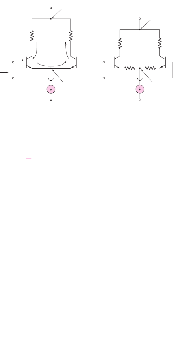
Common-Mode Input Resistance
Figure 11.16(a) shows a diff-amp with an applied common-mode voltage. The small-
signal output resistance R
o
of the constant-current source is also shown. The equiva-
lent common-mode half-circuits were given in Figure 11.13(b). Since the half-cir-
cuits are in parallel, we can write
2R
icm
= r
π
+(1 +β)(2R
o
)
∼
=
(1 + β)(2R
o
)
(11.54)
Equation (11.54) is a first approximation for determining the common-mode input
resistance.
Normally, R
o
is large, and R
icm
is typically in the megohm range. Therefore, the
transistor output resistance r
o
and the base–collector resistance
r
μ
may need to be
included in the calculation. Figure 11.16(b) shows the more complete equivalent
half-circuit model. For this model, we have
2R
icm
= r
μ
[(1 + β)(2R
o
)]
[(1 + β)r
o
]
(11.55(a))
Therefore,
R
icm
=
r
μ
2
[(1 + β)(R
o
)]
(1 + β)
r
o
2
(11.55(b))
Chapter 11 Differential and Multistage Amplifiers 775
+
–
v
d
I
Q
i
b
Signal ground
Signal
ground
R
C
R
C
V
+
V
–
R
id
Q
1
Q
2
Figure 11.14 BJT differential amplifier
with differential-mode input signal,
showing differential input resistance
+
–
v
d
Signal ground
Signal
ground
V
+
V
–
Q
1
Q
2
I
Q
R
E
R
C
R
C
R
E
Figure 11.15 BJT differential
amplifier with emitter resistors
nea80644_ch11_753-850.qxd 6/19/09 4:37 AM Page 775 pmath DATA-DISK:Desktop Folder:18.6.09:MHDQ134-11:
776 Part 2 Analog Electronics
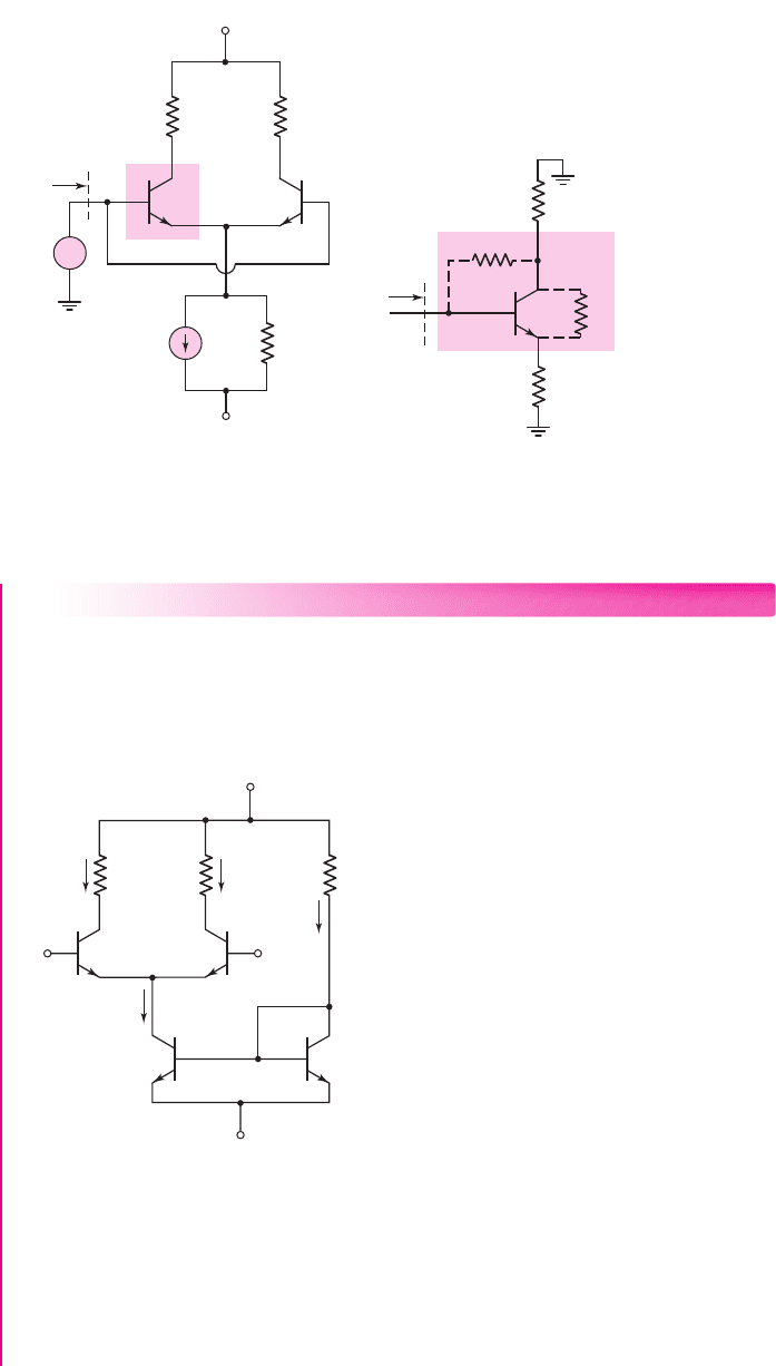
EXAMPLE 11.6
Objective: Determine the differential- and common-mode input resistances of a dif-
ferential amplifier.
Consider the circuit in Figure 11.17, with transistor parameters
β = 100
,
V
BE
(on) = 0.7
V, and
V
A
= 100
V. Determine
R
id
and
R
icm
.
+5 V
R
C
=
8 kΩ
R
C
=
8 kΩ
R
1
=
18.6 kΩ
I
1
I
2
I
REF
v
1
Q
1
v
2
Q
2
I
Q
Q
4
Q
3
–5 V
Figure 11.17 BJT differential amplifier for Example 11.6
(a) (b)
Signal
ground
Signal ground
R
C
2R
icm
2R
o
r
m
r
o
R
icm
R
C
R
C
v
cm
R
o
V
+
V
–
I
Q
+
–
Figure 11.16 (a) BJT differential amplifier with common-mode input signal, including finite
current source resistance and (b) equivalent common-mode half-circuit
Solution:
From the circuit, we find
I
REF
= 0.5mA
∼
=
I
Q
and
I
1
= I
2
∼
=
I
Q
/2 = 0.25 mA
nea80644_ch11_753-850.qxd 6/19/09 4:37 AM Page 776 pmath DATA-DISK:Desktop Folder:18.6.09:MHDQ134-11:

Chapter 11 Differential and Multistage Amplifiers 777
The small-signal parameters for Q
1
and Q
2
are then
r
π
=
βV
T
I
CQ
=
(100)(0.026)
0.25
= 10.4k
and
r
o
=
V
A
I
CQ
=
100
0.25
= 400 k
and the output resistance of Q
4
is
R
o
=
V
A
I
Q
=
100
0.5
= 200 k
From Equation (11.51), the differential-mode input resistance is
R
id
= 2r
π
= 2(10.4) = 20.8k
From Equation (11.55(b)), neglecting the effect of
r
μ
, the common-mode input
resistance is
R
icm
= (1 +β)
(R
o
)
r
o
2
= (101)
200
400
2
k → 10.1M
Comment: If a differential-mode input voltage with a peak value of 15 mV is
applied, the source must be capable of supplying a current of
15 × 10
−3
/20.8 ×
10
+3
= 0.72 μA
without any severe loading effect. However, the input current from
a 15 mV common-mode signal would only be approximately 1.5 nA.
EXERCISE PROBLEM
Ex 11.6: Consider the diff-amp shown in Figure 11.15. Assume the current
source has a value of
I
Q
= 0.5
mA, the transistor current gains are
β = 100
, and
the emitter resistors are
R
E
= 500
. Find the differential input resistance.
(Ans.
R
id
= 122 k
)
Differential-Mode Voltage Gain with Emitter Degeneration
We may determine the differential-mode voltage gain of the circuit shown in Fig-
ure 11.15. Figure 11.18 shows the differential-mode half circuits. For a one-sided
output and for matched elements, we have
V
o
= V
c2
=−g
m
V
π2
R
C
(11.56)
Q
1
Q
2
R
C
R
C
V
p 2
R
E
R
E
V
o
V
d
V
d
2
2
+
–
–
+
+
–
Figure 11.18 Differential half-circuits with emitter degeneration
nea80644_ch11_753-850.qxd 6/19/09 4:37 AM Page 777 pmath DATA-DISK:Desktop Folder:18.6.09:MHDQ134-11: