Neamen D. Microelectronics: Circuit Analysis and Design
Подождите немного. Документ загружается.


778 Part 2 Analog Electronics
Writing a KVL equation around the B–E loop, we have
V
d
2
+ V
π2
+ g
m
V
π2
R
E
= 0
(11.57)
which yields
V
π2
=
−(V
d
/2)
1 + g
m
R
E
(11.58)
Substituting Equation (11.58) into (11.56), we find the differential-mode voltage
gain as
A
d
=
V
o
V
d
=
g
m
R
C
2(1 + g
m
R
E
)
(11.59)
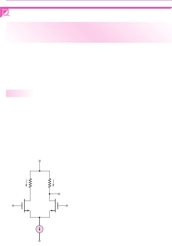
EXAMPLE 11.7
Objective: Determine the one-sided differential-mode voltage gain of the circuit
shown in Figure 11.15.
Assume
I
Q
= 0.5
mA,
β = 100
, and
R
C
= 10
k
. Find the differential-mode
voltage gain for (a)
R
E
= 0
and (b)
R
E
= 500
.
Solution: The small-signal transconductance is found to be
g
m
= 9.62
mA/V. We
find the differential-mode voltage gain to be (a) for
R
E
= 0
:
A
d
=
g
m
R
C
2
=
(9.62)(10)
2
= 48.1
and (b) for
R
E
= 500
:
A
d
=
g
m
R
C
2(1 + g
m
R
E
)
=
(9.62)(10)
2[1 + (9.62)(0.5)]
= 8.28
Comment: As with any design problem, there are trade-offs. Including an emitter re-
sistor R
E
decreases the voltage gain but increases the input differential-mode resistance.
EXERCISE PROBLEM
Ex 11.7: Consider the diff-amp described in Example 11.7. Assume the same
parameters except the value of R
E
. Determine the value of R
E
that results in a
differential-mode voltage gain of
A
d
= 10
. What is the corresponding value of
differential-input resistance? (Ans.
R
E
= 0.396 k
,
R
id
= 100.8k
)
Test Your Understanding
TYU 11.4 Consider the effect of a mismatch in collector resistors. Assume that
g
m
= 3.86
mA/V
2
,
R
o
= 100 k
, and a nominal collector resistor of
R
C
= 10 k
.
Determine the minimum mismatch in the collector resistor
R
C
such that the common-
mode rejection ratio is 75 dB. (Ans.
R
C
= 0.686 k
)
TYU 11.5 Consider the effect of a mismatch in the transconductance of the transistors.
Assume
R
o
= 100 k
and the nominal transconductance is
g
m
= 3.86
mA/V. Deter-
mine the minimum mismatch in the transconductance
g
m
such that the common-
mode rejection ratio is 90 dB. (Ans.
g
m
= 0.0472
mA/V or
g
m
/g
m
→ 1.22%
)
nea80644_ch11_753-850.qxd 6/19/09 4:37 AM Page 778 pmath DATA-DISK:Desktop Folder:18.6.09:MHDQ134-11:
Chapter 11 Differential and Multistage Amplifiers 779
TYU 11.6 The parameters of the diff-amp shown in Figure 11.2 are
V
+
= 5
V,
V
−
=−5
V,
I
Q
= 0.4
mA, and
R
C
= 10
k
. The output resistance of the constant-
current source is
R
o
= 100
k
. The transistor parameters are
β = 150
,
V
BE
(
on
)
= 0.7
V, and
V
A
=∞
. (a) Determine the dc input base currents. (b) Deter-
mine the differential signal input currents if a differential-mode input voltage
v
d
= 10 sin ω t
mV is applied. (c) If a common-mode input voltage
v
cm
= 3 sin ωt
V
is applied, determine the common-mode signal input base currents. (Ans. (a)
I
B1
=
I
B2
= 1.32 μ
A, (b)
I
b
= 0.256 sin ωt μ
A, (c)
I
b
= 0.0993 sin ωt μ
A)
11.3 BASIC FET DIFFERENTIAL PAIR
Objective: • Describe the characteristics of and analyze the basic
FET differential amplifier.
In this section, we will evaluate the basic FET differential amplifier, concentrating on
the MOSFET diff-amp. As we did for the bipolar diff-amp, we will develop the dc
transfer characteristics, and determine the differential- and common-mode gains.
Differential amplifiers using JFETs are also available. Since the analysis is almost
identical to that for the MOSFET diff-amp, we will only briefly consider the JFET dif-
ferential pair. A few of the problems at the end of this chapter are based on these circuits.
DC Transfer Characteristics
Figure 11.19 shows the basic MOSFET differential pair, with matched transistors M
1
and M
2
biased with a constant current I
Q
. We assume that M
1
and M
2
are always
biased in the saturation region.
Like the basic bipolar configuration, the basic MOSFET diff-amp uses both
positive and negative bias voltages, thereby eliminating the need for coupling capacitors
and voltage divider biasing resistors at the gate terminals. Even with
v
G1
= v
G2
= 0
,
the transistors M
1
and M
2
can be biased in the saturation region by the current source I
Q
.
This circuit, then, is also a dc-coupled diff-amp.
11.3.1
V
+
V
–
R
D
R
D
i
D1
i
D2
v
O
M
1
M
2
v
G2
v
G1
++
––
++
––
v
GS2
v
GS1
I
Q
Figure 11.19 Basic MOSFET differential pair configuration
nea80644_ch11_753-850.qxd 6/19/09 4:37 AM Page 779 pmath DATA-DISK:Desktop Folder:18.6.09:MHDQ134-11:
780 Part 2 Analog Electronics
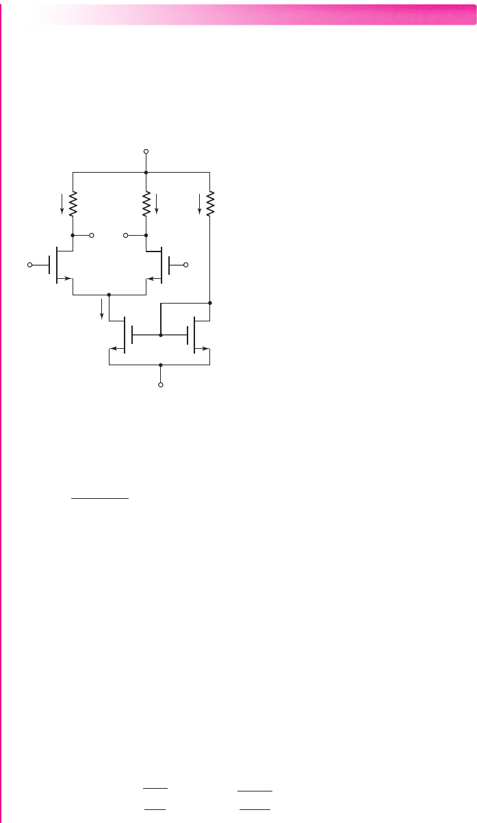
EXAMPLE 11.8
Objective: Calculate the dc characteristics of a MOSFET diff-amp.
Consider the differential amplifier shown in Figure 11.20. The transistor parameters
are:
K
n1
= K
n2
= 0.1
mA/V
2
,
K
n3
= K
n4
= 0.3
mA/V
2
, and for all transistors,
λ = 0
and
V
TN
= 1
V. Determine the maximum range of common-mode input voltage.
V
–
= –10 V
V
+
= 10 V
R
D
=
16 kΩ
R
D
=
16 kΩ
R
1
=
30 kΩ
I
D1
I
D2
I
1
v
O1
v
O2
v
1
v
2
M
1
M
4
M
3
M
2
I
Q
v
GS4
+
–
Figure 11.20 MOSFET differential amplifier for Example 11.8
Solution:
The reference current can be determined from
I
1
=
20 − V
GS4
R
1
and from
I
1
= K
n3
(V
GS4
− V
TN
)
2
Combining these two equations and substituting the parameter values, we obtain
9V
2
GS4
−17V
GS4
−11 = 0
which yields
V
GS4
= 2.40 V and I
1
= 0.587 mA
Since M
3
and M
4
are identical, we also find
I
Q
= 0.587 mA
The quiescent drain currents in M
l
and M
2
are
I
D1
= I
D2
= I
Q
/2
∼
=
0.293 mA
The gate-to-source voltages are then
V
GS1
= V
GS2
=
I
D1
K
n1
+ V
TN
=
0.293
0.1
+1 = 2.71 V
nea80644_ch11_753-850.qxd 6/19/09 4:37 AM Page 780 pmath DATA-DISK:Desktop Folder:18.6.09:MHDQ134-11:

Chapter 11 Differential and Multistage Amplifiers 781
The quiescent values of
v
O1
and
v
O2
are
v
O1
= v
O2
= 10 − I
D1
R
D
= 10 −(0.293)(16) = 5.31 V
The maximum common-mode input voltage is the value when M
1
and M
2
reach
the transition point, or
V
DS1
= V
DS2
= V
DS1
(sat) = V
GS1
− V
TN
= 2.71 −1 = 1.71 V
Therefore,
v
CM
(max) = v
O1
− V
DS1
(sat) + V
GS1
= 5.31 −1.71 +2.71
or
v
CM
(max) = 6.31 V
The minimum common-mode input voltage is the value when M
4
reaches the
transition point, or
V
DS4
= V
DS4
(sat) = V
GS4
− V
TN
= 2.4 −1 = 1.4V
Therefore,
v
CM
(min) = V
GS1
+ V
DS4
(sat) − 10 = 2.71 +1.4 −10
or
v
CM
(min) =−5.89 V
Comment: For this circuit the maximum range for the common-mode input voltage
is
−5.89 ≤ v
CM
≤ 6.31 V
.
EXERCISE PROBLEM
*Ex 11.8: For the differential amplifier in Figure 11.20, the parameters are:
V
+
= 5
V,
V
−
=−5
V,
R
1
= 80 k
, and
R
D
= 40
k
. The transistor parameters
are
λ = 0
and
V
TN
= 0.8
V for all transistors, and
K
n3
= K
n4
= 100 μA/V
2
and
K
n1
= K
n2
= 50 μA/V
2
. Determine the range of the common-mode input volt-
age. (Ans.
−2.18 ≤ v
cm
≤ 3.76 V
)
The dc transfer characteristics of the MOSFET differential pair can be deter-
mined from the circuit in Figure 11.19. Neglecting the output resistances of M
1
and
M
2
, and assuming the two transistors are matched, we can write
i
D1
= K
n
(v
GS1
− V
TN
)
2
(11.60(a))
and
i
D2
= K
n
(v
GS2
− V
TN
)
2
(11.60(b))
Taking the square roots of Equations (11.60(a)) and (11.60(b)), and subtracting the
two equations, we obtain
i
D1
−
i
D2
=
K
n
(v
GS1
−v
GS2
) =
K
n
· v
d
(11.61)
where
v
d
= v
G1
−v
G2
= v
GS1
−v
GS2
is the differential-mode input voltage. If
v
d
> 0
, then
v
G1
>v
G2
and
v
GS1
>v
GS2
, which implies that
i
D1
> i
D2
. Since
i
D1
+i
D2
= I
Q
(11.62)
nea80644_ch11_753-850.qxd 6/19/09 4:37 AM Page 781 pmath DATA-DISK:Desktop Folder:18.6.09:MHDQ134-11:
782 Part 2 Analog Electronics
then Equation (11.61) becomes
i
D1
−
I
Q
−i
D1
2
=
K
n
· v
d
2
= K
n
v
2
d
(11.63)
when both sides of the equation are squared. After the terms are rearranged, Equa-
tion (11.63) becomes
i
D1
(I
Q
−i
D1
) =
1
2
I
Q
− K
n
v
2
d
(11.64)
If we square both sides of this equation, we develop the quadratic equation
i
2
D1
− I
Q
i
D1
+
1
4
I
Q
− K
n
v
2
d
2
= 0
(11.65)
Applying the quadratic formula, rearranging terms, and noting that
i
D1
> I
Q
/2
and
v
d
> 0
, we obtain
i
D1
=
I
Q
2
+
K
n
I
Q
2
· v
d
1 −
K
n
2I
Q
v
2
d
(11.66)
Using Equation (11.62), we find that
i
D2
=
I
Q
2
−
K
n
I
Q
2
· v
d
1 −
K
n
2I
Q
v
2
d
(11.67)
The normalized drain currents are
i
D1
I
Q
=
1
2
+
K
n
2I
Q
· v
d
1 −
K
n
2I
Q
v
2
d
(11.68)
and
i
D2
I
Q
=
1
2
−
K
n
2I
Q
· v
d
1 −
K
n
2I
Q
v
2
d
(11.69)
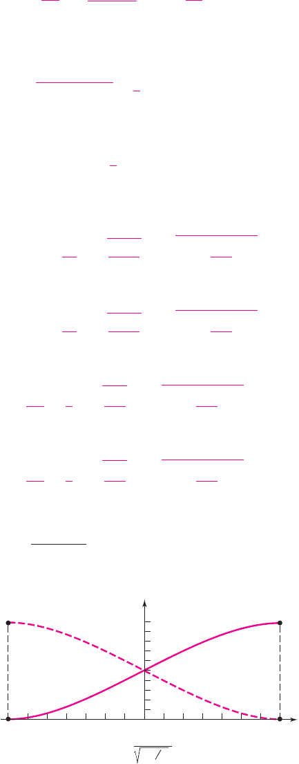
These equations describe the dc transfer characteristics for this circuit. They are
plotted in Figure 11.21 as a function of a normalized differential input voltage
v
d
/
(2I
Q
/K
n
)
.
–0.6 –0.4 –0.2 0 0.2 0.4 0.6
0.5
1.0
i
D1
/I
Q
i
D2
/I
Q
v
d
′
=
v
d
K
n
2I
Q
Figure 11.21 Normalized dc transfer characteristics,
MOSFET differential amplifier
nea80644_ch11_753-850.qxd 6/19/09 4:37 AM Page 782 pmath DATA-DISK:Desktop Folder:18.6.09:MHDQ134-11:
Chapter 11 Differential and Multistage Amplifiers 783
We can see from Equations (11.68) and (11.69) that, at a specific differential
input voltage, bias current I
Q
is switched entirely to one transistor or the other. This
occurs when
|
v
d
|
max
=
I
Q
K
n
(11.70)
The forward transconductance is defined as the slope of the i
D1
versus
v
d
transfer
characteristic evaluated at
v
d
= 0
, or
g
f
(max) =
di
D1
dv
d
v
d
=0
(11.71)
Using Equation (11.66), we find that
g
f
(max) =
K
n
I
Q
2
=
g
m
2
(11.72)
where g
m
is the transconductance of each transistor. The slope of the i
D2
characteris-
tic curve at
v
d
= 0
is the same, except it is negative.
We can perform an analysis similar to that in Example 11.2 to determine the
maximum differential-mode input signal that can be applied and still maintain
linearity. If we let
I
Q
= 1
mA and
K
n
= 1
mA/V
2
, then for differential input voltages
less than 0.34 V, the difference between the linear approximation and the actual curve
is less than 1 percent. The maximum differential input signal for the MOSFET diff-
amp is much larger than for the bipolar diff-amp. The principal reason is that the gain
of the MOSFET diff-amp, as we will see, is much smaller than the gain of the bipo-
lar diff-amp.
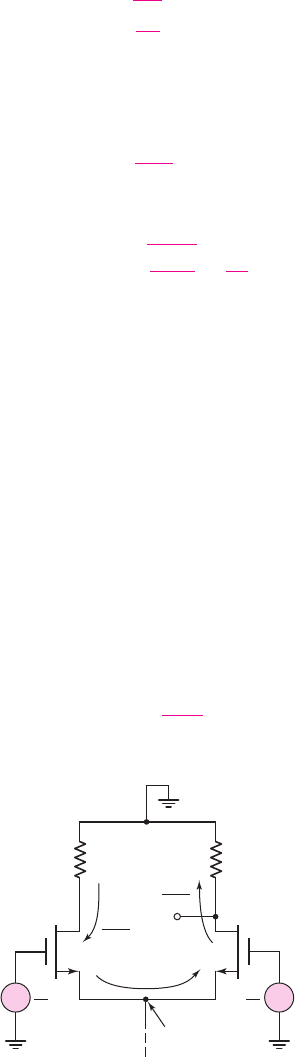
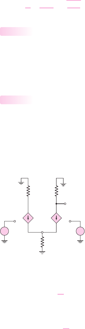
Figure 11.22 is the ac equivalent circuit of the diff-amp configuration, showing
only the differential voltage and signal currents as a function of the transistor
transconductance g
m
. We assume that the output resistance looking into the current
source is infinite. Using this equivalent circuit, we find the one-sided output voltage
at v
o2
, as follows:
v
o2
≡ v
o
=+
g
m
v
d
2
R
D
(11.73)
R
D
R
D
g
m
v
d
2
v
o2
M
1
M
2
+
–
–
+
g
m
v
d
2
v
d
2
v
d
2
Signal
ground
Figure 11.22 AC equivalent circuit,
MOSFET differential amplifier
nea80644_ch11_753-850.qxd 6/19/09 4:37 AM Page 783 pmath DATA-DISK:Desktop Folder:18.6.09:MHDQ134-11:
784 Part 2 Analog Electronics
The differential voltage gain is then
A
d
=
v
o
v
d
=
g
m
R
D
2
=
K
n
I
Q
2
· R
D
(11.74)
Differential- and Common-Mode Input Impedances
At low frequencies, the input impedance of a MOSFET is essentially infinite, which
means that both the differential- and common-mode input resistances of a MOSFET
diff-amp are infinite. Also, we know that the differential input resistance of a bipolar
pair can be in the low kilohm range. A design trade-off, then, would be to use a
MOSFET diff-amp with infinite input resistance, and sacrifice the differential-mode
voltage gain.
Small-Signal Equivalent Circuit Analysis
We can determine the basic relationships for the differential-mode gain, common-
mode gain, and common-mode rejection ratio from an analysis of the small-signal
equivalent circuit.
Figure 11.23 shows the small-signal equivalent circuit of the MOSFET differ-
ential pair configuration. We assume the transistors are matched, with
λ = 0
for each
transistor, and that the constant-current source is represented by a finite output
resistance R
o
. All voltages are represented by their phasor components. The two tran-
sistors are biased at the same quiescent current, and
g
m1
= g
m2
≡ g
m
.
11.3.3
11.3.2
R
D
R
D
V
o
= V
d2
g
m
V
gs2
g
m
V
gs1
V
s
+
+
V
gs1
V
gs2
–
–
V
1
V
2
R
o
+
–
+
–
Figure 11.23 Small-signal equivalent circuit, MOSFET differential amplifier
Writing a KCL equation at node V
s
, we have
g
m
V
gs1
+ g
m
V
gs2
=
V
s
R
o
(11.75)
From the circuit, we see that
V
gs1
= V
1
− V
s
and
V
gs2
= V
2
− V
s
. Equation (11.75)
then becomes
g
m
(V
1
+ V
2
−2V
s
) =
V
s
R
o
(11.76)
nea80644_ch11_753-850.qxd 6/19/09 4:37 AM Page 784 pmath DATA-DISK:Desktop Folder:18.6.09:MHDQ134-11:

Chapter 11 Differential and Multistage Amplifiers 785
Solving for V
s
we obtain
V
s
=
V
1
+ V
2
2 +
1
g
m
R
o
(11.77)
For a one-sided output at the drain of M
2
, we have
V
o
= V
d2
=−(g
m
V
gs2
)R
D
=−(g
m
R
D
)(V
2
− V
s
)
(11.78)
Substituting Equation (11.77) into (11.78) and rearranging terms yields
V
o
=−g
m
R
D
⎡
⎢
⎢
⎣
V
2
1 +
1
g
m
R
o
− V
1
2 +
1
g
m
R
o
⎤
⎥
⎥
⎦
(11.79)
Based on the relationships between the input voltages V
1
and V
2
and the
differential- and common-mode voltages, as given by Equation (11.29), Equa-
tion (11.79) can be written
V
o
=
g
m
R
D
2
V
d
−
g
m
R
D
1 + 2g
m
R
o
V
cm
(11.80)
The output voltage, in general form, is
V
o
= A
d
V
d
+ A
cm
V
cm
(11.81)
The transconductance g
m
of the MOSFET is
g
m
= 2
K
n
I
DQ
=
2K
n
I
Q
Comparing Equations (11.80) and (11.81), we develop the relationships for the
differential-mode gain,
A
d
=
g
m
R
D
2
=
2K
n
I
Q
R
D
2
=
K
n
I
Q
2
· R
D
(11.82(a))
and the common-mode gain
A
cm
=
−g
m
R
D
1 + 2g
m
R
o
=
−
2K
n
I
Q
· R
D
1 + 2
2K
n
I
Q
· R
o
(11.82(b))
We again see that for an ideal current source, the common-mode gain is zero since
R
o
=∞
.
From Equations (11.82(a)) and (11.82(b)), the common-mode rejection ratio,
CMRR
=
|
A
d
/A
cm
|
, is found to be
CMRR =
1
2
1 + 2
2K
n
I
Q
· R
o
(11.83)
This demonstrates that the CMRR for the MOSFET diff-amp is also a strong func-
tion of the output resistance of the constant-current source.
EXAMPLE 11.9
Objective: Determine the differential-mode voltage gain, common-mode voltage
gain, and CMRR for a MOSFET diff-amp.
Consider a MOSFET diff-amp with the configuration in Figure 11.20. Assume
the same transistor parameters as given in Example 11.8 except assume
λ = 0.01 V
−1
for M
4
.
nea80644_ch11_753-850.qxd 6/19/09 4:37 AM Page 785 pmath DATA-DISK:Desktop Folder:18.6.09:MHDQ134-11:
786 Part 2 Analog Electronics
Solution: From Example 11.8, we found the bias current to be
I
Q
= 0.587
mA. The
output resistance of the current source is then
R
o
=
1
λI
Q
=
1
(0.01)(0.587)
= 170 k
The differential-mode voltage gain is
A
d
=
K
n
I
Q
2
· R
D
=
(1)(0.587)
2
· (16) = 8.67
and the common-mode voltage gain is
A
cm
=−
2K
n
I
Q
· R
D
1 + 2
2K
n
I
Q
· R
o
=−
√
2(1)(0.587) · (16)
1 + 2
√
2(1)(0.587) · (170)
=−0.0469
The common-mode rejection ratio is then
CMRR
dB
= 20 log
10
8.67
0.0469
= 45.3dB
Comment: As mentioned earlier, the differential-mode voltage gain of the MOSFET
diff-amp is considerably less than that of the bipolar diff-amp, since the value of the
MOSFET transconductance is, in general, much smaller than that of the BJT.
EXERCISE PROBLEM
Ex 11.9: The parameters of the circuit shown in Figure 11.19 are
V
+
= 3
V,
V
−
=−3
V,
I
Q
= 0.2
mA, and
R
D
= 15
k
. Assume
M
1
and
M
2
are matched
with parameters
V
TN
= 0.4
V,
k
n
= 100 μ
A/V
2
, and
λ = 0
. (a) Design the width-
to-length ratios of the transistors such that the one-sided differential voltage gain
is
A
d
= 15
. (b) Using the results of part (a), what is the value of
g
f
(
max
)
? (Ans.
(a)
W/L = 200
, (b)
g
f
(
max
)
= 1.0
mA/V)
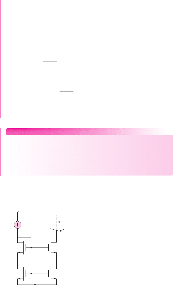
The value of the common-mode rejection ratio can be increased by increasing
the output resistance of the current source. An increase in the output resistance can
be accomplished by using a more sophisticated current source circuit. Figure 11.24
I
REF
V
–
V
+
M
1
M
3
M
2
I
Q
R
o
M
4
Figure 11.24 MOSFET cascode current source
nea80644_ch11_753-850.qxd 6/19/09 4:37 AM Page 786 pmath DATA-DISK:Desktop Folder:18.6.09:MHDQ134-11:

Chapter 11 Differential and Multistage Amplifiers 787
shows a MOSFET cascode current mirror that was discussed in the last chapter. The
output resistance, as given by Equation (10.57), is
R
o
= r
o4
+r
o2
(1 + g
m
r
o4
).
For
the parameters of Example 11.9,
r
o2
= r
o4
= 170 k
and
g
m
= 2
K
n
I
Q
=
1.53 mA/V
. Then
R
o
= 170 +170[1 +(1.53)(170)] ⇒ 44.6M
Again, using the parameters of Example 11.9, the common-mode voltage gain of
the diff-amp with a cascode current mirror would be
A
cm
=−
2K
n
I
Q
· R
D
1 + 2
2K
n
I
Q
· R
o
=−
√
2(1)(0.587) · (16)
1 + 2
√
2(1)(0.587) · (44600)
=−0.000179
so that the CMRR would be
CMRR
dB
= 20 log
10
8.67
0.000179
= 93.7dB
We increased the common-mode rejection ratio dramatically by using the cascode
current mirror instead of the single two-transistor current source. Note, however, that
the differential-mode voltage gain is unchanged.
To gain an appreciation of the difference in CMRR between 45.3 dB and
93.7 dB, we can reconsider the linear scale. For a CMRR
dB
= 45.3
dB, the differen-
tial gain is a factor of 185 times larger than the common-mode gain, while for a
CMRR
dB
= 93.7
dB, the differential gain is a factor of 48,436 times larger than the
common-mode gain.
Two-Sided Output
If we consider the two-sided output of an ideal MOSFET op-amp and define the out-
put voltage as
V
o
= V
d2
− V
d1
, we can show that the differential-mode voltage gain
is given by
A
d
= g
m
R
D
(11.84(a))
and the common-mode voltage gain is given by
A
cm
= 0
(11.84(b))
The result of
A
cm
= 0
for the two-sided output is a consequence of using matched
devices and elements in the diff-amp circuit. We will reconsider a two-sided output
and discuss the effects of mismatched elements in the next section.
Effect of R
D
Mismatch—Two-Sided Output
We assume that R
D1
and R
D2
are the resistors in the drains of M
1
and M
2
. If the two
resistors are not matched, we assume that we can write
R
D1
= R
D
+R
D
and
R
D2
= R
D
−R
D
.
Using the small-signal equivalent circuit in Figure 11.23, we
can find
A
d
= g
m
R
D
(11.85(a))
and
A
cm
∼
=
R
D
R
o
(11.85(b))
11.3.4
nea80644_ch11_753-850.qxd 6/19/09 4:37 AM Page 787 pmath DATA-DISK:Desktop Folder:18.6.09:MHDQ134-11: