Neamen D. Microelectronics: Circuit Analysis and Design
Подождите немного. Документ загружается.


808 Part 2 Analog Electronics
and the KCL equation is
V
π7
r
π7
=
V
π6
r
π6
+ g
m6
V
π6
(11.122(a))
or
V
π7
= r
π7
(1 + β)
r
π6
V
π6
= r
π7
(1 + β)I
b6
(11.122(b))
where
r
π6
g
m6
= β
. Substituting Equations (11.122(b)) and (11.121) into Equa-
tion (11.120), we obtain
V
b6
= I
b6
r
π6
+r
π7
(1 + β)I
b6
(11.123)
The input resistance is therefore
R
i
=
V
b6
I
b6
= r
π6
+r
π7
(1 + β)
(11.124)
Assuming
I
C7
= I
Q
, the hybrid-π parameters are
r
π7
=
βV
T
I
C7
=
βV
T
I
Q
(11.125(a))
and
r
π6
=
βV
T
I
C6
=
(1 + β)βV
T
I
Q
(11.125(b))
Combining Equations (11.125(a)), (11.125(b)), and Equation (11.124) yields an
expression for the input resistance, as follows:
R
i
=
(1 + β)βV
T
I
Q
+
(1 + β)βV
T
I
Q
=
2(1 + β)βV
T
I
Q
(11.126)
We can determine the small-signal voltage gain of the Darlington pair circuit by
using the small-signal equivalent circuit in Figure 11.47(b). We see that
v
o3
= i
c7
R
L7
= (βi
b7
)R
L7
= β(1 +β)i
b6
R
L7
(11.127)
and
i
b6
=
v
b6
R
i
(11.128)
The small-signal voltage gain is therefore
A
v
=
v
o3
v
b6
=
β(1 +β)R
L7
R
i
(11.129)
Substituting Equation (11.126) into (11.129), we find that
A
v
=
β(1 +β)R
L7
2(1 + β)βV
T
I
Q
=
I
Q
2V
T
R
L7
(11.130)
In Figure 11.46, we see that resistance R
L7
is the parallel combination of the
resistance looking into the collector of Q
11
and the resistance looking into the base of
Q
8
. From Chapter 10, the resistance looking into the collector of Q
11
is
R
c11
= r
o11
(1 + g
m11
R
E
)
(11.131)
nea80644_ch11_753-850.qxd 6/19/09 4:37 AM Page 808 pmath DATA-DISK:Desktop Folder:18.6.09:MHDQ134-11:

Chapter 11 Differential and Multistage Amplifiers 809
where
R
E
= r
π11
R
3
. The resistance looking into the base of Q
8
is
R
b8
= r
π8
+(1 +β)R
4
. (11.132)
Equations (11.131) and (11.132) indicate that resistances R
c11
and R
b8
are large,
which means that the effective resistance R
L7
is also large.
EXAMPLE 11.13
Objective: Calculate the input resistance and the small-signal voltage gain of a
Darlington pair.
Consider the circuit shown in Figure 11.46, with parameters
I
C7
= I
Q
=
0.2 mA,
I
C8
= 1
mA,
R
4
= 10 k
, and
R
3
= 0.2k
. Assume
β = 100
for all tran-
sistors, and the Early voltage for Q
11
is 100 V.
Solution: The input resistance, given by Equation (11.126), is
R
i
=
2(1 + β)βV
T
I
Q
=
2(101)(100)(0.026)
0.2
⇒ 2.63 M
The small-signal voltage gain is a function of R
L7
, which in turn is a function of R
c11
and R
b8
. We can find that
r
π11
= β V
T
/I
Q
= (100)(0.026)/0.2 = 13 k
such that
R
E
= 130.2 = 0.197 k
Also
g
m11
= I
Q
/V
T
= 0.2/0.026 = 7.69 mA/V
and
r
o11
= V
A
/I
Q
= 100/0.2 = 500 k
Therefore,
R
c11
= r
o11
(1 + g
m11
R
E
) = 500
[
1 + (7.69)(0.197)
]
⇒ 1.26 M
We can determine that
r
π8
= β V
T
/I
C8
= (100)(0.026)/1 = 2.6k
Then
R
b8
= r
π8
+(1 +β)R
4
= 2.6 +(101)(10) ⇒ 1.01 M
Consequently, resistance R
L7
is
R
L7
= R
c11
R
b8
= 1.261.01 = 0.561 M
nea80644_ch11_753-850.qxd 6/19/09 4:37 AM Page 809 pmath DATA-DISK:Desktop Folder:18.6.09:MHDQ134-11:

810 Part 2 Analog Electronics
Finally, from Equation (11.130), the small-signal voltage gain is
A
v
=
I
Q
2V
T
R
L7
=
0.2
2(0.026)
(561) = 2158
Comment: The input resistance of the Darlington pair is in the megohm range,
which should minimize severe loading effects on the diff-amp. In addition, the small-
signal gain is large because of the active load (Q
11
) and the large input resistance of
the emitter-follower output stage.
EXERCISE PROBLEM
Ex 11.13: Consider the Darlington pair Q
6
and Q
7
in Figure 11.46. Determine the
current gain of the Darlington pair,
I
c7
/I
b6
. Use the parameters described in
Example 11.13. (Ans.
(101)(100) = 1.01 ×10
4
)
We can use the results of Chapter 6 to determine the output resistance of the
emitter follower. The output resistance is
R
o
= R
4
r
π8
+ Z
(1 + β)
(11.133)
where Z is the equivalent impedance, or resistance, in the base of Q
8
. In this case,
Z = R
c11
R
c7
, where R
c7
is the resistance looking into the collector of Q
7
. Because
of the factor
(1 + β)
in the denominator, the output resistance of the emitter follower
is normally small, as previously determined.
EXAMPLE 11.14
Objective: Calculate the output resistance of the circuit in Figure 11.46.
Consider the same circuit and transistor parameters described in Example 11.13.
Assume the Early voltage of Q
7
is 100 V.
Solution: From Example 11.13, we have that
R
c11
= 1.26
M and
r
π8
= 2.6k
.
We can then determine that
R
c7
=
V
A
I
Q
=
100
0.2
= 500 k
Then,
Z = R
c11
R
c7
= 1260500 = 358 k
Therefore,
R
o
= R
4
r
π8
+ Z
(1 + β)
= 10
2.6 + 358
101
= 2.63 k
Comment: The output resistance is obviously less than R
4
and is substantially less
than the equivalent resistance Z in the base of Q
8
. In a later chapter, we will examine
a Darlington pair emitter-follower output stage in which the output resistance is on
the order of 100 .
nea80644_ch11_753-850.qxd 6/19/09 4:37 AM Page 810 pmath DATA-DISK:Desktop Folder:18.6.09:MHDQ134-11:
Chapter 11 Differential and Multistage Amplifiers 811
EXERCISE PROBLEM
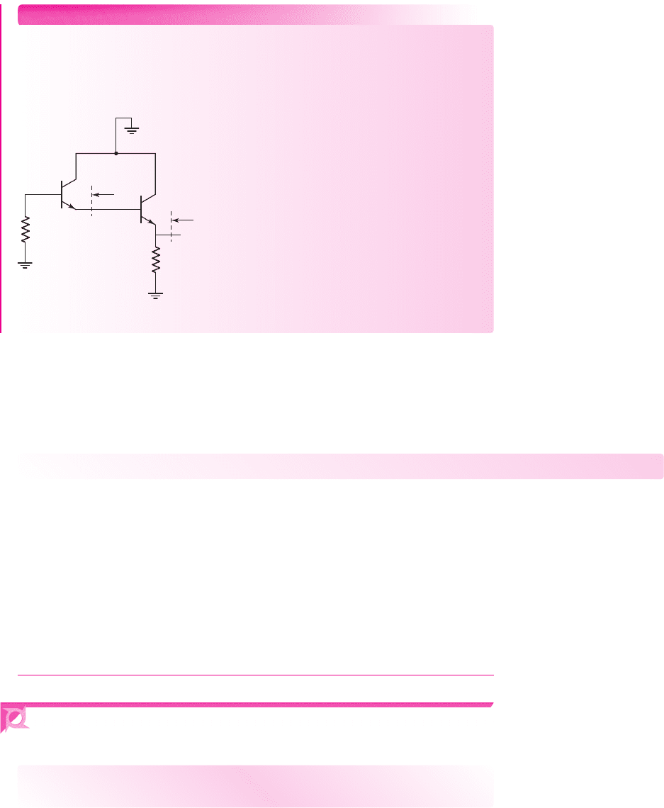
Ex 11.14: The circuit shown in Figure 11.48 is an ac equivalent circuit of a Dar-
lington pair output stage. Assume the transistor current gains are
β
A
= 90
and
β
B
= 180
. Assuming transistor
Q
B
is biased at
I
CQB
= 0.5
mA, determine the
output resistance
R
o
. (Ans.
R
o
= 120 )
Q
B
Q
A
300 kΩ
10 kΩ
R
o
R
oA
Figure 11.48 Figure for Exercise Ex11.14
A BJT diff-amp with an active load can produce a small-signal differential-
mode voltage gain on the order of 10
3
, and the Darlington pair can also provide a
voltage gain on the order of 10
3
. Since the emitter follower has a gain of essentially
unity, the overall voltage gain of the op-amp circuit is on the order of 10
6
. This value
is typical for the low-frequency, open-loop gain of op-amp circuits.
Test Your Understanding
TYU 11.18 Consider the Darlington pair and emitter-follower portions of the circuit
in Figure 11.46. The parameters are:
I
C7
= I
Q
= 0.5
mA,
I
C8
= 2
mA,
R
4
= 5k
,
and
R
3
= 0.1k
. For all transistors, the current gain is
β = 120
, and for Q
11
and Q
7
,
the Early voltage is
V
A
= 120
V. Calculate the input resistance and small-signal volt-
age gain of the Darlington pair, and the output resistance of the emitter follower.
(Ans.
R
i
= 1.51 M
,
A
v
= 3115
,
R
o
= 1.14 k
)
TYU 11.19 In the circuit in Figure 11.46, the Darlington pair and emitter-follower
transistor parameters are the same as in Exercise TYU 11.18. Determine the effective
resistance R
L7
(see Figure 11.47(a)) such that the small-signal voltage gain is 10
3
.
(Ans.
R
L7
= 104 k
)
11.7 SIMPLIFIED BJT OPERATIONAL
AMPLIFIER CIRCUIT
Objective: • Analyze a simplified multistage bipolar amplifier.
An operational amplifier (op-amp) is a multistage circuit composed of a differential
amplifier input stage, a gain stage, and an output stage. In this section, we will
consider a simplified BJT op-amp circuit.
nea80644_ch11_753-850.qxd 6/19/09 4:37 AM Page 811 pmath DATA-DISK:Desktop Folder:18.6.09:MHDQ134-11:
812 Part 2 Analog Electronics
Although active load devices increase the gain of an amplifier, in this discussion,
we will consider resistive loads, in order to simplify the analysis and design. For the
bipolar circuit, all component values are given; we will analyze both the dc and ac
circuit characteristics.
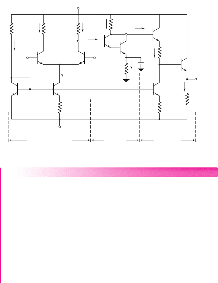
Figure 11.49. depicts a simple bipolar operational amplifier. The differential
amplifier stage is biased with a Widlar current source, and a one-sided output is
connected to the Darlington pair gain stage. An emitter bypass capacitor C
E
is
included to increase the small-signal voltage gain. The output stage is an emitter
follower. In general, we want the dc value of the output voltage to be zero when the
input voltage is zero. To accomplish this, we need to insert a dc level shifting circuit
between the voltage v
O3
and the output voltage v
O
.
I
Q
I
1
v
1
v
2
I
C1
v
O2
v
O3
v
O
I
C2
I
R5
I
R7
I
R6
I
R4
R
i2
R
i3
R
1
=
19.3 kΩ
R
7
=
5 kΩ
R
4
=
11.5 kΩ
R
6
=
16.5 kΩ
R
5
=
5 kΩ
R
2
=
59.6 Ω
R
3
=
59.6 Ω
V
–
= –10 V
V
+
= 10 V
R
C
= R
C
=
20 kΩ
C
E
20 kΩ
Q
1
Q
7
Q
2
Q
3
Q
4
Q
5
Q
8
Q
9
Q
6
Gain Stage Output StageDifferential Amplifier
Figure 11.49 Bipolar operational amplifier circuit
EXAMPLE 11.15
Objective: Analyze the dc characteristics of the bipolar op-amp circuit.
Consider the circuit in Figure 11.49. Neglect base currents and, as a simplification,
assume
V
BE
(on) = 0.7
V for all transistors except Q
8
and Q
9
in the Widlar circuit.
Solution: The reference current I
1
is
I
1
=
10 − 0.7 −(−10)
19.3
= 1mA
The bias current I
Q
is determined from
I
Q
R
2
= V
T
ln
I
1
I
Q
and is
I
Q
= 0.4mA
nea80644_ch11_753-850.qxd 6/19/09 4:37 AM Page 812 pmath DATA-DISK:Desktop Folder:18.6.09:MHDQ134-11:

Chapter 11 Differential and Multistage Amplifiers 813
The collector currents are then
I
C1
= I
C2
= 0.2mA
The dc voltage at the collector of Q
2
is
V
O2
= 10 − I
C2
R
C
= 10 −(0.2)(20) = 6V
With these circuit parameters, the common-mode input voltage is limited to the range
−8.6 ≤ v
CM
≤ 6V
, which will keep all transistors biased in the forward-active mode.
The current I
R4
is determined to be
I
R4
=
V
O2
−2V
BE
(on)
R
4
=
6 − 1.4
11.5
= 0.4mA
Since base currents are assumed negligible, the current I
R5
is
I
R5
∼
=
I
R4
.
The dc voltage at the collectors of Q
3
and Q
4
is then
V
O3
= 10 − I
R5
R
5
= 10 −(0.4)(5) = 8V
This shows us that the dc voltage V
O3
is midway between the 10 V supply voltage
and the dc input voltage
V
O2
= 6
V to Q
3
. This allows a maximum symmetrical
swing in the time-varying voltage at v
o3
.
Transistor Q
5
and resistor R
6
form the dc voltage level shifting function. Since
R
3
= R
2
, we have
I
R6
= I
Q
= 0.4mA
The dc voltage at the base of Q
6
is found to be
V
B6
= V
O3
− V
BE
(on) − I
R6
R
6
= 8 −0.7 −(0.4)(16.5) = 0.7V
This relationship produces a zero dc output voltage when a zero differential-mode
voltage is applied at the input.
Finally, current I
R7
is
I
R7
=
v
o
−(−10)
R
7
=
10
5
= 2mA
Comment: The dc analysis of this simplified op-amp circuit proceeds in much the
same way as in previous examples. We observe that all transistors are biased in
the forward-active mode.
EXERCISE PROBLEM
Ex 11.15: Consider the simple bipolar op-amp circuit in Figure 11.49. The tran-
sistor parameters are:
β = 100
,
V
BE
(on) = 0.7
V (except for Q
8
and Q
9
), and
V
A
=∞
. Redesign the circuit such that
I
C1
= I
C2
= 0.1
mA,
I
R7
= 5
mA,
I
1
=
I
R4
= I
R6
= 0.6
mA,
V
CE1
= V
CE2
= 4
V,
V
CE4
= 3
V, and
v
O
= 0
. (Ans.
R
1
=
32.2k
,
R
2
= 143
,
R
3
= 0
,
R
C
= 67 k
,
R
4
= 3.17 k
,
R
5
= 8.5k
,
R
6
= 5.83 k
, and
R
7
= 2k
)
EXAMPLE 11.16
Objective: Determine the small-signal differential-mode voltage gain of the bipolar
op-amp circuit.
Consider the circuit in Figure 11.49, with transistor parameters
β = 100
and
V
A
=∞
.
nea80644_ch11_753-850.qxd 6/19/09 5:40 AM Page 813 pmath DATA-DISK:Desktop Folder:18.6.09:MHDQ134-11:

814 Part 2 Analog Electronics
Solution: The overall differential-mode voltage gain can be written
A
d
= A
d1
· A
2
· A
3
=
v
o2
v
1
−v
2
·
v
o3
v
o2
·
v
o
v
o3
The overall small-signal voltage gain is the product of the individual stage gains only
if the load resistance of the following stage is taken into account.
We will rely on previous results to determine the individual voltage gains. The input
resistances to the Darlington pair R
i2
and to the output stage R
i3
are indicated in Figure
11.49. The one-sided differential-mode voltage gain of the diff-amp is given by
A
d1
=
V
o2
v
d
=
g
m
2
(R
C
R
i2
)
where
R
i2
is the input resistance of the Darlington pair, as follows:
R
i2
= r
π3
+(1 +β)r
π4
where
r
π4
= β V
T
/I
R4
= (100)(0.026)/0.4 = 6.5k
and
r
π3
∼
=
β
2
V
T
/I
R4
= (100)
2
(0.026)/0.4 = 650 k
Therefore,
R
i2
= 650 +(101)(6.5) = 1307 k
The transistor transconductance is
g
m
=
I
Q
2V
T
=
0.4
2(0.026)
= 7.70 mA/V
The gain of the differential amplifier stage is therefore
A
d1
=
g
m
2
(R
C
R
i2
) =
7.70
2
[201307] = 75.8
Since the load resistance
R
i2
R
C
, there is no significant loading effect of the sec-
ond stage on the diff-amp stage.
From previous results, we know the voltage gain of the Darlington pair is given by
A
2
=
I
R4
2V
T
(R
5
R
i3
)
where
R
i3
= r
π5
+(1 +β)[R
6
+r
π6
+(1 +β)R
7
]
We find that
r
π5
= β V
T
/I
R6
= (100)(0.026)/0.4 = 6.5k
and
r
π6
= β V
T
/I
R7
= (100)(0.026)/2 = 1.3k
Therefore
R
i3
= 6.5 +(101)[16.5 + 1.3 +(101)(5)] ⇒ 52.8M
Since
R
i3
R
5
, the output stage does not load down the gain stage, and the small-
signal voltage gain is approximately
A
2
∼
=
I
R4
2V
T
R
5
=
0.4
2(0.026)
(5) = 38.5
nea80644_ch11_753-850.qxd 6/19/09 4:37 AM Page 814 pmath DATA-DISK:Desktop Folder:18.6.09:MHDQ134-11:

Chapter 11 Differential and Multistage Amplifiers 815
The combination of Q
5
and Q
6
forms an emitter follower, and the gain of the output
stage is
A
3
= v
o
/v
o3
∼
=
1
The overall small-signal voltage gain is therefore
A
d
= A
d1
· A
2
· A
3
= (75.8)(38.5)(1) = 2918
Comment: From our previous discussion, we know that the overall gain can be
increased substantially by using active loads. Yet, the analysis of this simplified
circuit provides some insight into the design of multistage circuits, as well as the
overall small-signal voltage gain of op-amp circuits.
Computer Correlation: A PSpice analysis was performed on the bipolar op-amp
circuit in Figure 11.49. The dc output voltage from this analysis was
V
O
=
−0.333 V
, rather than the desired value of zero. This occurred because the B–E volt-
ages were not exactly 0.7 V, as assumed in the hand analysis. A zero output voltage
can be obtained by slightly adjusting R
6
. The differential voltage gain was
A
d
= 2932
, which agrees very well with the hand analysis.
EXERCISE PROBLEM
Ex 11.16: Consider the simple bipolar op-amp circuit in Figure 11.49 with circuit
and transistor parameters given in Exercise Problem Ex11.15. Determine the
input resistances R
i2
and R
i3
, and the differential-mode voltage gain
A
d
= v
o
/v
d
.
(Ans.
R
i2
= 870 k
,
R
i3
= 21.0M
,
A
d
= 11,729
)
Problem-Solving Technique: Multistage Circuits
1. Perform the dc analysis of the circuit to determine the small-signal parame-
ters of the transistors. In most cases BJT base currents can be neglected. This
assumption will normally provide sufficient accuracy for a hand analysis.
2. Perform the ac analysis on each stage of the circuit, taking into account the
loading effect of the following stage. (In many cases, previous results of
small-signal analyses can be used directly.)
3. The overall small-signal voltage gain or current gain is the product of the
gains of the individual stages as long as the loading effect of each stage is
taken into account.
11.8 DIFF-AMP FREQUENCY RESPONSE
Objective: • Analyze the frequency response of the differential
amplifier.
In Chapter 7, we considered the frequency responses of the three basic amplifier
configurations. In this section, we will analyze the frequency response of the differ-
ential amplifier. Since the diff-amp is a linear circuit, we can determine the frequency
nea80644_ch11_753-850.qxd 6/19/09 4:37 AM Page 815 pmath DATA-DISK:Desktop Folder:18.6.09:MHDQ134-11:
816 Part 2 Analog Electronics
response due to: (a) a pure differential-mode input signal, (b) a pure common-mode
input signal, and (c) the total or net result, using superposition.
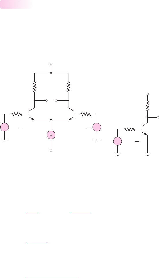
Due to Differential-Mode Input Signal
Consider the basic bipolar diff-amp shown in Figure 11.50(a). The input is a pure
differential-mode input signal. We know from Equation (11.24) that the small-signal
voltage v
e
is at signal ground when a differential-mode input signal is applied. To
determine the frequency response, we evaluate the equivalent common-emitter half-
circuit in Figure 11.50(b).
11.8.1
(a)
(b)
V
+
V
–
R
C
I
Q
R
B
R
B
Q
1
Q
2
R
C
v
O1
v
O2
v
e
v
1
=
v
d
2
v
2
= –
v
d
2
+
–
+
–
V
+
R
C
R
B
v
O1
v
1
= +
v
d
2
+
–
Figure 11.50 (a) BJT differential amplifier with differential-mode input signal and
(b) equivalent common-emitter half-circuit of differential amplifier
Since the diff-amp is a direct-coupled amplifier, the midband voltage gain
extends to zero frequency. This one-sided midband gain is
A
v1
=
V
o1
V
d
/2
=−g
m
R
C
r
π
r
π
+ R
B
(11.134(a))
or
A
v1
=
−β R
C
r
π
+ R
B
(11.134(b))
From the high-frequency common-emitter characteristics determined in Chap-
ter 7 we know that the upper 3 dB frequency is
f
H
=
1
2π[r
π
R
B
](C
π
+C
M
)
(11.135)
where C
M
is the equivalent Miller capacitance given by
C
M
= C
μ
(1 + g
m
R
C
)
(11.136)
Equation (11.136) implies that, if the value of R
C
is fairly large, the Miller
capacitance will significantly affect the bandwidth of the differential amplifier.
nea80644_ch11_753-850.qxd 6/19/09 4:37 AM Page 816 pmath DATA-DISK:Desktop Folder:18.6.09:MHDQ134-11:
Chapter 11 Differential and Multistage Amplifiers 817
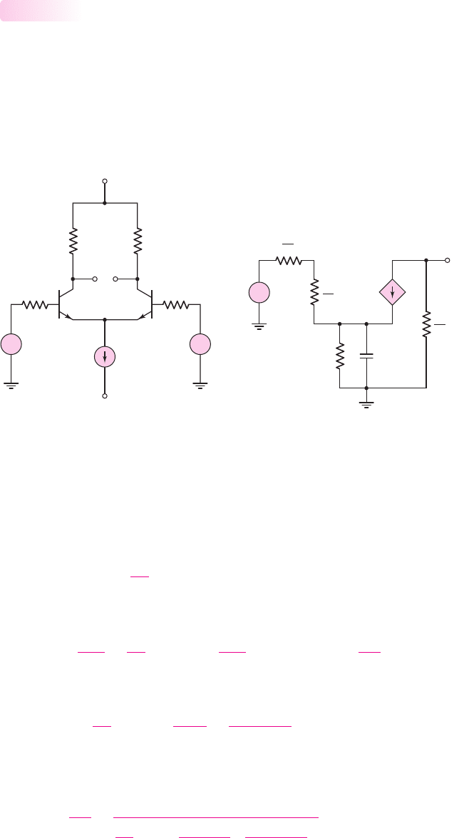
Due to Common-Mode Input Signal
Figure 11.51(a) shows the basic diff-amp with a pure common-mode input signal.
The circuit is symmetrical, which means that resistors R
B
, resistors R
C
, and the tran-
sistors are effectively in parallel. Figure 11.51(b) is the small-signal equivalent
circuit, with the constant-current source replaced by its output resistance R
o
and
capacitance C
o
.
11.8.2
(a)
(b)
V
+
V
–
R
C
R
C
Q
1
Q
2
R
B
R
B
I
Q
v
O1
v
O2
v
1
= v
cm
v
2
= v
cm
+
–
+
–
V
cm
2g
m
V
p
R
o
V
o
C
o
R
B
2
R
C
2
V
p
2
r
p
+
–
+
–
Figure 11.51 (a) BJT differential amplifier with common-mode input signal and
(b) small-signal equivalent circuit, common-mode configuration
We will justify neglecting the transistor parameters
C
π
and
C
μ
. The output volt-
age is
V
o
=−(2g
m
V
π
)
R
C
2
(11.137)
A KVL equation around the B–E loop produces
V
cm
=
V
π
r
π
/2
R
B
2
+ V
π
+
V
π
r
π
/2
+2g
m
V
π
R
o
1
sC
o
(11.138(a))
or
V
cm
= V
π
R
B
r
π
+1 +2
1 + β
r
π
R
o
1 + sR
o
C
o
(11.138(b))
Solving for
V
π
and substituting the result into Equation (11.137) yields the common-
mode gain, which is
A
cm
=
V
o
V
cm
=
−g
m
R
C
R
B
r
π
+1 +
2(1 + β)
r
π
R
o
1 + sR
o
C
o
(11.139(a))
nea80644_ch11_753-850.qxd 6/19/09 4:37 AM Page 817 pmath DATA-DISK:Desktop Folder:18.6.09:MHDQ134-11: