Schneider P., Eberly D.H. Geometric Tools for Computer Graphics
Подождите немного. Документ загружается.


504 Chapter 11 Intersection in 3D
existence of an intersection is whether the ray’s origin P is within the sphere, which
is true if the term (P −C) · (P −C) − r
2
is nonpositive.
In the case of a line segment, the same approach could be used, but instead
checking that the root or roots are bounded betwween 0 and 1, inclusive. A slightly
more efficient approach was suggested by Paul Bourke (1992): note that the closest
point on the line through P
0
P
1
to C is along a perpendicular from C to the line; in
other words, if Q is the closest point on the line, then
(C −Q) · (P
1
− P
0
) = 0
If we substitute the equation of the line into this, we get
(C −P
0
− u(P
1
− P
0
)) · (P
1
− P
0
) = 0
If we solve this, we get
u =
(C −P
0
) · (P
1
− P
0
)
(P
1
− P
0
) · (P
1
− P
0
)
If u<0oru>1, then the closest point is not within the bounds of the segment. If
there is an intersection (or intersections), then u ≤r. If both these tests succeed, then
we can compute the actual intersection as before.
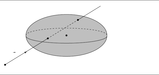
11.3.3 Linear Components and an Ellipsoid
This section addresses the intersection of linear components and an ellipsoid, as
shown in Figure 11.10.
The linear component L is represented in the usual fashion—as an origin point
P and direction
d:
L(t) = P + t
d
An ellipsoid is represented by a centerpoint C, a radius r, and three scaling
factors—one associated with each basis vector. The implicit form of this is
k(x − C
x
)
2
+ l(y − C
y
)
2
+ m(z − C
z
)
2
− r
2
= 0 (11.12)
If we substitute the (coordinate form of) the line equation into Equation 11.12,
we get
k(P
x
+ td
x
− C
x
)
2
+ l(P
y
+ td
y
− C
y
)
2
+ m(P
z
+ td
z
− C
z
)
2
− r
2
= 0
11.3 Linear Components and Quadric Surfaces 505
P
C
Q
0
Q
1
d
Figure 11.10 Intersection of a linear component and an ellipsoid.
This is a quadratic equation of the form
at
2
+ bt + c = 0
where
a =kd
2
x
+ ld
2
y
+ md
2
z
b = 2k(P
x
− C
x
)d
x
+ 2l(P
y
− C
y
)d
y
+ 2m(P
z
− C
z
)d
z
c = k(P
x
− C
x
)
2
+ l(P
y
− C
y
)
2
+ m(P
z
− C
z
)
2
.
As with the sphere, the number of intersections depends on the value of the discrim-
inant (see Section 11.3.2).
The pseudocode is
int LineEllipsoidIntersection(Ellipsoid e, line3D l, float t[2])
{
float a, b, c, discrm;
int numSoln = 0;
a = e.k * l.d.x^2 + e.l * l.d.y^2 + e.m * l.d.z^2;
b=2*k*(l.p.x - e.center.x) * l.d.x +2*l*(l.p.y -
e.center.y) * l.d.y+2*m*(l.p.z - e.center.z) * l.d.z;
c=k*(l.p.x - e.center.x)^2+l*(l.p.y - e.center.y)^2 +
m * (l.p.z - e.center.z)^2;
discrm=b*b-4*a*c;
506 Chapter 11 Intersection in 3D
if (discrm > 0) {
t[numSoln] = (-b + sqrt(discrm)) / (2 * a);
numSoln++;
t[numSoln] = (-b - sqrt(discrm)) / (2 * a);
numSoln++;
} else if (discrm == 0) {
t[0]=-b/(2*a);
numSoln++;
}
return numSoln;
}
An alternative approach is based on the idea that an ellipsoid is simply a sphere
that has been transformed by (nonuniform) scaling. If we invert this transformation,
the ellipsoid turns back into a sphere; if this same inverted transformation is applied
to the linear component, then we can simply find the intersection of the linear com-
ponent with a sphere, and then transform the intersection point(s) (if any) back. To
slightly simplify things, we can also translate the ellipsoid to the origin.
For an ellipsoid with scaling factors k, l, and m and center C, the matrix M that
transforms the ellipsoid into a sphere is
M =
1
k
000
0
1
l
00
00
1
m
0
−C
x
−C
y
−C
z
1
The linear component is then
L
(t) = P M + t
dM
and the ellipsoid is then
x
2
+ y
2
+ z
2
− r
2
= 0
giving us an intersection equation
(P
x
+ td
x
)
2
+ (P
y
+ td
y
)
2
+ (P
z
+ td
z
)
2
− r
2
= 0
which can be solved using the algorithm for linear component/sphere intersection
(note, though, that a small efficiency can be gained when the sphere’s center is the
origin, which may be worth exploiting).
The pseudocode is

11.3 Linear Components and Quadric Surfaces 507
int LineEllipsoidIntersection(Ellipsoid e, line3D l, Point3D Intersection[2])
{
float a, b, c, discrm;
int numSoln;
Line3D transformedl;
Sphere s;
Matrix4x4 M, MInv;
M = e.TransformMatrix();
transformedl.d = l.d * M;
transformedl.p = l.p * M;
s.radius = e.radius;
float t[2];
numSoln = lineSphereIntersection(s,transformedl,t)
if (numSoln > 0) {
MInv = M.Inverse();
}
for(i=0;i<numSoln ; i++) {
Intersection[i] = (transformedl.p + t[i] * transformedl.d ) * MInv;
}
return numSoln;
}
One final notational comment: you will frequently see an ellipsoid’s equation
given as
x −C
x
a
2
+
y −C
y
b
2
+
z − C
z
c
2
− r
2
= 0
which is equivalent to the one we used here, with k = 1/a
2
, l = 1/b
2
, and m = 1/c
2
.
If we use this other notation, then we can directly write down a parametric version of
the ellipsoid:
x =C
x
+ ar cos(θ ) cos(φ)
y =C
y
+ br cos(θ) sin(φ)
z = C
z
+ cr sin(θ)
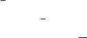
11.3.4 Linear Components and Cylinders
Typically, a graphics library or application will implement one of three representa-
tions for cylinders:
508 Chapter 11 Intersection in 3D
x
y
z
z
x
y
h
r
T
Figure 11.11 Parameterized standard cylinder representation.
Pure standard representation: The object’s base is at the origin, its axis is aligned
with one of the local frame’s basis vectors, and the radius and height are 1. Asso-
ciated with the object is a transformation matrix M that translates and rotates the
cylinder to the desired position and that scales its dimensions to give it arbitrary
size and proportions (as well as allowing for elliptical cylinders).
Parameterized standard representation: Similar to the “pure” representation, but
the radius and height are parameters, and the axis may be any one of the three
basis vectors of the local frame. Variations on this might allow for a specification
of a height, a ratio of radius to height, and so on. See Figure 11.11.
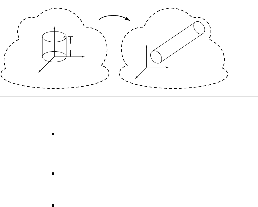
General representation: The cylinder is specified by a centerpoint C, an axis
vector ˆa,radiusr, and some scheme for specifying the extent of the cylinder (i.e.,
the location of the end caps). Extent specification varies from system to system,
but a typical approach is to put one end cap at C and another at a distance from
C (i.e., the height). See Figure 11.12.
We’ll give an algorithm for computing the intersection of linear components
with only a parameterized standard representation. An algorithm that can handle
the completely general case could also be employed for the standard representations,
and you could argue for that algorithm instead. You could also argue that if you have
transformed a standard cylinder to its world-space location, then ray intersection,
for example, wouldn’t require you to transform the ray into the cylinder’s local space,
and then transform the intersection point(s) back into world space. All this may be
true, but in nearly all 3D applications and libraries providing cylinders (and cones,
etc.), geometric objects are organized by a scene graph, in which transformations
are inherited down the tree. Because components like cylinders are located, sized,
11.3 Linear Components and Quadric Surfaces 509
C
r
h
â
Figure 11.12 General cylinder representation.
and oriented via a concatenation of transformations, you may as well transform the
component from a standard position.
Parameterized Standard Representation
Here, we represent a cylinder as having its base at the origin, its axis aligned with the
(local) z-axis, and a specified radius r and height h. In this case, the equation for the
cylinder becomes
x
2
+ y
2
= r
2
,0≤z ≤ h (11.13)
and the equations for the caps, which are on the z = 0 and z = h planes, are
x
2
+ y
2
≤ r
2
, z = 0, z = h
In order to intersect a line L(t) = P +t
d with such a cylinder, we need to trans-
form L by M
−1
(that is, back into the local space of the standard cylinder),
2
compute
the parameter t of the closest intersection point, and then plug t back into the line
equation to compute the actual intersection point in the line’s frame of reference.
2. To transform a parametric line equation L(t) = P + t
d, we apply the inverse of the trans-
formation to both the origin and the direction vector, remembering that the homogeneous
coordinate of a vector is 0: L
(t) = P M
−1
+ t
dM
−1
.
510 Chapter 11 Intersection in 3D
The intersection with the sides is trivial: substitute the line equation into Equa-
tion 11.13, yielding
(P
x
+ td
x
)
2
+ (P
y
+ td
y
)
2
− r
2
= 0
Expanding and collecting terms, we get
(d
2
x
+ d
2
y
)t
2
+ 2(d
x
P
x
+ d
y
P
y
)t + (P
2
x
+ P
2
y
) − r
2
= 0
As usual, this is a quadratic equation of the form
at
2
+ bt + c = 0
which can be solved with the quadratic formula
t =
b ±
√
b
2
− 4ac
2a
Once we have computed t, we plug it back into the line equation to compute the point
of intersection (again, in the local frame of reference for the cylinder). Note that the
intersection(s), if they exist, are those of the line and the infinite cylinder. In order
to compute only those intersections bounded by the end caps, we need to test the
resulting intersection point(s) against 0 ≤ z ≤ h.
Intersection with the end caps can be computed by computing the intersection of
the line with the planes in which the end caps lie and then checking if x
2
+ y
2
≤ r
2
.
The closest intersection is then simply the closest of all the valid intersection points.
The pseudocode is
bool LineCylinderIntersection(Cylinder c, Line3D l, Point3D closestIntersection)
{
Matrix4x4 transform, invTransform;
float a, b, c, discrm;
float t[4];
bool valid[4];
Line3D tline;
Point3D ipoint[4];
transform = c.transformMatrix();
invTransform = transform.Inverse();
tline.direction = l.direction * invTransform;
tline.origin = l.origin * invTransform;
a = (tline.direction.x + tline.direction.y) ^ 2;
b=2*(tline.direction.x * tline.origin.x + tline.direction.y * tline.origin.y);
11.3 Linear Components and Quadric Surfaces 511
c = tline.origin.x^2 + tline.origin.y^2 - c.radius^2;
discrm = b*b - 4*a*c;
if (discrm > 0) {
t[0] = (-b + sqrt(discrm) / (2 * a);
t[1] = (-b - sqrt(discrm) / (2 * a);
ipoint[0] = tline.origin + t[0] * tline.direction;
if (ipoint[0].z<0||ipoint[0].z > c.height) {
valid[0] = false;
} else {
valid[0] = true;
}
ipoint[1] = tline.origin + t[1] * tline.direction;
if (ipoint[1].z<0||ipoint[1].z > c.height) {
valid[1] = false;
} else {
valid[1] = true;
}
// Check end caps
Plane3D p1,p2;
p1.normal = [0,0,1];
p2.normal = [0,0,-1];
p1.point = [0,0,0];
p2.point = [0,0,c.height];
if (lineIntersectPlane(p1,tline,t[3])) {
ipoint[3] = tline.origin + t[3] * tline.direction;
float d = ipoint[3].x^2 + ipoint[3].y^2;
if (d < = c.radius^2 ) {
valid[3] = true;
} else {
valid[3] = false;
}
} else {
valid[3] = false;
}
if (lineIntersectPlane(p2,tline,t[4])) {
ipoint[4] = tline.origin + t[4] * tline.direction;
float d = ipoint[4].x^2 + ipoint[4].y^2;
if (d < = c.radius^2) {
valid[4] = true;
512 Chapter 11 Intersection in 3D
} else {
valid[4] = false;
}
} else {
valid[4] = false;
}
// Find smallest t of the valid intersection points
float mint = infinity;
int minIndex = 0;
bool hit = false;
for(i=0;i<4;i++) {
if (valid[i]) {
if (t[i] < mint) {
mint = t[i];
minIndex = i;
hit = true;
}
}
}
closestIntersection = transform*ipoint[minIndex];
return hit;
} else if (discrm == 0) {
// Ray is tangent to side, no need to check caps
t[0]=-b/(2*a);
ipoint[0] = tline.origin + t[0] * tline.direction;
if (ipoint[0].z > c.z || ipoint[0].z < 0) {
return 0;
}
closestIntersection = transform*ipoint[0];
return true;
}
return false;
}
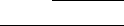
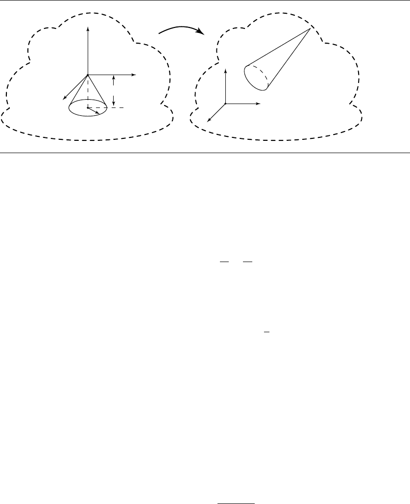
11.3.5 Linear Components and a Cone
As with the cylinder, a cone may be specified in some variation of a standard scheme
or in a fully general scheme (see Figures 11.13 and 11.14).
11.3 Linear Components and Quadric Surfaces 513
T
z
x
y
h
r
x
y
z
Figure 11.13 Parameterized standard cone representation.
Parameterized Standard Representation
The equation for a standard cone is
x
2
k
2
+
y
2
k
2
= z
2
where
−h ≤ z ≤ 0
k =
r
h
Its cap is represented by
z =−h
x
2
+ y
2
≤ r
2
Let the line be X(t) = P + t
d for t ∈ R. The cone has vertex V , axis direction
vector ˆa, and angle θ between axis and outer edge. In most applications, the cone is
acute, that is, θ ∈ (0, π/2). This section assumes that, in fact, the cone is acute, so
cos θ>0. The cone consists of those points X for which the angle between X −v
and ˆa is θ. Algebraically the condition is
ˆa ·
X − V
X − V
= cos θ