Seybold J.S. Introduction to RF Propagation
Подождите немного. Документ загружается.


Real-world components are sources of additional noise so that the overall
noise level is always greater than the theoretical value. For example, a receiver
adds noise of its own by the very presence of resistive elements in its
front end. Receiver noise can be characterized by either the effective noise
temperature or the noise figure (they are related). The actual noise power is
then
(4.9)
where F = (1 + T
e
/T
0
) is called the noise factor and T
e
is the equivalent
noise temperature of the receiver. This term, F, is generally referred to as the
noise figure, although, strictly speaking, the noise figure is the noise factor
expressed in dB.This misnomer is perpetuated in this text in conformance with
common usage. The reader should be sure to understand the distinction,
however.
The computation of the total noise power can also be performed in dB:
(4.10a)
or
(4.10b)
where F
dB
is the noise figure. The noise figure can also be defined as the ratio
of the input signal-to-noise ratio to the output signal-to-noise ratio. The two
definitions are equivalent, which is readily shown. Let
(4.11)
The signal-to-noise ratios are
Substituting these expressions into (4.11) yields
(4.12)
F
T
T
e
=+1
0
SNR
SNR
in
out
e
S
kT B
S
kT T B
=
=
+
()
0
0
F
in
out
=
SNR
SNR
NBF
dBm dB
=- +
()
+174 10dBm Hz log dB-Hz
NBF
dBW dB
=- +
()
+204 10dB- W Hz log dB-Hz
N kT B kT B
NkTBF
e
=+
=
0
0
watts
watts
72 COMMUNICATION SYSTEMS AND THE LINK BUDGET

Example 4.2. Given a receiver for a 10-megasymbol-per-second signal,
determine the available noise power present with the signal and find the noise
figure of the receiver if the equivalent noise temperature of the receiver is
870 K.
A 10 megasymbols per second data rate implies a noise-equivalent
bandwidth of approximately 10 MHz. The noise figure is determined using
(4.12) and is 4 (6 dB). The noise power present with the received signal will
be
䊐
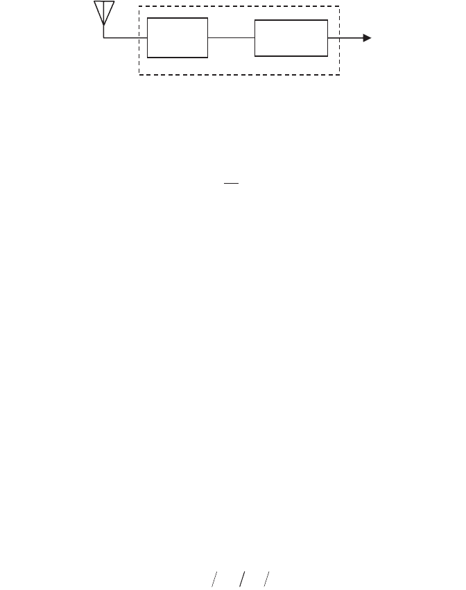
When there are several cascaded elements to be considered, the noise figure
of the composite system can be readily determined. First, consider the case of
two cascaded amplifiers as shown in Figure 4.2. Assume the system is driven
by a source whose impedance matches the first amplifier stage and whose noise
level is
The accompanying signal is S
in
. The output of the first stage will be
or
where T
e1
is the effective temperature of the first stage, referenced to the input.
The signal at the input to the second amplifier is the output of the first ampli-
fier, S
1
. To determine the output of the second amplifier, we add the apparent
noise of the second amplifier, which is characterized by T
0
+ T
e2
, and multiply
by the gain. Thus the output of the second amplifier is
or
S G G S G G kT BF G kT BF
in212 1201202
=+ +
SGSGGkTBFGkTTB
e22 2101202
=+ + +
()
1
S G S G kT BF
in11 101
=+
S G S G N G kT B
in in e11 1 11
=+ +
NkTB
in
=
0
NkTBF==-
0
128 dBW
NOISE 73
G1
G2
S
in
kT
0
B
G
1
S
in
G
1
G
2
S
in
G
1
kT
0
BF
1
G
1
G
2
kT
0
BF
1
+
G
2
kT
0
BF
2
Figure 4.2 Noise figure of two cascaded amplifiers.

To find the noise figure of the combined system, the definition of the noise
figure is applied:
so
or
(4.13)
Note that if
then
By applying mathematical induction, it can be shown that for any number of
cascaded amplifiers, the composite noise figure is given by
(4.14)
Based on the preceding analysis, it can be seen that the first stage of a well-
designed system sets the noise floor and thus must have the best noise per-
formance of all of the stages and relatively high gain. It is also apparent
that any losses prior to the first gain stage (usually a low-noise amplifier
or LNA) increase the noise figure. This can be understood by remembering
that the noise floor is set by the receiver characteristics (or the LNA) and thus
the noise is not reduced by the loss, but the signal is reduced; consequently,
the signal-to-noise ratio at the output is reduced, which decreases the noise
figure.
Any losses present between the antenna output and the receiver input
increase the overall noise figure of the system. For terrestrial systems, where
the input temperature is assumed to be the standard noise temperature of
290 K, the new noise figure is computed by simply adding the losses to the
receiver noise figure. This is seen in the following example.
FF
F
G
F
GG
F
GGG
total
=+ + + +
1
2
1
3
12
4
123
...
FF
total
⯝
1
GF
12
>>
FF
F
G
total
=+
1
2
1
F
SkTB
GG S GG kTB F F G
total
in
in
=
+
()
[]
0
12 12 0 1 2 1
F
SN
SN
in
out
=
()
()
74 COMMUNICATION SYSTEMS AND THE LINK BUDGET
Given that the cable loss is 7 dB and the noise equivalent temperature of the
receiver is 630 K, what is the noise figure of the receiver system?
The noise figure of the receiver alone is
So combining the receiver noise figure with the loss that precedes the receiver,
the noise figure of the entire receiver system is computed to be 12 dB.
Looking at the same problem from the signal-to-noise ratio perspective, let
the signal at the output of the antenna be denoted by S
1
and let the noise
density at the output of the antenna be
The signal-to-noise ratio at the input to the cable is S
1
/N
1
. The 7-dB cable loss
means that only 20% of the input power arrives at the output. Denoting the
signal at the output of the cable as S
2
,
The noise density at the output of the cable is based on the standard noise
temperature (since the cable is also a noise source), so
Thus the noise figure of the cable can be found:
or 7 dB as expected. Treating the receiver as a unity gain amplifier, one may
apply the cascade formula for noise figure to determine the overall noise
figure, which again is shown to be 12 dB. 䊐
It is important that only absorptive (resistive) losses be included in the system
noise figure computation. Gain reductions such as pointing error are not
FSNSN
cable
=
()()
=
11 22
5
NkTN
20
1
==
SS
21
02= .
NkT
1
=
0
F
T
T
e
=+ =15
0
dB
NOISE 75
Example 4.3. Consider the receiver system shown below.
Cable
Lo
ss
Receiver
treated as noisy attenuators since the noise is referenced to the input of the
receiving system.
There are many other sources of noise and loss that may be relevant to a
given application. Some examples are:
•
Local Oscillator (LO) Phase Noise. LOs are references for modulation
and demodulation of an information signal. Phase jitter within the LO
causes unintended spreading of the signal energy at both the transmis-
sion and receiving ends of a link. In most cases, spread components cannot
be recovered and may accounted for as a loss. In-band components are
seen as an increase in noise level.
•
AM-to-AM and AM-to-PM Conversion. System nonlinearities in the
transmitter or receiver may cause spurious amplitude variations and/or
phase variations in the signal. Depending on the nature of the nonlin-
earities, some of the signal may be spread out-of-band, resulting in an
overall signal loss.
•
Intermodulation Products. Some systems may use several carriers that
are amplified by a single wideband transmitter amplifier. Nonlinearities
in the amplifier result in the various carriers being multiplied, thereby
creating new signals at the sum and difference frequencies and at all com-
binations of the carrier frequencies. Here, too, the effects may be overall
signal loss and/or added in-band noise or loss.
•
Synchronization Loss. Imperfect synchronization results in degradation
in detector performance, and therefore a loss, and may also introduce
additional noise.
These noise sources are, in general, neither white nor Gaussian and may be
multiplicative rather than additive. Depending on the nature of these effects,
they may be accounted for as a system loss only—that is, an increase in the
minimum required E
b
/N
0
, RSL or received SNR.
The approach discussed in this chapter includes a standard noise tempera-
ture at the input. In satellite applications, the receiver may be sufficiently sen-
sitive that it sees the sky noise from the antenna rather than a 290 K noise
floor. In such applications, it is customary to use a total system temperature
rather than an effective temperature or a noise figure. This is covered in
Chapter 11, “Satellite communications.”
4.4 INTERFERENCE
Bandwidth limitation in the transmitter, receiver, and/or the channel itself may
cause pulse overlapping in time.Typically, most digital communication systems
have very stringent bandwidth allocations, and thus the digital pulses must be
carefully shaped at the transmitter to avoid channel spillover. As the filter
76 COMMUNICATION SYSTEMS AND THE LINK BUDGET
bandwidth becomes narrower and the cutoff sharper, the pulses tend to spread
in time, causing them to overlap. This is called intersymbol interference (ISI)
and can seriously degrade performance.
If multiple carriers are transmitted from the same transmitter, the nonlin-
earities can produce intermodulation products, which may be viewed as addi-
tional noise. Cripps [5] provides a good treatment of this subject. A similar
effect occurs if there is a strong adjacent channel signal overloading the
receiver and producing nonlinear operation [6]. In either case, the analysis (or
testing) is usually performed using two closely spaced tones of equal ampli-
tude. The nonlinearity produces spurs at various multiples, sums, and differ-
ences of the original two frequencies.
Another source of interference is external interference from other trans-
mitters. If the interference is at the same frequency as the signal of interest, it
is called co-channel interference. Co-channel interference may be caused by
harmonics from a different type of system, unintentional radiators, or signals
from a similar system that are some distance away (frequency sharing). In each
case, the interference is received within the operating bandwidth of the
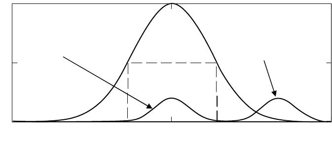
receiver as shown in Figure 4.3.
Interference that is near the frequency of the signal is called adjacent
channel interference and can be a problem depending upon the spectral prop-
erties of the receiver filter. If the filter skirts are not sufficiently attenuated,
the interference can cause undesired operation. This is shown graphically in
Figure 4.3. The normalized receiver filter response and its 3-dB bandwidth are
indicated along with representative spectra for co-channel and adjacent
channel interference. Since the co-channel interference enters the receiver at
or near the center of its bandwidth, the receiver filter does not attenuate it.
On the other hand, adjacent channel interference enters the receiver at a
nearby frequency and will be attenuated by the skirts of the receiver filter.
Thus a sharper roll-off on the receiver filter will reduce vulnerability to adja-
INTERFERENCE 77
0
0.5
1
Receiver Filter Response
3-dB Bandwidth
Co-Channel
Interference
Adjacent Channel
Interference
f
0
Figure 4.3 Receiver filter response with co- and adjacent channel interference.

cent channel interference, at the risk of possibly increasing the intersymbol
interference.
It is possible that interference can be of such a nature that it appears to be
externally generated noise. This is often how interference analysis is per-
formed. Most of the time, however, interference is not noise-like, which makes
precise performance analysis difficult. An exception is interference from spe-
cific systems, which can be carefully characterized on the bench to provide
some understanding of the signal interactions for different relative powers,
waveform timings, and frequency separations.
An interference margin term is included in the link budget. This term pro-
vides margin for noise floor degradation due to external interference. A 1-dB
interference margin means that the noise floor (noise plus interference) will
be as much as 1 dB higher than in a clear environment. The interference analy-
sis can then be performed on a link with the condition that the interference
must not degrade the noise floor by any more than 1 dB unless the interfer-
ence margin is increased in the link budget.
Example 4.4. Given a system whose link budget includes a 1-dB interference
margin, what is the maximum interference power at the input to the receiver
that can be tolerated?
If the noise floor (kT
0
BF) is N dBm, then the total noise plus interference
can be as large as N + 1 dBm. Of course the powers must be added in milli-
watts or watts, not dBm or dB. Let
and
where
n is the noise power in milliwatts
N is the noise power in dBm
i is the interference power in milliwatts
I is the interference in dBm
Then,
Solving for i, yields
in
in n
N
=-
=-
()
=
+
()
10
10 1 0 259
110
01.
.
Nni+= +
()
1 10 log
i
I
= 10
10
dBm
n
N
= 10
10
dBm
78 COMMUNICATION SYSTEMS AND THE LINK BUDGET

Converting back to dBm, the equation for the interference power is,
Thus a 1-dB interference margin requires that the total of all interference
power remains 5.9 dB or more below the noise floor. This is a useful rule of
thumb. 䊐
Intersymbol interference is another channel effect that can degrade the per-
formance of a digital communication system [7]. In the context of digital com-
munications, the channel refers to everything that is between the transmitting
and receiving modem, including RF mixers and other components, antennas
and cabling, and the actual propagation medium. Thus the channel is a super-
set of the propagation channel. Inter-symbol interference may be generated
in the transmitter, the receiver, the propagation channel, or any combination
thereof. The propagation mechanisms that produce ISI are discussed in later
chapters. The transmitter and receiver mechanisms that contribute to ISI are
related to spectral shaping. Improper transmit or receive spectral shaping can
produce symbols that overlap and interfere in time. The allocated margin for
ISI is usually included in the implementation loss figure and addressed as part
of modem design. For this reason, the ISI is not usually addressed by the link
designer as a source of noise.
It is possible for a nearby strong signal to interfere with receiver operation
even if it is well-filtered by the receiver and it does not overload (saturate)
the front end LNA. This can occur if the interference is outside of the
receiver’s instantaneous (detection) bandwidth, but within the tuning band-
width of the receiver. In this circumstance, the interfering signal may capture
or drive the front-end’s automatic gain control (AGC). When this occurs, the
receiver’s front-end gain is reduced to properly scale the interfering signal,
which can attenuate the desired signal. This is called de-sensing and must be
considered in configurations where other transmitters will be situated near the
receiver.
4.5 DETAILED LINK BUDGET
The link budget is the compilation of all gains and losses in the communica-
tion link [1]. By summing the transmit power in dBm (or dBW) with all of the
relevant link gains and losses in dB and then subtracting the required received
signal level (RSL, expressed in the same units as the transmit power), the link
margin in dB is obtained. The link margin provides a measure of robustness
for a link. Links with relatively small margins are not likely to be very robust
unless all of the gains and losses are very well understood and modeled. Some
of the losses in a link budget are based on availability requirements, and there-
fore the actual losses are not always present. Availability requirements can
drive some of the fade margins that are included in the link budget. In such
IN N=-
()
=-10 2 59 5 9log dBm..
DETAILED LINK BUDGET 79

circumstances a designer must account for losses that may be present inter-
mittently such as the attenuation due to rain or other precipitation in order
to ensure that the link is in fact available the required percentage of time. It
is important that the required fade margin be preserved if the true desired
availability is going to be maintained. This is discussed further in Chapter 10
on rain attenuation.
Figure 4.4 shows a typical link budget for a terrestrial millimeter-wave link.
It is customary to include relevant parameters in the link budget so that a
reader can reproduce the computations if desired. Thus, the frequency and
antenna polarization are included in the first few lines. Link budget formats
tend to be a religion, with little agreement on what is ideal or even necessary.
For that reason, the following example should be used as a guideline and not
necessarily as a template. The following sections closely examine each section
of the link budget in Figure 4.4, providing the details of the computations.
4.5.1 EIRP
After the first introductory lines of the link budget in 4.4, the next several lines
are dedicated to computing the transmitted EIRP. The EIRP is the transmit
power plus the antenna gain, minus any waveguide and/or radome losses.Thus
An allocation for loss due to impedance mismatch between the antenna and
the transmitter or HPA may also be included as a line item in this section, or
it may be included within the transmitter or antenna parameters. See Section
3.2.5 for details on impedance mismatch loss. The radome loss term may vary,
increasing when the radome is wet. The link budget must use the expected
worst-case value since the state of the radome is not known or controlled.
For the example link budget in Figure 4.4 the EIRP is calculated as
Of course the units of the EIRP will be the same as the units of the transmit-
ter power (dBW or dBm).
4.5.2 Path Loss
The path loss section includes the free space loss and all environmental effects
including multipath. Some of these effects are probabilistic while others
are deterministic. The free-space loss (or other computation of the geometric
loss) is a deterministic function of range. Atmospheric loss is a function of
range, the elevation angle of the link, and the local environment. A standard
atmosphere may be used to estimate the loss for all cases of interest with
acceptable error except at frequencies where the loss is considerable (e.g., 22
EIRP dBm dB dB dB dBm
dB
=+--=10 32 2 1 5 38 5..
EIRP dBm
dB TxdBm TxdB WGdB R
PGLL=+--
80 COMMUNICATION SYSTEMS AND THE LINK BUDGET

DETAILED LINK BUDGET 81
Frequency 38.6 GHz
Wavelength 0.0078 m
Polarization Vertical
Link Distance 2 km
Tx Power 10.0 dBm
Tx Loss –1.5 dB
Tx Antenna Gain 32.0 dB
Radome Loss –2.0 dB
EIRP 38.5 dBm
Path Loss (FSL) –130.2 dB
Tx Pointing Error –1.0 dB
Rain Loss (0.999) –15.0 dB
Multipath –2.0 dB
Atmospheric Loss –0.2 dB Gamma = 0.12 dB/km
Total Path Losses –148.4 dB
Radome Loss –2.0 dB
Rx Antenna Gain 32.0 dB
Polarization Loss –0.2 dB
Rx Loss –2.0 dB
Rx Pointing Error –1.0 dB
Total Rx Gain 26.8 dB
RSL –83.1 dBm
Interference margin –1.0 dB
Rx Noise Figure 7.0 dB
Noise Bandwidth 25.0 MHz
Total Noise Power –93.0 dBm
10log(kT
0
BF)
Signal-to-Noise Ratio 8.9 dB
Threshold –88.0 dBm
Net margin 3.9 dBm
Figure 4.4 Sample link budget.