Seybold J.S. Introduction to RF Propagation
Подождите немного. Документ загружается.

which yields a normalized average current value of (2/p)I
0
or 0.637I
0
. The
effective height is then found from (3.4):
Using the radiation resistance for a half-wave dipole, 73ohms [8], and the
impedance of free space, one can readily determine the effective area using
(3.5):
Note that this effective area has no direct relationship to the physical cross
section of the dipole antenna.That is to say, it does not depend upon the thick-
ness of the dipole, only its length. 䊐
3.2.3 Radiation Pattern
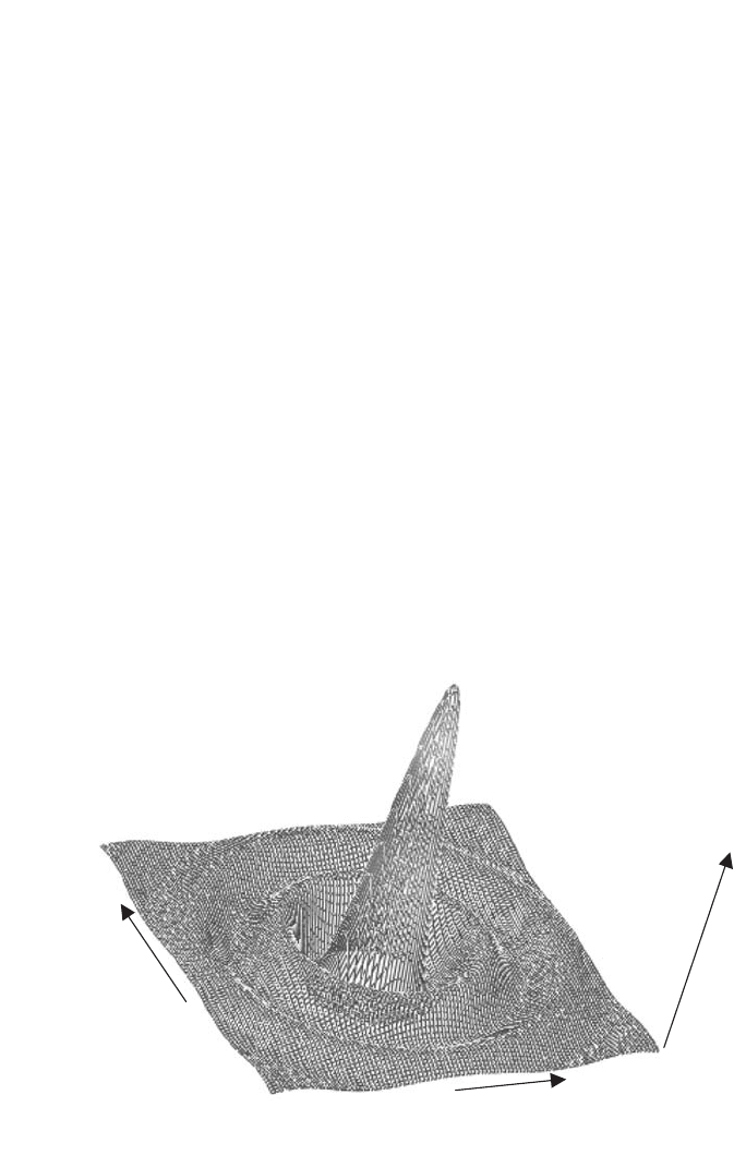
The radiation pattern of an antenna is a graphical depiction of the gain of the
antenna (usually expressed in dB) versus angle. Precisely speaking, this will be
a two-dimensional pattern, a function of both the azimuth and elevation
angles. This is illustrated in Figure 3.1 for a circular aperture antenna. In most
A
e
= 0 047.m
2
h
e
= 0 191.m
Ix I x
()
=
()
0
sin p
42 ANTENNA FUNDAMENTALS
Elevation Angle
Azimuth An
g
le
Gain
Figure 3.1 Three-dimensional plot of a two-dimensional antenna radiation pattern.
cases, however, looking at the principal plane cuts—that is, an azimuth pattern
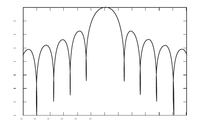
while bore-sighted in elevation and vice versa—is sufficient. Figure 3.2 shows
a typical principal plane pattern. Antenna patterns always describe the far-
field pattern, where the gain or directivity is a function of the azimuth and
elevation angles only and is independent of distance, d.
The mainlobe of the antenna is the lobe where the peak gain occurs. The
beamwidth of an antenna is defined as the angular distance between the two
points on the antenna pattern mainlobe that are 3 dB below the maximum gain
point. From Figure 3.2, the 3-dB beamwidth of that antenna may be estimated
to be about 5 degrees (±2.5). Another parameter that is often of considerable
interest is the maximum or peak sidelobe level.The pattern in Figure 3.2 shows
a maximum sidelobe level of about -17dB relative to the beam peak, which
has been normalized to 0-dB gain. Low sidelobes reduce the risk of undesired
signal radiation or reception, which can be valuable in high traffic or multi-
path environments. Sidelobe reduction is obtained, however, at the expense of
widening the mainlobe and reducing the antenna gain, or by increasing the
antenna size.
Another often-quoted specification of directional antennas is the front-to-
back ratio. This is the ratio of the antenna gain at 0 and 180 degrees azimuth
and provides an indication of how well the antenna will reject interfering
signals that arrive from the rear of the antenna. The front-to-back ratio is a
very important parameter when planning frequency reuse and interference
reduction.
ANTENNA PARAMETERS 43
30 25 20 15 1050 51015202530
80
70
60
50
40
30
20
10
0
Antenna Radiation Pattern
Angle (deg)
Gain (dB)
Figure 3.2 Typical antenna radiation pattern (normalized gain) in one dimension.
The antenna pattern of an aperture antenna is a function of the illumina-
tion taper across the aperture. The relationship between the spatial energy dis-
tribution across the aperture and the gain pattern versus angle is an inverse
Fourier transform [9]. Thus a uniformly illuminated aperture will produce the
narrowest main beam and highest possible gain at the expense of producing
sidelobes that are only 13 dB below the peak. By tapering the illumination
using a window function, the gain is slightly reduced (taper loss) and the main-
lobe is broadened, while the sidelobes are reduced in amplitude. Illumination
taper functions such as a raised cosine are often used to produce antennas with
acceptable sidelobes. Whenever an illumination taper is used, the resulting
antenna efficiency (and therefore gain) is reduced.
3.2.4 Polarization
Polarization is defined as the orientation of the plane that contains the electric
field component of the radiated waveform. In many cases, the polarization of
an antenna can be determined by inspection. For instance, a vertical whip
antenna generates and receives vertical polarization. Similarly, if the antenna
element is horizontal, the wave polarization will be horizontal. Vertical and
horizontal polarizations are both considered linear polarizations.Another type
of polarization is circular or elliptical polarization. Circular polarization is
similar to linear polarization, except that the polarization vector rotates either
clockwise or counterclockwise, producing right-hand circular or left-hand cir-
cular polarization. Circular polarization is a special case of elliptical polariza-
tion, where the vertical and horizontal components of the polarization vector
are of equal magnitude. In general, aperture antennas can support vertical, hor-
izontal, or elliptical polarization, depending upon the type of feed that is used.
3.2.5 Impedance and VSWR
An antenna presents a load impedance or driving point impedance to what-
ever system is connected to its terminals. The driving point impedance is
ideally equal to the radiation resistance of the antenna. In practical antennas,
the driving point impedance will also include resistive losses within the
antenna and other complex impedance contributors such as cabling and con-
nectors within the antenna. The driving point impedance of an antenna is
important in that a good impedance match between the circuit (such as a trans-
ceiver) and the antenna is required for maximum power transfer. Maximum
power transfer occurs when the circuit and antenna impedances are matched.*
Maximum power transfer is desirable for both transmitting and receiving.
44 ANTENNA FUNDAMENTALS
* Actually, maximum power transfer required a complex conjugate match. Most antenna systems
have real or nearly real driving point impedance, in which case a conjugate match and a match
are identical. An antenna connected to a cable with a characteristic impedance that is different
from its driving point impedance will present a complex impedance at the other end of the cable.
In such cases, a transmatch can be used to perform the conjugate matching.
When the antenna and circuit impedances are not matched, the result is
reduced antenna efficiency because part of the signal is reflected back to the
source. The square root of ratio of the reflected power to the incident power
is called the reflection coefficient.
Clearly, the reflection coefficient must be between zero and one (inclusive).
The reflection coefficient can be determined from the circuit and antenna
impedances,
(3.6)
The amount of signal passing between the transceiver and the antenna is
Thus the polarization mismatch loss is [10]
(3.7)
If there is a cable between the antenna and the transceiver, the mismatch
creates a voltage standing wave ratio (VSWR, or often just SWR) on the cable.
The effect of a VSWR on a cable is to increase the effect of the cable loss [11].
One way to compute theVSWR is
(3.8)
This can also be expressed in terms of the of antenna and transceiver charac-
teristic impedances.
Example 3.3. What is the reflection coefficient, VSWR and matching loss for
a 50-ohm transceiver driving a half-wave dipole?
The half-wave dipole has a characteristic impedance of 73 ohms, so the
reflection coefficient is ±0.23, depending upon the assignment of Z
1
and Z
0
.
The corresponding VSWR from (3.8) is 1.6. Applying (3.7), the matching loss
is found to be 0.947, or -0.24 dB, which is negligible in most applications. 䊐
3.3 ANTENNA RADIATION REGIONS
The antenna radiation field is divided into three distinct regions, where the
characteristics of the radiated wave are different. While these are not firm
VSWR =
1
1
+
-
r
r
L
p
=-1
2
r
PP
ti
=-
()
1
2
r
r=
-
+
ZZ
ZZ
10
10
r=
P
P
r
i
ANTENNA RADIATION REGIONS 45
boundaries, they represent convention usage and provide some insight to the
actual radiated field as a function of distance from the antenna.
The far-field (Fraunhoffer) region is defined for distances such that
(3.9)
where D is the largest linear dimension of the antenna, and l is the wave-
length. This is the region where the wavefront becomes approximately planar
(less than 22.5 degrees of phase curvature over a similar-sized aperture) [12].
In the far-field region, the gain of the antenna is a function only of angle (i.e.,
the antenna pattern is completely formed and does not vary with distance). In
the far field, the electric and magnetic field vectors are orthogonal to each
other. For electrically small antennas (D << l) the far-field boundary defined
by the preceding equation may actually fall within the near-field region. In
such cases, the far-field boundary should be taken as equal to the near-field
boundary rather than within it.
The radiating near-field is the region between the far-field region and the
reactive near-field region, also called the transition region.
(3.10)
In this region, the antenna pattern is taking shape but is not fully formed.Thus
the antenna gain will vary with distance even at a fixed angle. The radiated
wave front is still clearly curved (nonplanar) in this region and the electrical
and magnetic field vectors are not orthogonal.
The reactive near-field is defined as
(3.11)
This region is measured from the phase center or center of radiation of the
antenna and will be very close to the surface of the antenna. In general, objects
within this region will result in coupling with the antenna and distortion of the
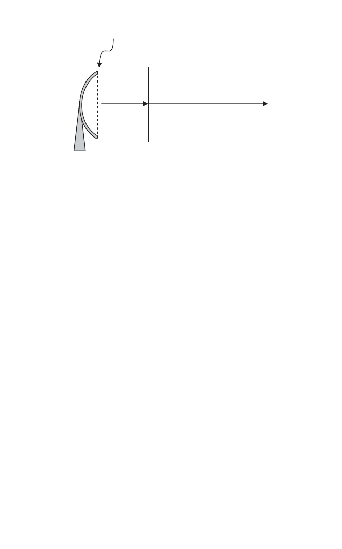
ultimate far-field antenna pattern. Figure 3.3 is an illustration of the radiation
regions for a reflector antenna.
Analysis of near-field coupling can be deceiving. It is unlikely that anything
will be close enough to a 40-GHz antenna to cause near-field coupling since
the wavelength is less than a centimeter, making the reactive near-field bound-
ary on the order of a couple of millimeters. On the other hand, it is very
difficult to avoid coupling with an HF antenna for amateur radio. Antennas
for the 75-m amateur radio band (4 MHz) have a reactive near-field boundary
of 12 m. Thus any large conductor (relative to the wavelength) within about
r <
l
p2
l
pl2
2
2
<<r
D
d
D
>
2
2
l
46 ANTENNA FUNDAMENTALS
39 ft of the antenna will couple with the antenna and “detune” it. The result
can be an altered resonant frequency, radiation resistance (defined shortly),
and/or radiation pattern. This can be a significant concern for radio amateurs
operating from small lots, where overhead utility lines, house gutters,
fascia trim, and other such items are difficult to avoid. Tying these conductors
to a good earth ground eliminates their resonant effect and mitigates their
impact.
Example 3.4. How much separation is required between a 140-MHz quarter-
wave monopole antenna and a 450-MHz quarter-wave monopole antenna if
both are mounted on the roof of an automobile and near-field coupling is to
be avoided?
To avoid mutual, near-field coupling, each antenna must be outside of the
reactive near-field of the other.The reactive near-field of the 140-MHz antenna
is larger than that of the 440-MHz antenna, so it determines the minimum
required separation.
where
The result is that the minimum required separation is
䊐
d
min
m= 0 341.
l=214.m
d
min
£
l
p2
ANTENNA RADIATION REGIONS 47
p
l
2
£d
Reactive Near-Field
Radiating
Near-Field
d = 2D
2
/
l
Far-Field
Regi
on
Figure 3.3 Typical boundaries for antenna radiation regions.
3.4 SOME COMMON ANTENNAS
The possible configurations of an antenna are limited only by the imagination.
In the field of electromagnetic compatibility, any conductor is a potential
radiator and may be treated as an antenna. In this section we examine
several broad categories of widely used antennas. The reader is directed to
the references for more detailed information on these antennas or for insight
into other antenna configurations.
3.4.1 The Dipole
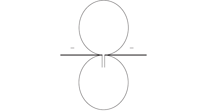
The half-wave dipole is configured as shown in Figure 3.4. It usually consists
of two segments, each one-quarter of a wavelength long, with the feed in the
middle, although offset-feed and end-fed dipoles are also used. The rings in
Figure 3.4 illustrate the directionality of the radiation pattern of the dipole. It
can be seen that there are areas of reduced gain off the ends of the elements.
The gain of a half-wave dipole is theoretically 2.14 dB. In general, antenna
gain may be specified in decibels relative to an isotropic radiator, dBi, or in
decibels relative to an ideal half-wave dipole, dBd.
The quarter-wave vertical or monopole antenna is one-quarter of a wave-
length long and is often (or at least ideally) mounted on an infinite, perfectly
reflective (conductive) ground plane. The ground plane provides a reflection
of the antenna, causing it to behave as a dipole antenna. Oftentimes in prac-
tical use, the “ground plane” turns out to be more of a lossy counterpoise (such
as the transceiver case and the hand and arm holding it), rather than a ground
plane that can provide an electrical image of the antenna. Even then, the
48 ANTENNA FUNDAMENTALS
4
l
4
l
Figure 3.4 The half-wave dipole antenna and its radiation pattern.
quarter-wave vertical antenna is still relatively effective. The counterpoise can
be thought of as a nonideal implementation of the other half of a half-wave
dipole.
The quarter-wave antenna may also be physically shortened as long as the
electrical length of l/4 is maintained. An example of such an antenna is the
flexible rubber duck or helix antenna [13] used on many handheld VHF and
UHF radios.While convenient, these antennas can have considerably less gain
than a regular quarter-wave antenna, on the order of -3 dB or more. All
quarter-wave antennas perform best when they have a large conductive
ground plane. Using the human hand and arm as a lossy counterpoise degrades
both the radiation pattern and the gain. If the antenna is held near the body
such as next to the head or on the waist, the net gain may be further reduced
by 10 dB or more.
An important parameter in antenna performance is the radiation resist-
ance. The radiation resistance of a resonant (half-wave) dipole is approxi-
mately 73 ohms, if it is center-fed. For an ideal antenna (no resistive losses),
the driving-point impedance seen by the transmitter or receiver is equal to the
radiation resistance. The same dipole can be end-fed, but the driving-point
impedance then becomes extremely large, on the order of 3000ohms.A match-
ing network of some type is then required to match the radiation resistance
to the feedline and receiver/transmitter impedance to avoid large reflections
and SWR (standing-wave ratio, also called voltage standing wave ratio or
VSWR). Such matching networks (transmatch) can be somewhat lossy and
reduce the efficiency of the antenna.
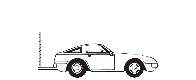
It is not unusual to see a “loading coil” at the base of an antenna, particu-
larly for mobile applications. This loading coil can be either an impedance
matching device if the radiator is an end-fed dipole, or it may be an inductor
that is used to increase the electrical length of the antenna. An example is the
“Hamstick” antenna used for HF work in automobiles. The antenna is a 4-ft
piece of fiberglass with windings running the entire length, forming what is
called a normal mode helix. At the top is a 3- to 4-ft whip that is adjusted in
length to tune the resonant frequency of the antenna. The body of the car
serves as a counterpoise, and the 8-ft antenna is then resonant at an HF fre-
quency such as 3.9MHz, giving it a resonant length of 75 m. This is shown con-
ceptually in Figure 3.5. Though the antenna is resonant, it does not have the
same gain as a full-length dipole and in fact its gain considerably less than
unity.
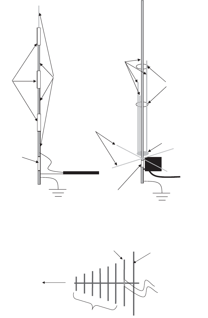
It is also possible to locate “traps” (tank or resonant circuits) along the
length of a radiator, so that the same vertical antenna can be resonant at
several spot frequencies. Such traps are resonant lumped elements. A trap
alters the electrical length of the antenna in one of two ways. It may be used
to cut off frequencies above its resonant frequency, so that the remainder of
the antenna is invisible above the resonant frequency. The other approach is
to have the trap resonance set in between two frequencies of interest, so that
at the higher frequency it becomes a capacitive load, effectively shortening the
SOME COMMON ANTENNAS 49
electrical length, and at the lower frequency it becomes an inductive load,
thereby increasing the electrical length. Another architecture for the multi-
band vertical antenna is a parallel array of closely spaced vertical radiators,
each tuned to a different band.The close proximity of the radiators means that
they have strong interaction, which alters the electrical length of the radiators,
so they do not physically measure a quarter- or a half-wavelength. The paral-
lel radiators are functioning as distributed elements. Both of these antenna
architectures are illustrated in Figure 3.6.
3.4.2 Beam Antennas
The half-wave dipole antenna also serves as a component of another popular
antenna, the Yagi-Uda (Yagi) beam antenna. The Yagi antenna is comprised
of a driven element, which is a center-fed half-wave dipole, a reflector element,
which is slightly longer than the driven element, and (optionally) several direc-
tor elements that are progressively smaller than the driven element. This is
shown in Figure 3.7. The boom may be conductive or nonconductive, with the
element lengths and antenna properties being slightly different in each case.
The Yagi beam is a directional antenna that generates a linearly polarized
wave. The gain and front-to-back ratio can be substantial if a long boom and
a sufficient number of elements are used in the design. Section 5.4 in Ref. 14
provides an excellent treatment of Yagi antenna design and analysis.
When mounted with the elements oriented vertically, the polarization
will be vertical and vice versa. Conventional television broadcast signals are
horizontally polarized, which is why television beam antennas are mounted
with the elements oriented horizontally. Horizontal polarization was chosen
for television broadcast because man-made interference tends to be vertically
polarized. By using horizontal polarization, television receivers have less
interference to contend with. Mobile radio uses vertical polarization primarily
for convenience because it is difficult to mount a horizontally polarized
50 ANTENNA FUNDAMENTALS
Figure 3.5 Base-loaded mobile HF antenna.
SOME COMMON ANTENNAS 51
Insulator
Shielded Coaxial
Feedline
Trap
s
Radiators
Conductive Support
Insulating Supports
Insulator
Matching Network
Shielded Coaxial
Feedline
Radiator
s
Electrical
Counterpoises
Figure 3.6 Four-band quarter-wave trap vertical and a four-band half-wave parallel
radiator vertical antenna.
Reflector
Driven Element
Directors
Direction of
maximum gain
Figure 3.7 A typical Yagi-Uda antenna (the taper in the element lengths has been
exaggerated in this picture for clarity).