Seybold J.S. Introduction to RF Propagation
Подождите немного. Документ загружается.

This is approximate because the actual resolution depends on the pulse shape
as well as the duration. Shorter pulses require larger receive bandwidths (more
noise) and provide less average power (less signal) but better range resolu-
tion. The matched filter has an impulse response that matches the transmitted
pulse. The range to the target is
(5.11)
where Dt is the elapsed time between transmission and reception of the pulse.
In a pulse or pulse-Doppler radar, the pulses are usually transmitted peri-
odically. This period is called the pulse-repetition interval (PRI) or the pulse-
repetition time (PRT). The term pulse repetition period has historically been
used as well, but it is not always appropriate since the pulses are not always
strictly periodic. The pulse repetition frequency is
The PRI defines the maximum unambiguous range of the system:
(5.12)
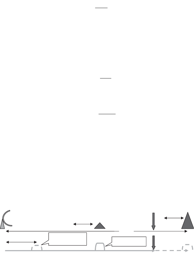
A large target beyond the unambiguous range may be interpreted as a
closer target. This occurs when the radar is listening for the return of the nth
pulse and actually receives a return from the (n - 1)th pulse. This is called a
multiple-time-around echo, and Figure 5.2 shows a diagram of how this can
occur.
For multiple-time-around returns to be an issue, the RCS of the distant
reflector must be sufficiently large so that the reflection can overcome the
additional path loss and still be detected. Ideally, R
unamb
should be well beyond
R
c
unamb
=
◊ PRI
2
PRF
PRI
∫
1
R
ct
=
◊D
2
92 RADAR SYSTEMS
R
0
– R
unamb
Multiple time
around return
Nth pulse
Range
R
unam
R
0
Target return
(N – 1)th pulse
Figure 5.2 Depiction of radar range ambiguities for pulsed radar.

the maximum detection range of the radar so that even large targets will not
provide a large enough return to be detected (maximum detection range is
defined for a given target RCS). In practice, this is not always practical, but
there are ways to mitigate the effect of range ambiguities. One technique is to
stagger the PRI’s. If the PRI is different from one pulse to the next, the true
target returns will remain stationary from one PRI to the next, while the
ambiguous returns will appear at a different range for each different PRI and
can thereby be eliminated from consideration.
5.3 RADAR MEASUREMENTS
Radar has progressed from a means of detection and ranging to a sensor
system that can provide complete position and velocity information on a target
as well as potentially imaging the target. The actual measurement can be
broken down into range measurement, angle measurement (azimuth and ele-
vation angle), and signature measurement (high-range and cross-range reso-
lution imaging of a target). The basic technology employed for each of these
types of measurements is discussed in the sections that follow.
5.3.1 Range Measurement
The most basic method of range measurement using a pulse radar is to simply
identify which range gate (receiver time sample) contains the majority of the
target energy. This provides a range measurement resolution on the order of
the pulse width:
To improve the range resolution without having to resort to extremely short
pulses (which increases the bandwidth required and raises the thermal noise
floor), pulse compression may be used. Pulse compression consists of further
modulating the radar signal within the transmit pulse. This can be done by
chirping the RF frequency or by applying a BPSK modulation with low auto-
correlation sidelobes. The result is a substantial increase of the range resolu-
tion of the radar without shortening the transmit pulse.
Another approach to enhanced range resolution is using a stepped fre-
quency sequence of pulses, which are then Fourier-transformed to provide a
high-range resolution profile of the target [12]. This approach is often used in
millimeter-wave radar systems and is frequently used in conjunction with syn-
thetic aperture techniques to provide two-dimensional high-resolution target
images.
A less exotic means of improving range measurement resolution is to
simply interpolate between adjacent range gates that contain the target
energy. A similar approach for tracking radar is called the split gate tracker,
DRc=t2
RADAR MEASUREMENTS 93
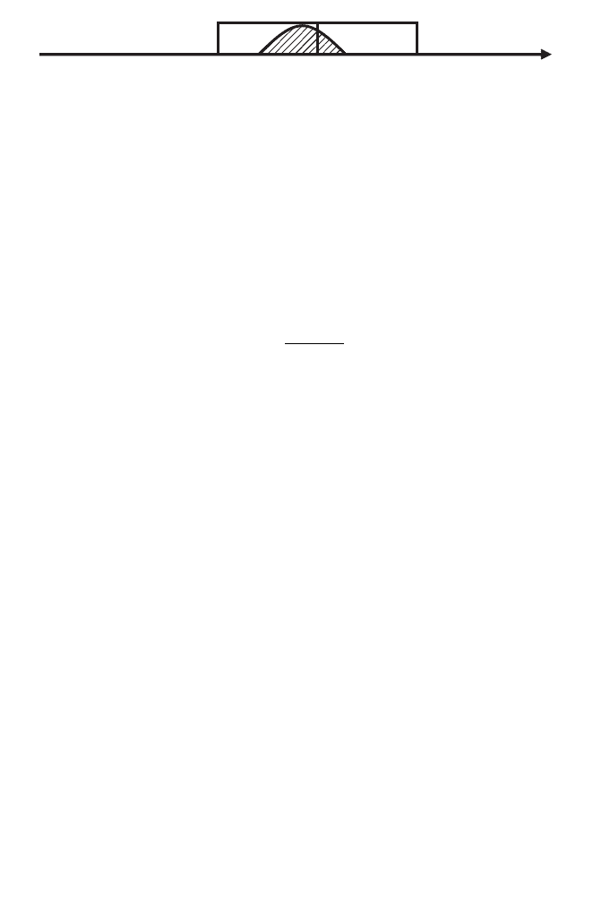
where the radar positions a pair of range gates straddling the target [13]. Figure
5.3 shows a diagram of a split gate tracker that is straddling a target return
with some range error. By comparing the energy in each range gate and divid-
ing by the sum of the energy in each range gate, an error signal can be gen-
erated to determine how much to move the range gates to straddle the target.
The error signal is
(5.13)
where
E
1
is the received energy in the early gate
E
2
is the received energy in the late gate
t is the length of each range gate
Dt is the additional time shift required to center the range gates over the
target
As mentioned earlier, the pulse width is one factor in determining how much
energy actually reaches the target to be reflected back to the radar.The actual
transmit energy is the peak power of the transmitter multiplied by the width
of the transmitted pulse.The peak envelope power (PEP) is referred to as peak
power in radar. It is still an average power in the sense that the output signal
is squared and averaged over an integer number of periods of the carrier, and
it does not mean the maximum instantaneous power within a period of the
carrier frequency. The average power as used in radar actually refers to the
peak power multiplied by the transmit duty cycle. That is, the peak power is
averaged over a transmit pulse, and the average power is averaged over the
entire pulse repetition interval. The normalized (R = 1 W) peak power of a
pulse radar is given by
where t is the pulse width and v(t) is the voltage at the radar output.The radar
average power is given by
Pvtdt
peak
=
()
Ú
2
0
t
Dt
EE
EE
=
-
+
12
12
t
94 RADAR SYSTEMS
Range
Early Gate Late Gate
Target Return
Figure 5.3 Split-gate tracking in range.

where T is the PRI, v(t) is the voltage at the radar output, and t is the pulse
width. When the power of a radar is specified, it usually refers to the peak
power and not the average power. This is because radar systems often employ
many different PRIs and pulse widths.
5.3.2 Doppler Measurement
Target velocity can be measured by estimating the Doppler shift on the return
signal. This is accomplished by collecting a series of returns and then applying
a discrete Fourier transform to them. For ground-based (stationary) radars,
the zero Doppler line is often removed to mitigate the effect of ground clutter.
By looking at the Doppler cell where the target appears, the direction and
magnitude of the target’s radial velocity can be determined. The Doppler res-
olution is determined by the number of pulse returns used for the Fourier
transform. More precisely, it is determined by the total time duration covered
by the radar samples. The Doppler extent is limited by the PRF or spacing
between pulses. If the target velocity exceeds the maximum of the transform,
the Doppler is aliased. This is called velocity or Doppler ambiguity and is
similar to the concept of range ambiguity. Some radar systems use an estimate
of target velocity based on successive range measurements rather than using
Doppler processing. This can be useful if sufficient information for Doppler
processing is not available.
5.3.3 Angle Measurement
For angle measurements with precision greater than the antenna beamwidth,
various beam-splitting techniques must be used. Sequential lobing consists of
squinting the beam slightly above and below and then to the left and right of
the tracking point. The return from each position is then used to update the
estimated target position in azimuth and elevation. Conical scan uses a con-
tinuous circular scan about the track point to develop a tracking error signal.
Both of these techniques are subject to tracking error due to noise, target fluc-
tuation, and electronic countermeasures. As a remedy, monopulse was devel-
oped. Monopulse uses the result of a single pulse to estimate both the azimuth
and elevation error in the antenna position relative to the target.This is accom-
plished by using a split aperture antenna that actually receives four distinct
beams simultaneously. Thus any pulse-to-pulse amplitude variations are elim-
inated as a source of angle measurement error.
There are different types of monopulse [14, 15], including amplitude and
phase monopulse. Standard angle tracking is usually accomplished with ampli-
tude monopulse. For simplicity, consider the amplitude monopulse case in one
Pvtdt
T
P
ave
T
peak
=
()
=
Ú
2
0
t
RADAR MEASUREMENTS 95
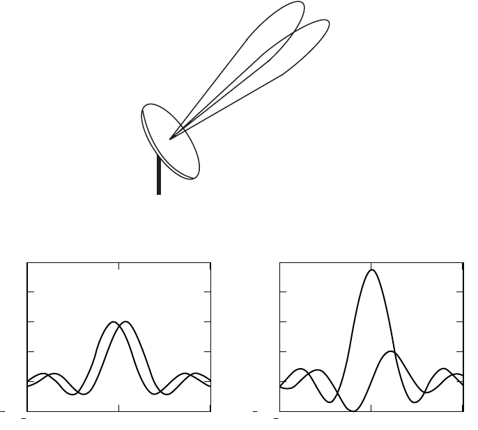
dimension. Two identical beams, squinted in angle, are generated from the
same aperture simultaneously by using a specialized feed or phased array. The
angle between the two beams is only a fraction of a beamwidth. This is
shown pictorially in Figure 5.4, for a single dimension. The signals from the
two beams are added and subtracted to produce a sum and a difference
pattern. The addition and subtraction can be done in the signal processor, or
it may be performed at RF using a hybrid junction such as Magic-Tee [16] or
similar device.
When a return signal is received, the samples from the sum and difference
patterns are represented by S and D, respectively. For that reason, the patterns
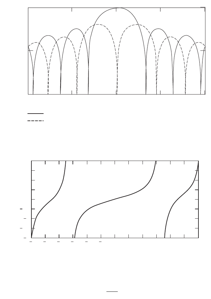
themselves are sometimes referred to as sum and delta patterns. Figure 5.5
shows a representative pair of individual beams and the corresponding sum
and difference patterns.The same curves, expressed in dB, are shown in Figure
5.6.This is the conventional way of expressing the sum and difference patterns.
The angle of the target from bore-sight is given by the ratio of delta to sum.
Both values are complex, so the denominator is rationalized.
96 RADAR SYSTEMS
Figure 5.4 Squinted antenna beams for monopulse radar.
10 0 10
0.25
0
0.25
0.5
0.75
1
10 0
10
0.25
0
0.25
0.5
0.75
1
Figure 5.5 Overlapping beams and the corresponding sum and difference beams.
(5.14)
where k is a calibration constant that depends upon the actual beam shapes
and angular separation of the two beams. Of course the actual values must
be used in this expression, not the dB values. Figure 5.7 shows what the
monopulse ratio looks like for this theoretical antenna. For the plot, the value
e=k
DS
SS
*
*
RADAR MEASUREMENTS 97
–10 –5 0 5 10
–30
–15
Sum
Difference
Sum and Delta Patterns Superimposed
Angle
Amplitude in dB
0
Figure 5.6 Sum and difference patterns in dB.
6 5 4 3 210 1234 56
2
1.5
1
0.5
0
0.5
1
1.5
2
Monopulse Delta/Sum
Angle
Monopulse Ratio
Figure 5.7 Monopulse ratio for the theoretical antenna.
of k is unity. The actual value is chosen to make the slope of the linear part of
the curve unity so that angle error is read out directly. It is interesting to note
that if enough error is present, the monopulse ratio has other angles where
the error slope is positive. It is possible for a radar to see and actually track a
target in these regions if it is strong enough to be detected in the sidelobe. This
is called sidelobe lock or sidelobe tracking. Tactical systems use various tech-
niques such as a wide-angle spotting antenna to preclude sidelobe lock.
As stated earlier, monopulse angle measurements are very robust to signal
amplitude fluctuations because all of the data comes from the same pulse. The
effect of noise on the monopulse ratio is not as well behaved, however. A the-
oretical analysis shows that the variance of the monopulse ratio is infinite in
the presence of Gaussian noise [17–19]. This is due to the fact that there
is a finite probability of S being arbitrarily close to zero. This fact is not of
great practical concern because measurements that are that weak will be dis-
carded. It does, however, accurately suggest that monopulse is susceptible to
jamming by white noise. For that reason, regular monopulse cannot be used
to track a noise source. Instead, the two beams must be processed separately,
and the detected power in each must be used to determine the angle tracking
error.
5.3.4 Signature Measurement
Many modern radar systems employ radar signature measurement techniques
to permit the radar to identify targets. The most basic type of signature meas-
urement is the high-range resolution profile. If multiple profiles are coherently
collected and stored with regular azimuthal spacing, it is possible to generate
a cross-range profile for each cell and the range profile [20]. This produces a
two-dimensional map of the target. The results can be used for target identi-
fication, system diagnostics, terrain mapping, and other remote sensing appli-
cations. The azimuthal spacing is ideally in angle, with the radar moving in an
arc whose focus is at the target, or a stationary radar viewing a target rotat-
ing at a constant angular velocity. In many applications, the motion is lateral
instead of angular, but it is possible to correct for the difference and still gen-
erate very high quality images.
The preceding technique is called synthetic aperture radar (SAR) if the
target is stationary or inverse synthetic aperture radar (ISAR) if the radar is
static and target rotation is used to produce the required changes in perspec-
tive. The images from SAR or ISAR processing are range/azimuth images. The
dimension of height can also be added by processing a set of coherent range-
azimuth maps taken at different elevation perspectives [21]. This method is
principally used for instrumentation purposes because the required setup, cal-
ibration, and data processing preclude most other applications. This is called
three-dimensional ISAR. Some radar systems also perform a monopulse
measurement on the contents of each resolution cell in a range-azimuth map
to provide limited information on the height of the scatter(s) in each cell. This
98 RADAR SYSTEMS
is also sometimes called three-dimensional ISAR, but that is a misnomer since
there is not actually any resolution in elevation, but rather a single composite
value.
5.4 CLUTTER
Clutter is defined as any unwanted radar echo. For a weather radar system, an
aircraft might be considered clutter; similarly, for a terrain mapping radar, a
vehicle in the field of view would be considered clutter. For the purposes of
this chapter, it is assumed that a vehicle or aircraft is the desired target and
that the natural reflectors in the scene represent clutter. Radar returns from
ground targets will include reflected energy from ground clutter—that is, the
surrounding terrain and vegetation. This type of clutter is called area clutter
since it is predominantly two-dimensional in nature. The amount of clutter
depends on the resolution of the radar in range and angle and the terrain char-
acteristics, as will be shown.
Airborne target returns seen by upward-looking radar may include volume
clutter from moisture or hydrometeors in the propagation path. Another
source of volume clutter is intentional clutter such as chaff (small metallic
strips) dispersed by an aircraft to overwhelm the radar receiver and conceal
the presence of aircraft. Chaff is an example of a radar countermeasure, but
it is treated as clutter since the effect is the same. Volume clutter as its name
implies is three-dimensional in nature. An upward looking radar may also
experience ground (area) clutter returns entering through the antenna side-
lobes. For moderately powered, ground-based radar, this can be a significant
source of (stationary) clutter.
In addition to estimating the mean clutter return signal, the radar designer
must take into account the statistics of the clutter. Some clutter such as
uniform terrain or calm water may have very little variation, whereas rough
terrain may have considerable spatial variation and tall vegetation or bodies
of water in heavy wind will also show significant temporal variation.
When designing a radar system for operation in a clutter environment, the
signal-to-clutter ratio (SCR) and the clutter-to-noise ratio (CNR) are of inter-
est. The SCR provides a measure of the expected target signal strength versus
the expected clutter return strength, which is used for detection analysis and
prediction. The CNR provides an indication of whether target detection is
limited by noise or limited by the external clutter.
5.4.1 Area Clutter
Area clutter, which is synonymous with ground clutter, is characterized by the
average clutter cross section per unit area, s
0
(sigma-zero). This parameter is
called the backscatter coefficient, and the units are m
2
/m
2
.The amount of clutter
received depends upon the backscatter coefficient and how much of the
CLUTTER 99
ground area is illuminated. The backscatter coefficient of clutter depends on
the grazing angle.
If the extent of the ground clutter is larger than the radar footprint, then
the width of the clutter patch is defined by the antenna azimuth beamwidth
and the range or distance to the clutter patch. The (down-range) length of the
clutter patch is determined by either the range gate size for shallow grazing
angles, or by the elevation beamwidth for steeper grazing angles [22].
The width of the clutter cell is
(5.15)
where R is the range to the center of the clutter cell and q
AZ
is the two-way
antenna azimuth beamwidth in radians. The two-way beamwidth is used
because the same beam is illuminating and then receiving the reflection from
the clutter. Another definition of the two-way beamwidth is the -1.5-dB
beamwidth of the antenna pattern. The concept of the width of the ground
clutter cell is illustrated in Figure 5.8. The depth or length of the clutter cell is
determined by the smaller of the range gate projected onto the ground, or the
elevation beamwidth times the total range projected onto the ground.
Thus the length of the clutter cell can be expressed as
(5.16)
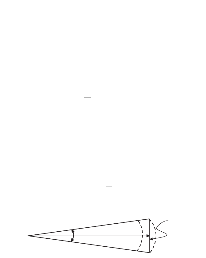
Figure 5.9 shows the geometry for the low grazing angle case where the range
gate size determines the down-range dimension of the clutter area. At higher
grazing angles, the antenna elevation pattern becomes the limiting factor as
illustrated in Figure 5.10. For the high grazing angle case, the two-way eleva-
tion beamwidth must be used rather than the one-way beamwidth, just as was
done in the range-gate-limited case with the azimuth beamwidth.
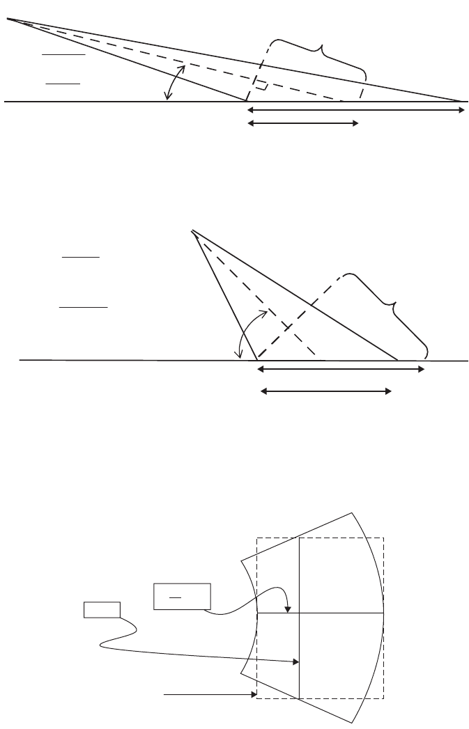
So at shallow grazing angles, where the clutter cell size is pulse-limited,
Figure 5.11 applies and
(5.17)
AR
c
cAZ
@
()
q
t
y
2
sec
l
c
R
EL
ª
() ()
Ê
Ë
ˆ
¯
min sec csc
t
yq y
2
,
WR
AZ
@q
100 RADAR SYSTEMS
q
AZ
W ªR
q
AZ
Top Down View
Radar
R
Figure 5.8 Determination of total illuminated clutter area.
CLUTTER 101
y
y = grazing angle
2cos(
y)
L
RG
L
RG
L
BW
L
BW
t
c
=
ct/2
sin(
y)
q
EL
R
◊
=
Radar
Figure 5.9 Range-gate-limited clutter area.
ct/2
)cos(2
y
t
c
=
y
y = grazing angle
)sin(
y
q
EL
R
◊
=
Radar
L
BW
L
BW
L
RG
L
RG
Figure 5.10 Beam-limited clutter area.
Actual Clutter Area
Estimated Clutter Area
W = Rq
AZ
l =
ct
sec(y )
2
Figure 5.11 Shape of range-gate-limited clutter cell.