Seybold J.S. Introduction to RF Propagation
Подождите немного. Документ загружается.


antenna on a automobile or a handset, but also because of its reflective
properties.
3.4.3 Horn Antennas
A horn antenna can be thought of as a flared end of a waveguide. A horn
antenna is one example of an aperture antenna. The polarization of the
emitted signal is dependent upon the polarization of the waveguide trans-
ducer. There are various shapes of horn antennas, and the taper of the flare
and the aperture size control the resulting radiation pattern. Horn antennas
can provide very high gain and narrow beams, depending upon their design.
They are frequently used as gain or calibration standards since their gains are
very predictable and repeateable.
3.4.4 Reflector Antennas
Reflector antennas include the parabolic reflector or dish antenna and the
Cassegrain antenna. The parabolic reflector has a receiver/transmitter
mounted in a small unit that is usually located at the focal point of the para-
bolic dish. In addition to the efficiency loss due to illumination taper, the sup-
ports for the antenna feed produce blockage in the antenna field of view. This
causes shadowing and produces diffraction lobes in the antenna pattern. An
offset feed can be used to reduce the shadowing effect of the feed supports.
An example of a parabolic dish antenna with an offset feed is the direct broad-
cast TV antenna as shown in Figure 3.8. The antenna feed (actually it is only
a receive antenna) contains a low-noise amplifier and a broadband (block)
down-converter that shifts all of the signals to L-band. The feed unit is there-
fore referred to as a low-noise block (LNB). The block of L-band signals then
travels through the coaxial cable to the receiver, which selects the desired fre-
quency for demodulation.
It is interesting that Direct TV broadcasts different programming simul-
taneously on right and left circular polarizations.The Direct TV receiver sends
52 ANTENNA FUNDAMENTALS
Feed Support
Reflector
LNB
LNB Lens
Figure 3.8 Offset feed reflector antenna for direct broadcast satellite TV.
a DC voltage over the receive signal coax to power the electronics in the LNB.
The level of the DC also tells the block converter which polarization to receive
based on the operator’s channel selection at the receiver. This is why Direct
TV receivers cannot directly share an antenna connection. For two receivers,
a dual LNB is employed, with a separate cable running to each receiver. For
more than two receivers, a dual LNB and a receiver control unit (multiswitch)
are used to provide the appropriately polarized signal to each receiver,
depending upon the channel being viewed. This is an example of frequency
sharing by using polarization diversity.
For some applications, the receiver/transmitter unit is mounted behind the
antenna with waveguide or coax cable connecting it to the center-mounted
feed. Of course, this configuration entails cable or waveguide loss as the signal
is fed to and from the feed point, so it is not suitable for most higher-frequency
applications. One way to eliminate this additional loss is to employ a
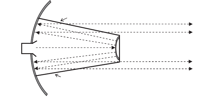
Cassegrain antenna, which is shown diagrammatically in Figure 3.9. The
Cassegrain antenna also employs a parabolic reflector, but it has the antenna
feed mounted in the center of the dish, where the signal radiates out to a sub-
reflector that is mounted at the focal point of the parabolic reflector.The signal
from the reflector then illuminates the dish and produces the radiation pattern.
One advantage of the Cassegrain antenna over the basic parabolic reflector is
that the receiver/transmitter unit can be mounted on the antenna without
using cables or waveguides and are not required to be as small as those for a
standard reflector antenna. Another advantage for very sensitive systems used
on earth stations for satellite communication is that the sidelobes from the
feed see sky rather than earth (since the feed is pointed upward), which
reduces the antenna temperature and thereby the receiver noise floor. The
center reflector still requires support, so the Cassegrain antenna also experi-
ences blockage and diffraction lobes both from the subreflector supports and
SOME COMMON ANTENNAS 53
Feed Horn
Main Reflector
Subreflector Support
Subreflector
Subreflector Support
Figure 3.9 Cassegrain antenna configuration.
the subreflector itself. There are many different ways that the supports can be
mounted, Figure 3.9 shows one possibility.
3.4.5 Phased Arrays
Phased array antennas were initially developed for large ground-based track-
ing radars. They provide the ability to focus a beam on each target in the field
of view in rapid succession without requiring rapid repositioning of the aper-
ture. The phased array is an array of radiating elements each with a control-
lable phase shifter. The antenna controller adjusts the phase (and sometimes
also the gain) of each element to provide the desired beam position and
beamwidth while controlling the sidelobes. Some systems even produce
multiple beams simultaneously. Phased arrays suffer from a phenomenon
called grating lobes when the look angle approaches 90 degrees off-boresight,
which is why phased arrays sometimes include physical pointing. The beam-
forming process uses digital signal processing techniques in the spatial domain
to form beams and control sidelobes. Squinted beams can be formed to permit
monopulse angle measurement.
As electronics have become increasingly powerful, efficient, and affordable,
phased arrays have found application in many other areas. So-called smart
antennas [15] have been used for GPS receivers and mobile telephone base
stations for interference control. The advantage of the phased array is that it
can steer a null in the direction of any detected interference, improving
receiver operation. This is often accomplished using an adaptive algorithm to
optimize signal-to-interference ratio.
3.4.6 Other Antennas
There are a multitude of antenna types, all of which cannot be even listed here.
Some of the more noteworthy configurations are discussed. One interesting
antenna is the magnetic field antenna. Most antennas are electric field anten-
nas; they work by intercepting the electrical field component of the desired
wave and converting it to a voltage that is sent to a receiver. It is equally pos-
sible to detect the magnetic field rather than the electric field, and it is some-
times advantageous to do so. One good example of a magnetic field antenna
is the ferrite loop antenna in a small AM radio. The wavelength of AM broad-
cast is so long that electric field antennas are difficult to fabricate with any
efficiency. Early AM radios required very long wire antennas. Later, as the
receiver became more sensitive, moderately sized loop antennas where
employed. Modern AM receivers use a ferrite rod with windings to sense the
magnetic field of the AM wave and provide a signal to the receiver.
Lens antennas operate just as the name suggests. They are treated as an
aperture antenna, but a lens covers the aperture and focuses the beam. The
lenses are often made of plastic, but other materials can be used as long as
they have the appropriate refractive properties at the frequency of interest.
54 ANTENNA FUNDAMENTALS

Patch antennas are conformal elements, which are useful for applications
where a low profile is required. An array of patch radiators can be used to
form a beam. Such antennas are useful for mobile and particularly airborne
applications, where low profile equates to less wind resistance and lower fuel
costs.
3.5 ANTENNA POLARIZATION
Antenna polarization is defined as the polarization of the electromagnetic
wave that it radiates. Polarization is defined in the far-field of the antenna and
is the orientation of the plane that contains the electric field portion of the
wave. In the far-field, the electrical field, magnetic field, and propagation direc-
tion vectors are all mutually orthogonal. This mutual orthogonality permits
complete characterization of a wave by describing the electric field vector and
the direction of propagation.
Most antennas and electromagnetic waves have either linear polarization
(vertical or horizontal) or circular polarization, which can be right-hand or
left-hand. In a general sense, all polarizations can be considered as special
cases of elliptical polarization. This provides a convenient mathematical
framework for looking at the effects of polarization. An elliptically polarized
wave can be expressed as [16]
where
and
are the x and y components of the E field vector. E is the vector that describes
the electric field as a function of time and position along the z axis (direction
of propagation). E
1
and E
2
are the amplitude of the linearly polarized wave in
the x and y directions. The d term describes the relative phase between the
x and y components of the electric field vector. If d is equal to zero, E will
be linearly polarized, with the orientation of its electrical field determined by
xE
1
+ yE
2
. If E
1
and E
2
are of equal magnitude and d=±90 degrees, then the
wave is circularly polarized. Circular polarizations, and elliptical polarizations
in general, are defined as follows (Figure 3.10):
Right-Hand Circular Polarization. Clockwise rotation when viewed in the
direction of propagation—that is, from behind (z into page).
EE tz
y
=-+
()
2
sin wbd
EE tz
x
=-
()
1
sin wb
Ex y=+EE
xy
ANTENNA POLARIZATION 55
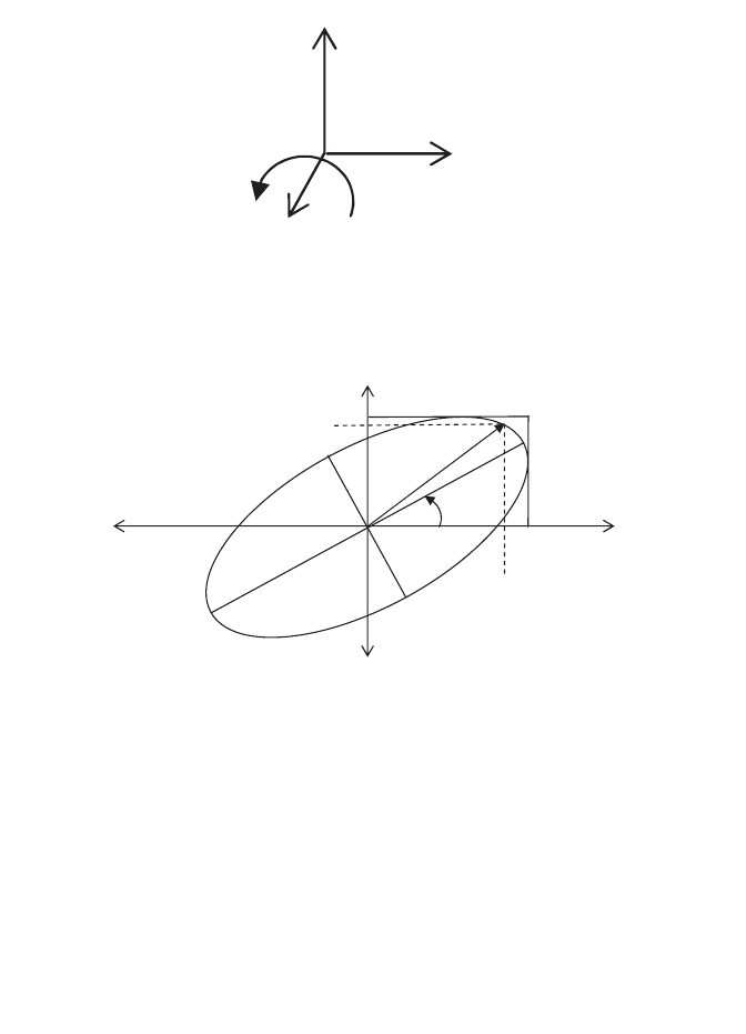
Left-Hand Circular Polarization. Counterclockwise rotation when viewed
from behind (z into page).
These definitions correspond to the IEEE definitions [17, 18]. The labels are
frequently shortened to right-circular and left-circular polarization. Using the
definitions and the preceding equation, it is straightforward to verify that
Figure 3.11 shows the polarization ellipse as presented by Ref. 16. Note that
E
1
and E
2
are the peak amplitudes in the x and y direction and are therefore
fixed, whereas E
x
and E
y
are the instantaneous amplitudes of the x and y com-
ponents, which are functions of time, t, position, z, and the relative phase, d.
This diagram makes it easy to visualize the following: If E
2
is zero (or if d is
d=- ∞Æ90 Right circular polarization
d=+ ∞Æ ∞
()
90 Left circular polarization leads by 90yx
56 ANTENNA FUNDAMENTALS
x E
x
y E
y
z
Figure 3.10 Relationship between orthogonal components of the E field and the
direction of propagation for right circular polarization (d=-90 degrees).
E
1
x
y
E
x
E
2
E
y
Tilt
Angle t
Figure 3.11 The polarization ellipse (Figure 2.22 from Ref. 16, courtesy of
McGraw-Hill.)
zero), the polarization is linear horizontal; and if E
1
is zero, it is vertical polar-
ization. The tilt angle, t, is the orientation of the major axis of the polarization
ellipse relative to the x axis.
The axial ratio is an important antenna parameter that describes the shape
of the polarization ellipse. The axial ratio is defined as the ratio of the major
axis to minor axis of the polarization ellipse when the phase angle between
the linear polarization components, d, is ±90 degrees. The axial ratio is always
greater than or equal to one. Since it is a ratio of amplitudes, it can be
expressed in dB using 20 log(AR). For precise applications such as satellite
communication, the axial ratio is given for circularly polarized antennas,
as a metric of the antenna’s deviation from ideal circular polarization. This
is valuable for determining the potential cross-coupling between an incident
wave and the orthogonal polarization channel of the receive antenna and
the coupling loss between an incident wave and the receive antenna at
the same polarization. Strictly speaking, if the axial ratio is anything other
than 0 dB, the antenna is elliptically polarized, but it is common to refer to
real-world antennas as circularly polarized with an axial ratio slightly greater
than 0 dB.
When an antenna polarization is orthogonal to that of an incident wave, it
will theoretically not receive any power from the incident wave. Examples of
this are a vertically polarized wave incident on a horizontally polarized
antenna or the Direct TV example of RCP and LCP waves being simultane-
ously incident on the antenna and only one or the other is actually sent to the
receiver. Of course, real-world antennas and waves are not perfect, so it is valu-
able to be able to determine how much energy from an incident wave is
coupled to the antenna. In the cross-polarization case, this is characterized by
the cross-polarization discrimination (XPD). In the co-polarization scenario,
if the polarizations do not match exactly, not all of the incident energy is
coupled to the antenna. This is characterized by the polarization loss factor,
F. Both of these parameters can be determined from the orientation and axial
ratio of the wave and the antenna.
3.5.1 Cross-Polarization Discrimination
In some systems, orthogonal polarizations are used to provide two channels
in the same frequency band. This may happen for example on a satellite com-
munication system where both left and right circular polarizations are trans-
mitted to the ground at the same frequency, and each earth station must
receive the appropriate polarization. Any cross-polarization leakage is con-
sidered co-channel interference. Cross-polarization discrimination or isolation
can be computed for either linear or circular polarizations. For fixed terres-
trial links, it is possible to employ polarization diversity to increase frequency
reuse, since the orientation of the polarization vectors can be carefully con-
trolled. For satellite communication systems, polarization diversity requires
the use of circular polarization since absolute control of the polarization vector
ANTENNA POLARIZATION 57

orientation is difficult, due to the geometry and the potential for Faraday rota-
tion in the ionosphere.
An important distinction that must be made is that technically the cross-
polarization discrimination is between the incident wave and the receive
antenna, not between the transmit and receive antennas [17]. The distinction
is due to the fact that there may be environmental effects on the trans-
mitted wave prior to reception. In most practical applications, however, the
parameters of the transmit antenna are used either directly or with some
allowance for environmental effects. For the linear polarization case, the cross-
polarization discrimination is a function of the angle difference between the
incident wave polarization vector and the receive antenna polarization vector.
This is referred to as the tilt angle and often designated as t. The amount of
cross-polarization discrimination is then given by
Cross-polarization discrimination for linear polarization can be thought of as
a special case of circular or elliptical polarization. For elliptical polarization,
the cross-polarization discrimination is a function of the tilt angle t and of the
axial ratios of the incident wave and the receive antenna. For linear polariza-
tion, the axial ratio is ideally infinite since the minor axis of the ellipse is zero.
Thus linear polarization and circular polarization can both be viewed as
special cases of elliptical polarization.
3.5.2 Polarization Loss Factor
The polarization loss factor is the multiplier that dictates what portion of the
incident power is coupled into the receive antenna.The polarization loss factor
will often be less than one because of polarization mismatch. The received
power is given by
where P
i
is the incident power and P
r
is the power actually available at the
antenna. The polarization loss factor is the complement of cross-polarization
discrimination. Just as with XPD, the polarization loss factor for linear polar-
ization is a degenerate case of the elliptical polarization case, where the polar-
ization ellipse collapses into a line. For linear polarization,
where t is the angle between the wave polarization and the receive antenna
polarization. F is a power ratio, so it is converted to dB using 10 log(F). It is
apparent that when t is zero, F = 1 and all of the incident power is received.
F =
()
cos
2
t
PFP
ri
=
XPD = sin
2
t
()
58 ANTENNA FUNDAMENTALS

When t is 90 degrees the polarization of the wave and the receive antenna are
orthogonal and no power is transferred. From the expressions for XPD and F
for linear polarization, it is clear that
as expected based on conservation of energy.
The general development of polarization loss factor is based on elliptical
polarization. Kraus [19] provides a development of the polarization loss factor
as a function of the axial ratios and tilt angle using the Poncaire¢ sphere, the
results of which are summarized here. The coordinates of the polarization
vector on the sphere are
where t is the tilt angle as defined earlier and
with
k = 1 for left-hand polarization
k =-1 for right-hand polarization
The great-circle angle to the polarization vector is given by 2g, where
and the equator-to-great-circle angle is d as previously defined. The polariza-
tion loss factor is defined as
where 2g
r
and 2g
w
are the great-circle angles to the receive antenna polariza-
tion vector and the wave polarization vector, respectively.
get
get
rrr
www
=
()()()
=
()()()
-
-
1
2
1
2
1
1
cos cos 2 cos 2
cos cos 2 cos 2
F
rw
=-
()
cos
2
gg
get=
() ()()
-
1
2
1
cos cos 2 cos 2
e=
()
-
tan
1
kAR
Longitude
Latitude
=
=
2
2
t
e
XPD =-1 F
ANTENNA POLARIZATION 59

It is common practice to let either t
r
or t
w
be zero and the other term then
accounts for the net tilt angle between the wave and the antenna. Making the
appropriate substitutions, it is possible to derive an expression for polariza-
tion loss as a function of g
r
, g
w
, and t:
(3.12)
An equivalent and perhaps easier-to-use formulation is given in Ref. 17:
(3.13)
In each case, the polarization loss factor applies to the received power.
Some interesting observations can be made from the preceding expression.
If both the incident wave and the antenna are circular (AR = 1), then F
defaults to unity as expected, regardless of the tilt angle. On the other
hand, if one of the axial ratios is unity and the other is greater than one, there
will be some polarization loss regardless of the tilt angle. If both the incident
wave and the antenna have identical axial ratios (greater than one), then the
polarization loss factor becomes a function of the relative tilt angle only and
complete power transfer occurs only when t=0 or 180 degrees. The minimum
and maximum polarization losses occur at 0/180 and 90/270 degrees,
respectively.
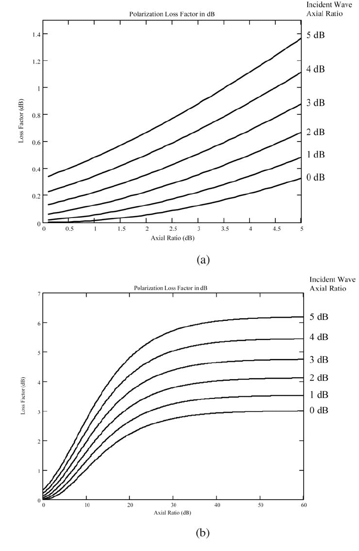
For the purpose of link budgeting, the worst-case polarization loss factor is
employed. The worst case occurs when t=90 degrees. Figure 3.12 (a) is a plot
of the polarization loss factor in dB for a tilt angle of 90 degrees, as a function
of incident axial ratio for several different antenna axial ratios. By selecting a
curve with the receive antenna axial ratio and finding the wave (transmit) axial
ratio along the x axis or vice versa, the polarization loss factor can be read
from the y axis of the plot.
In some circumstances, a circularly polarized antenna might be used to
receive a linearly polarized wave or vice versa. This may occur when an
antenna serves multiple purposes, or if the orientation of the linear polariza-
tion is unknown, then use of a circular polarized receive antenna might be con-
sidered. For instance, the orientation of a linearly polarized antenna on an
aircraft will vary with the aircraft’s attitude. In this case, using a circularly
polarized antenna at the other end of the communication link would elimi-
nate the variability in signal strength at the expense of taking a constant loss
in signal strength of about 3 dB. The polarization loss factor between linear
and circular polarization is generally assumed to result in a 3-dB polarization
loss factor, regardless of the orientation of the linearly polarized wave.
However, if the circularly polarized antenna is not ideal (i.e., axial ratio greater
than 1), then the actual polarization loss factor is a function of the tilt angle.
F
AR AR AR AR AR AR
AR AR
wrwr wrwr
wr
=
+
()
+
()
++-
()
-
()
-
[]
()
+
()
+
()
11 4 11
21 1
22 22
22
cos 2 tt
F
k
AR
k
AR
wr
wr
=
Ê
Ë
ˆ
¯
-
Ê
Ë
ˆ
¯
Ê
Ë
ˆ
¯
-
[]
()
È
Î
Í
˘
˚
˙
Ï
Ì
Ó
¸
˝
˛
---
cos tan cos cos 2tan cos 2
21 1 1
1
2
tt
60 ANTENNA FUNDAMENTALS
ANTENNA POLARIZATION 61
Figure 3.12 Worst-case polarization loss factor versus axial ratio for CP.