Thomas M. Cover, Joy A. Thomas. Elements of information theory
Подождите немного. Документ загружается.

15.3 MULTIPLE-ACCESS CHANNEL 545
Now, we can expand the mutual information in terms of relative
entropy, and thus
I(X
1
;Y |X
2
) = h(Y |X
2
) − h(Y |X
1
,X
2
) (15.138)
= h(X
1
+ X
2
+ Z|X
2
) − h(X
1
+ X
2
+ Z|X
1
,X
2
)
(15.139)
= h(X
1
+ Z|X
2
) − h(Z|X
1
,X
2
) (15.140)
= h(X
1
+ Z|X
2
) − h(Z) (15.141)
= h(X
1
+ Z) − h(Z) (15.142)
= h(X
1
+ Z) −
1
2
log(2πe)N (15.143)
≤
1
2
log(2πe)(P
1
+ N) −
1
2
log(2πe)N (15.144)
=
1
2
log
1 +
P
1
N
, (15.145)
where (15.141) follows from the fact that Z is independent of X
1
and
X
2
, (15.142) from the independence of X
1
and X
2
, and (15.144) from
the fact that the normal maximizes entropy for a given second moment.
Thus, the maximizing distribution is X
1
∼ N(0,P
1
) and X
2
∼ N(0,P
2
)
with X
1
and X
2
independent. This distribution simultaneously maximizes
the mutual information bounds in (15.135)–(15.137).
Definition We define the channel capacity function
C(x)
=
1
2
log(1 + x), (15.146)
corresponding to the channel capacity of a Gaussian white-noise channel
with signal-to-noise ratio x (Figure 15.17). Then we write the bound on
R
1
as
R
1
≤ C
P
1
N
. (15.147)
Similarly,
R
2
≤ C
P
2
N
(15.148)
546 NETWORK INFORMATION THEORY
R
2
R
1
D
P
2
N
C
C
B
A
0
P
1
N
C
P
2
P
1
+
N
C
P
1
P
2
+
N
C
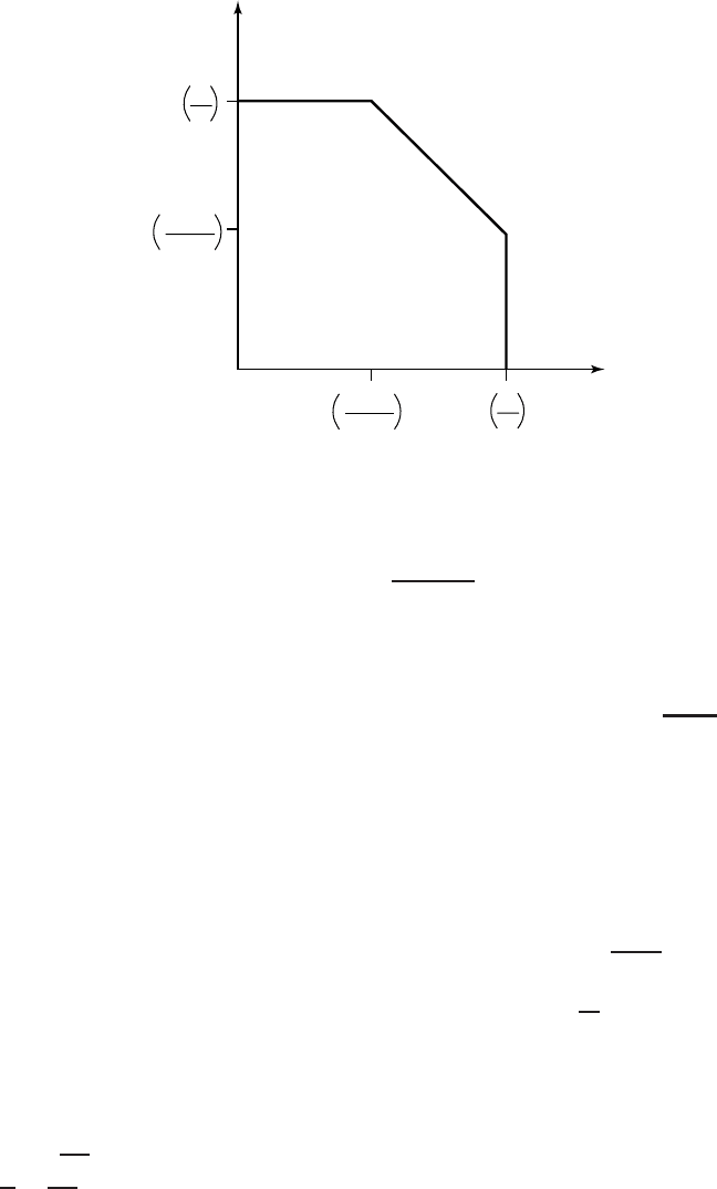
FIGURE 15.17. Gaussian multiple-access channel capacity.
and
R
1
+ R
2
≤ C
P
1
+ P
2
N
. (15.149)
These upper bounds are achieved when X
1
∼ N(0,P
1
) and X
2
=
N(0,P
2
) and define the capacity region. The surprising fact about these
inequalities is that the sum of the rates can be as large as C
P
1
+P
2
N
,
which is that rate achieved by a single transmitter sending with a power
equal to the sum of the powers.
The interpretation of the corner points is very similar to the interpre-
tation of the achievable rate pairs for a discrete multiple-access channel
for a fixed input distribution. In the case of the Gaussian channel, we can
consider decoding as a two-stage process: In the first stage, the receiver
decodes the second sender, considering the first sender as part of the noise.
This decoding will have low probability of error if R
2
<C(
P
2
P
1
+N
).After
the second sender has been decoded successfully, it can be subtracted out
and the first sender can be decoded correctly if R
1
<C(
P
1
N
). Hence, this
argument shows that we can achieve the rate pairs at the corner points
of the capacity region by means of single-user operations. This process,
called onion-peeling, can be extended to any number of users.
If we generalize this to m senders with equal power, the total rate
is C
mP
N
, which goes to ∞ as m →∞. The average rate per sender,
1
m
C(
mP
N
), goes to 0. Thus, when the total number of senders is very large,
15.3 MULTIPLE-ACCESS CHANNEL 547
so that there is a lot of interference, we can still send a total amount of
information that is arbitrarily large even though the rate per individual
sender goes to 0.
The capacity region described above corresponds to code-division mul-
tiple access (CDMA), where separate codes are used for the different
senders and the receiver decodes them one by one. In many practical situ-
ations, though, simpler schemes, such as frequency-division multiplexing
or time-division multiplexing, are used. With frequency-division multiplex-
ing, the rates depend on the bandwidth allotted to each sender. Consider
the case of two senders with powers P
1
and P
2
using nonintersecting
frequency bands with bandwidths W
1
and W
2
,whereW
1
+ W
2
= W (the
total bandwidth). Using the formula for the capacity of a single-user ban-
dlimited channel, the following rate pair is achievable:
R
1
= W
1
log
1 +
P
1
NW
1
, (15.150)
R
2
= W
2
log
1 +
P
2
NW
2
. (15.151)
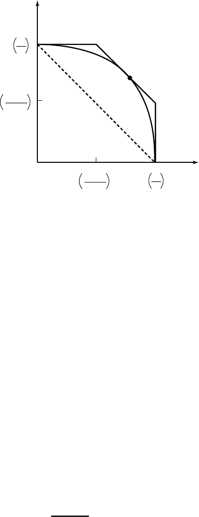
As we vary W
1
and W
2
, we trace out the curve as shown in Figure 15.18.
This curve touches the boundary of the capacity region at one point,
which corresponds to allotting bandwidth to each channel proportional to
the power in that channel. We conclude that no allocation of frequency
bands to radio stations can be optimal unless the allocated powers are
proportional to the bandwidths.
In time-division multiple access (TDMA), time is divided into slots,
and each user is allotted a slot during which only that user will transmit
and every other user remains quiet. If there are two users, each of power
P , the rate that each sends when the other is silent is C(P/N).Nowif
time is divided into equal-length slots, and every odd slot is allocated
to user 1 and every even slot to user 2, the average rate that each user
achieves is
1
2
C(P/N). This system is called naive time-division multiple
access (TDMA). However, it is possible to do better if we notice that since
user 1 is sending only half the time, it is possible for him to use twice
the power during his transmissions and still maintain the same average
power constraint. With this modification, it is possible for each user to
send information at a rate
1
2
C(2P/N). By varying the lengths of the
slots allotted to each sender (and the instantaneous power used during the
slot), we can achieve the same capacity region as FDMA with different
bandwidth allocations.
As Figure 15.18 illustrates, in general the capacity region is larger than
that achieved by time- or frequency-division multiplexing. But note that
548 NETWORK INFORMATION THEORY
R
2
R
1
P
2
N
C
0
P
1
N
C
P
2
P
1
+
N
C
P
1
P
2
+
N
C
FIGURE 15.18. Gaussian multiple-access channel capacity with FDMA and TDMA.
the multiple-access capacity region derived above is achieved by use of
a common decoder for all the senders. However, it is also possible to
achieve the capacity region by onion-peeling, which removes the need
for a common decoder and instead, uses a sequence of single-user codes.
CDMA achieves the entire capacity region, and in addition, allows new
users to be added easily without changing the codes of the current users.
On the other hand, TDMA and FDMA systems are usually designed for
a fixed number of users and it is possible that either some slots are empty
(if the actual number of users is less than the number of slots) or some
users are left out (if the number of users is greater than the number
of slots). However, in many practical systems, simplicity of design is
an important consideration, and the improvement in capacity due to the
multiple-access ideas presented earlier may not be sufficient to warrant
the increased complexity.
For a Gaussian multiple-access system with m sources with powers
P
1
,P
2
,...,P
m
and ambient noise of power N , we can state the equivalent
of Gauss’s law for any set S in the form
i∈S
R
i
= total rate of information flow from S (15.152)
≤ C
i∈S
P
i
N
. (15.153)

15.4 ENCODING OF CORRELATED SOURCES 549
15.4 ENCODING OF CORRELATED SOURCES
We now turn to distributed data compression. This problem is in many
ways the data compression dual to the multiple-access channel problem.
We know how to encode a source X.ArateR>H(X)is sufficient. Now
suppose that there are two sources (X, Y ) ∼ p(x, y).ArateH(X,Y)
is sufficient if we are encoding them together. But what if the X and
Y sources must be described separately for some user who wishes to
reconstruct both X and Y ? Clearly, by separately encoding X and Y ,itis
seen that a rate R = R
x
+ R
y
>H(X)+ H(Y) is sufficient. However, in
a surprising and fundamental paper by Slepian and Wolf [502], it is shown
that a total rate R = H(X,Y) is sufficient even for separate encoding of
correlated sources.
Let (X
1
,Y
1
), (X
2
,Y
2
), . . . be a sequence of jointly distributed random
variables i.i.d. ∼ p(x, y). Assume that the X sequence is available at a
location A and the Y sequence is available at a location B. The situation
is illustrated in Figure 15.19.
Before we proceed to the proof of this result, we will give a few
definitions.
Definition A ((2
nR
1
, 2
nR
2
), n) distributed source code for the joint
source (X, Y ) consists of two encoder maps,
f
1
: X
n
→{1, 2,...,2
nR
1
}, (15.154)
f
2
: Y
n
→{1, 2,...,2
nR
2
}, (15.155)
X
(
X
,
Y
)
(
X
,
Y
)
Encoder
Decoder
R
1
Y
Encoder
R
2
^^
FIGURE 15.19. Slepian–Wolf coding.

550 NETWORK INFORMATION THEORY
and a decoder map,
g : {1, 2,...,2
nR
1
}×{1, 2,...,2
nR
2
}→X
n
× Y
n
. (15.156)
Here f
1
(X
n
) is the index corresponding to X
n
, f
2
(Y
n
) is the index cor-
responding to Y
n
,and(R
1
,R
2
) is the rate pair of the code.
Definition The probability of error for a distributed source code is
defined as
P
(n)
e
= P(g(f
1
(X
n
), f
2
(Y
n
)) = (X
n
,Y
n
)). (15.157)
Definition A rate pair (R
1
,R
2
) is said to be achievable for a distributed
source if there exists a sequence of ((2
nR
1
, 2
nR
2
), n) distributed source
codes with probability of error P
(n)
e
→ 0. The achievable rate region is
the closure of the set of achievable rates.
Theorem 15.4.1 (Slepian–Wolf ) For the distributed source coding
problem for the source (X, Y ) drawn i.i.d ∼ p(x, y), the achievable rate
region is given by
R
1
≥ H(X|Y), (15.158)
R
2
≥ H(Y|X), (15.159)
R
1
+ R
2
≥ H(X,Y). (15.160)
Let us illustrate the result with some examples.
Example 15.4.1 Consider the weather in Gotham and Metropolis. For
the purposes of our example, we assume that Gotham is sunny with prob-
ability 0.5 and that the weather in Metropolis is the same as in Gotham
with probability 0.89. The joint distribution of the weather is given as
follows:
Metropolis
p(x, y) Rain Shine
Gotham
Rain 0.445 0.055
Shine
0.055 0.445
15.4 ENCODING OF CORRELATED SOURCES 551
Assume that we wish to transmit 100 days of weather information to the
National Weather Service headquarters in Washington. We could send all
the 100 bits of the weather in both places, making 200 bits in all. If we
decided to compress the information independently, we would still need
100H(0.5) = 100 bits of information from each place, for a total of 200
bits. If, instead, we use Slepian–Wolf encoding, we need only H(X)+
H(Y|X) = 100H(0.5) + 100H(0.89) = 100 + 50 = 150 bits total.
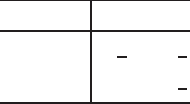
Example 15.4.2 Consider the following joint distribution:
p(u, v) 01
0
1
3
1
3
1 0
1
3
In this case, the total rate required for the transmission of this
source is H(U)+ H(V|U) = log 3 = 1.58 bits rather than the 2 bits that
would be needed if the sources were transmitted independently without
Slepian–Wolf encoding.
15.4.1 Achievability of the Slepian–Wolf Theorem
We now prove the achievability of the rates in the Slepian–Wolf theorem.
Before we proceed to the proof, we introduce a new coding procedure
using random bins. The essential idea of random bins is very similar to
hash functions: We choose a large random index for each source sequence.
If the set of typical source sequences is small enough (or equivalently, the
range of the hash function is large enough), then with high probability,
different source sequences have different indices, and we can recover the
source sequence from the index.
Let us consider the application of this idea to the encoding of a single
source. In Chapter 3 the method that we considered was to index all
elements of the typical set and not bother about elements outside the
typical set. We will now describe the random binning procedure, which
indexes all sequences but rejects untypical sequences at a later stage.
Consider the following procedure: For each sequence X
n
, draw an index
at random from {1, 2,...,2
nR
}. The set of sequences X
n
which have the
same index are said to form a bin, since this can be viewed as first laying
down a row of bins and then throwing the X
n
’s at random into the bins.
For decoding the source from the bin index, we look for a typical X
n
sequence in the bin. If there is one and only one typical X
n
sequence
in the bin, we declare it to be the estimate
ˆ
X
n
of the source sequence;
otherwise, an error is declared.
552 NETWORK INFORMATION THEORY
The above procedure defines a source code. To analyze the probability
of error for this code, we will now divide the X
n
sequences into two
types, typical sequences and nontypical sequences. If the source sequence
is typical, the bin corresponding to this source sequence will contain at
least one typical sequence (the source sequence itself). Hence there will
be an error only if there is more than one typical sequence in this bin. If
the source sequence is nontypical, there will always be an error. But if
the number of bins is much larger than the number of typical sequences,
the probability that there is more than one typical sequence in a bin is
very small, and hence the probability that a typical sequence will result
in an error is very small.
Formally, let f(X
n
) be the bin index corresponding to X
n
.Callthe
decoding function g. The probability of error (averaged over the random
choice ofcodes f )is
P(g(f(X)) = X) ≤ P(X /∈ A
(n)
) +
x
P(∃x
= x : x
∈ A
(n)
,f(x
)
= f(x))p(x)
≤ +
x
x
∈ A
(n)
x
= x
P(f(x
) = f(x))p(x) (15.161)
≤ +
x
x
∈A
(n)
2
−nR
p(x) (15.162)
= +
x
∈A
(n)
2
−nR
x
p(x) (15.163)
≤ +
x
∈A
(n)
2
−nR
(15.164)
≤ + 2
n(H (X)+)
2
−nR
(15.165)
≤ 2 (15.166)
if R>H(X)+ and n is sufficiently large. Hence, if the rate of the code
is greater than the entropy, the probability of error is arbitrarily small and
the code achieves the same results as the code described in Chapter 3.
The above example illustrates the fact that there are many ways to
construct codes with low probabilities of error at rates above the entropy
of the source; the universal source code is another example of such a code.
15.4 ENCODING OF CORRELATED SOURCES 553
Note that the binning scheme does not require an explicit characterization
of the typical set at the encoder; it is needed only at the decoder. It is
this property that enables this code to continue to work in the case of a
distributed source, as illustrated in the proof of the theorem.
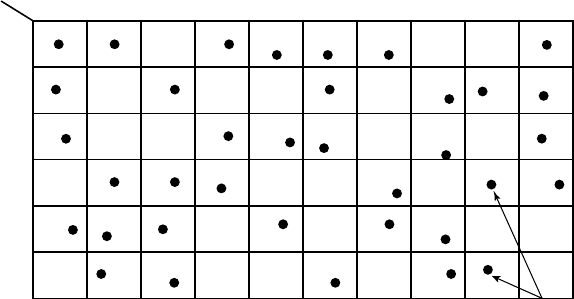
We now return to the consideration of the distributed source coding and
prove the achievability of the rate region in the Slepian–Wolf theorem.
Proof: (Achievability in Theorem 15.4.1). The basic idea of the proof is
to partition the space of
X
n
into 2
nR
1
bins and the space of Y
n
into 2
nR
2
bins.
Random code generation: Assign every x ∈
X
n
to one of 2
nR
1
bins
independently according to a uniform distribution on {1, 2,...,2
nR
1
}.
Similarly, randomly assign every y ∈
Y
n
to one of 2
nR
2
bins. Reveal
the assignments f
1
and f
2
to both the encoder and the decoder.
Encoding: Sender 1 sends the index of the bin to which X belongs.
Sender 2 sends the index of the bin to which Y belongs.
Decoding: Given the received index pair (i
0
,j
0
), declare (
ˆ
x,
ˆ
y) = (x, y)
if there is one and only one pair of sequences (x, y) such that f
1
(x) = i
0
,
f
2
(y) = j
0
and (x, y) ∈ A
(n)
. Otherwise, declare an error. The scheme
is illustrated in Figure 15.20. The set of X sequences and the set of Y
sequences are divided into bins in such a way that the pair of indices
specifies a product bin.
2
nH
(
X
,
Y
)
jointly typical pairs
(
x
n
,
y
n
)
2
nR
1
bins
y
n
x
n
2
nR
2
bins
FIGURE 15.20. Slepian–Wolf encoding: the jointly typical pairs are isolated by the product
bins.
554 NETWORK INFORMATION THEORY
Probability of error:Let(X
i
,Y
i
) ∼ p(x, y). Define the events
E
0
={(X, Y )/∈ A
(n)
}, (15.167)
E
1
={∃x
= X : f
1
(x
) = f
1
(X) and (x
, Y) ∈ A
(n)
}, (15.168)
E
2
={∃y
= Y : f
2
(y
) = f
2
(Y) and (X, y
) ∈ A
(n)
}, (15.169)
and
E
12
={∃(x
, y
) : x
= X, y
= Y,f
1
(x
)
= f
1
(X), f
2
(y
) = f
2
(Y) and (x
, y
) ∈ A
(n)
}. (15.170)
Here X, Y,f
1
,andf
2
are random. We have an error if (X, Y) is not in
A
(n)
or if there is another typical pair in the same bin. Hence by the union
of events bound,
P
(n)
e
= P(E
0
∪ E
1
∪ E
2
∪ E
12
) (15.171)
≤ P(E
0
) + P(E
1
) + P(E
2
) + P(E
12
). (15.172)
First consider E
0
. By the AEP, P(E
0
) → 0 and hence for n sufficiently
large, P(E
0
)<. To bound P(E
1
),wehave
P(E
1
) = P {∃x
= X : f
1
(x
) = f
1
(X), and (x
, Y) ∈ A
(n)
} (15.173)
=
(x,y)
p(x, y)P {∃x
= x : f
1
(x
) = f
1
(x), (x
, y) ∈ A
(n)
}
(15.174)
≤
(x,y)
p(x, y)
x
= x
(x
, y) ∈ A
(n)
P(f
1
(x
) = f
1
(x)) (15.175)
=
(x,y)
p(x, y)2
−nR
1
|A
(X|y)| (15.176)
≤ 2
−nR
1
2
n(H (X|Y)+)
(by Theorem 15.2.2 ), (15.177)
which goes to 0 if R
1
>H(X|Y). Hence for sufficiently large n, P(E
1
)<
. Similarly, for sufficiently large n, P(E
2
)< if R
2
>H(Y|X) and
P(E
12
)<if R
1
+ R
2
>H(X,Y). Since the average probability of error
is < 4, there exists at least one code (f
∗
1
,f
∗
2
,g
∗
) with probability of error
< 4. Thus, we can construct a sequence of codes with P
(n)
e
→ 0, and
the proof of achievability is complete.