Tsoulos George (ред.) MIMO System Technology for Wireless Communications
Подождите немного. Документ загружается.

4 MIMO System Technology for Wireless Communications
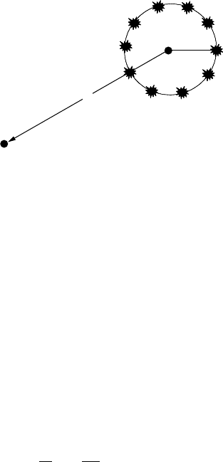
1.2.1 Ring of Scatterers [6]
In this model, the effective scatterers (each effective scatterer comprises a
cluster of scatterers) are uniformly spaced on a circular ring around the
mobile (Figure 1.2). In the one-ring-of-scatterers models, the BS is assumed
to be elevated and therefore not obstructed by local scattering, while the MS
is surrounded by scatterers and no Line-of-Sight (LOS) is assumed between
BS and MS.
Based on Figure 1.2 and assuming that N
scatterers are uniformly placed
on a circle with radius R around the mobile at distance D
from the base
station, the discrete angle of arrivals is [7]:
The model was originally used to predict signal correlation as a function
of antenna element spacing. Although correlation measurements at the BS
and MS are consistent with a narrow/wide angular spread at the BS/MS,
respectively, the power delay profile predicted by this model is not generally
consistent with measurements. As a result there have been proposals (e.g.,
[8]) where additional rings of scatterers are added in an attempt to rectify
this problem. Furthermore, because small scale fading requires consideration
of Doppler shift, [8, 9] have proposed extensions that take into account this
effect.
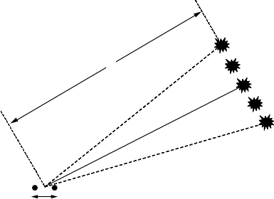
1.2.2 Discrete Uniform Distribution Model [10]
This is a model similar to Lee’s ring of scatterers model [6]. Figure 1.3 shows
that it considers scatterers evenly located within a narrow beamwidth cen-
tered around the direction of the mobile.
FIGURE 1.2
One-ring-of-scatterers model.
MS
R
BS
D
D
V
U
i
R
DN
ii N=
©
«
ª
¹
»
º
=sin , , ,
2
1
4190_book.fm Page 4 Tuesday, February 21, 2006 9:14 AM
Spatio-Temporal Propagation Modeling
5
Analysis performed by the same author suggests that, due to the fact that
in practice the AoA is discrete, a continuous AoA distribution (reported as
Gaussian for rural-suburban environments) will underestimate the correla-
tion that exists between the antenna array elements.
1.2.3 Geometrically Based Single-Bounce (GBSB) Statistical
Channel Models
This kind of model assumes that scatterers are placed in a region according
to a spatial scatterer density function. From the location of each scatterer,
the AoA, Time-of-Arrival (ToA), and signal amplitude can be determined
along with the relevant probability density functions. In order to make the
calculations easier, two important assumptions are usually made.
First, the signal undergoes only one reflection when it travels from the MS
to the BS. Then, all scatterers confined within the scattering area are isotropic
re-radiating elements, with random complex scattering coefficients (yet, in
practice it is rather difficult to assign realistic scattering coefficients).
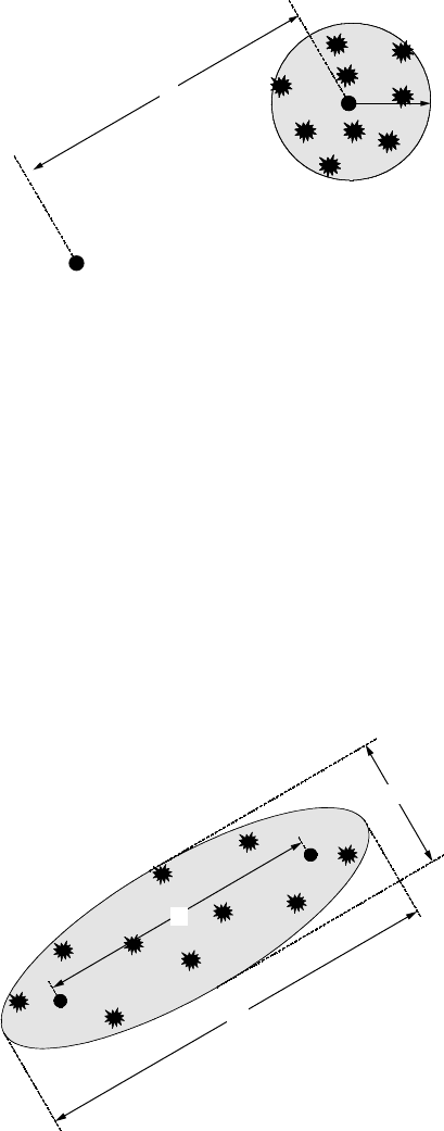
1.2.3.1 Geometrically Based Circular Model (Macrocell Model)
The idea behind this model [11–13] is shown in Figure 1.4. It assumes that
the scatterers lie within radius R
m
about the mobile. The joint ToA and AoA
pdfs are reported in [2], where it is also shown that the circular model
predicts a relatively high probability of multipath components with small
excess delay along the line of sight, i.e., the model is more suitable for large
cell environments, where all the multipath components lie within a small
angular spread. The appropriate values for the radius of the scattering
depend on the macrocellular type of environment (urban, dense urban, etc.)
and the model can be “tuned” based on results from measurements.
FIGURE 1.3
Discrete uniform distribution of scatterers.
BS
d
D
4190_book.fm Page 5 Tuesday, February 21, 2006 9:14 AM
6 MIMO System Technology for Wireless Communications
1.2.3.2 Geometrically Based Elliptical Model (Microcell Model)
Figure 1.5 shows that this model places the base station and the mobile at
the foci of an ellipse and distributes the scatterers uniformly within the ellipse.
It was proposed in [14] for applications in microcellular environments, since
in such environments antenna heights are relatively low, and hence, multi-
path scattering near the base station and the mobile is just as likely. The
semi-major and semi-minor axes are calculated as a function of the maximum
ToA to be considered, and this determines both the delay spread and angular
spread of the channel.
According to [15], this model produces a high probability of scatterers with
minimum excess delay along the LOS.
FIGURE 1.4
Geometrically based circular model.
FIGURE 1.5
Geometrically based elliptical model.
BS
MS
R
D
D
BS
MS
2a
2b
D
4190_book.fm Page 6 Tuesday, February 21, 2006 9:14 AM
Spatio-Temporal Propagation Modeling
7
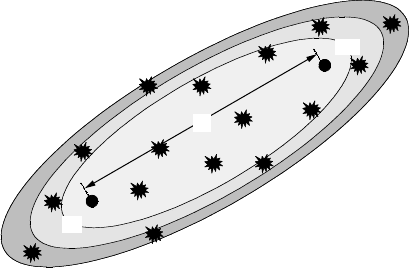
1.2.3.3 Elliptical Subregions Model [16]
If the distribution of scatterers in elliptical subregions (corresponding to
different ranges of excess delay) is considered, then we get the model shown
in Figure 1.6.
This approach is similar to the Geometrical Based Elliptical Model pro-
posed by [14], where the scatterers are uniformly distributed within the
entire ellipse, while here the ellipse is subdivided into a number of elliptical
subregions. A number of scatterers is then selected within each subregion
employing a Poisson random variable, with its mean chosen to match the
measured time characteristics. Furthermore, due to multiple reflection points
of the scatterers, the multipath components arrive in clusters.
1.2.3.4 Elliptical Model with Dense Discrete Scatterers [17]
This is a wide-band spatial model, where diffuse scattering is modeled using
dense discrete scatterers. The transmitter and receiver define the focal points
of ellipses with constant propagation delay. The scatterers are distributed on
ellipsoids. To simplify the model, only the intersection of the ellipsoid and
the ground is used. A uniform distribution of scatterers is assumed, although
the calculated distribution function for the scatterers around the mobile is
not uniform (it has two spikes). Two channel models are defined — a rural
macrocell model and an urban microcell model.
1.2.4 Gaussian Wide Sense Stationary Uncorrelated
Scattering (GWSSUS)
This is a statistical model that makes assumptions about the received signal
vector [18–20] (Figure 1.7). Although scatterers are grouped in clusters, spatio-
temporal multipath is not resolvable within a cluster, i.e., the narrowband
channel assumption is satisfied. Nevertheless, frequency-selective fading
channels can be modeled by including multiple clusters.
FIGURE 1.6
Elliptical subregions model.
B S
M S
BS
MS
DD
4190_book.fm Page 7 Tuesday, February 21, 2006 9:14 AM
8 MIMO System Technology for Wireless Communications
The steering vector(s
), due to multipaths from the k
th
cluster, can be
expressed in this case as the sum of all the contributions (K
) from the scat-
terers within the k
th
cluster:
where F
i,k
is the amplitude, ^
i,k
the phase and O
i,k
the relative AoA of the i
th
multipath in the k
th
cluster, and a
(O
) is the complex array response vector of
the receive antenna elements for direction and operating frequency f.
If the number of scatterers in each O
cluster is sufficiently large, (v
10 from
[18]), then this sum is Gaussian distributed (central limit theorem). Also,
wide sense stationarity is assumed, which leads to the steering vector being
multi-variate Gaussian distributed and, hence, described by its mean and
covariance matrix, presented in [19].
A special case of the GWSSUS model is the Gaussian AoA model [21],
where only one cluster is considered and the AoA statistics are assumed to
be Gaussian distributed about the direction of the cluster (narrowband flat
fading model).
1.2.5 A Stochastic Spatio-Temporal Propagation Model (SSTPM)
The GWSSUS channel model does not impose any conditions on the spatial
distribution of the received power, hence, requiring additional information
in order to be used in space–time studies. The GBSB channel models, on the
other hand, do not provide information about the temporal evolution of the
generated channel characteristics, resulting in consecutive snapshots being
un-correlated, an un-realistic assumption.
In order to avoid these problems, [22] and [23] proposed a hybrid
approach, which combined these two classes of channel models (the GBSB
FIGURE 1.7
The GWSSUS model.
BS
MS
Scatterer clusters
sa
kik ikik
i
K
j=
()()
=
¨
F^O
,,,
exp
1
4190_book.fm Page 8 Tuesday, February 21, 2006 9:14 AM
Spatio-Temporal Propagation Modeling
9
and GWSSUS) and further considered time variations associated with the
movement of the mobile (non-stationary scenarios), as shown in Figure 1.8.
The scattering area in the presented model has a circular shape (although
the general elliptical case can also be considered), and a uniform distribution
of scatterers is assumed (given area density of scatterers, which depends on
the type of environment, i.e., urban, suburban, rural). As shown in Figure 1.8,
the mobile is located at the center of the circular scattering area, which moves
together with the mobile. The scatterers are positioned at fixed locations
throughout a large area (e.g., the cell), but active scatterers are only those
within the circular scattering area. As a result, the number of multipaths is
not fixed as the mobile moves but follows a random process (Poisson dis-
tributed). The expected number of scatterers depends on the scatterers’ area
density and the scattering area size, and hence, it depends on the type of
the operational environment. The pdf of the “scatterers’ lifetime” is also
calculated from the authors, and is shown to depend on the size of the
scattering area and the mobile speed.
The angular spread of the channel is described by the probability density
function (pdf) of the angle of arrival and was derived in [24]:
where F =R/l
BM
, i.e., the cluster radius over the distance between the MS and
the BS. The above expression is a special case of the formula derived in [24]
for the elliptical case:
FIGURE 1.8
Stochastic spatio-temporal propagation model concept.
BS
R
MS’
MS
R
f
F
k
kk kk
O
O
U
OO OOO
()
=
() ()
+ <<
2
1
22
cos cos
max
for
kk max
0 elsewhere
¯
°
²
²
±
²
²
4190_book.fm Page 9 Tuesday, February 21, 2006 9:14 AM

10 MIMO System Technology for Wireless Communications
where a, b, d
are the major and minor axes of the ellipse and the distance
from the BS, respectively, F = a/d
and E = b/a
, and <
can be calculated from
As mentioned above, the consecutive channel characteristics have corre-
lated temporal characteristics, hence allowing for the direct calculation of
the correlation functions.
1.2.6 Extended Saleh-Valenzuela Model
In [25] extensive indoor measurements using a system that collects simulta-
neous time and angle of arrival data at 7 GHz have shown a clustering
pattern in the time-angle multipath data. The model proposed for indoor
environments employs the clustered “double Poisson” time-of-arrival model
proposed by Saleh and Valenzuela [26], with statistical independence
between time and angle. The mean angles of each cluster are distributed
uniformly over all angles. The distribution of arrivals within clusters is
approximately Laplacian, with standard deviations ranging from 22° to 26°.
1.2.7 Gaussian Scatter Density Model
The spatial characteristics of the radio channel are studied in [27], based on
work presented in [28], with the Gaussian Scatter Density Model (GSDM).
Starting from a Gaussian distribution of scatterers around a mobile station,
expressions are provided for the pdfs of AoA, the power azimuth spectrum,
the ToA, and the time delay spread, all as seen from a BS. Expressions are
also provided for the rms delay spread, the rms angular spread and the
spatial cross correlation function.
Also, with an appropriate choice of the standard deviation of the scattering
region, the Gaussian density model is suitable for environments with small
angular spreads (macrocells) or with large angular spreads (picocells). When
f
E
O
O
OO O O
()
=
() ()
()
+
cos cos cos sin
1
2222
<
(()
()
()
()
+
()
()
<<
1
2
22 2
2
F
E cos sin
max
OO
OOOfor
mmax
0elsewhere
¯
°°
²
²
²
±
²
²
²
fd
O
O
O
OO
()
=
µ
1
max
max
4190_book.fm Page 10 Tuesday, February 21, 2006 9:14 AM
Spatio-Temporal Propagation Modeling
11
the scattering width is small compared with the distance between the BS
and the MS, it is shown that the pdf in the AoA reduces to the Gaussian
function.
1.2.8 Gaussian AoA — Laplacian Power Azimuth Spectrum
A statistical model of azimuthal and temporal dispersion in mobile radio
channels is presented in [29]. Based on field trial results, it is proposed that
for typical urban environments, the power azimuth spectrum (PAS) can be
modeled by a Laplacian function, while the power delay spectrum (PDS)
can be modeled by a one-sided exponential decaying function.
Positive correlation between azimuth and delay spread also was observed
from the measurements. Hence, propagation environments with high angu-
lar spread also have high delay spread, and vice versa. A significant increase
in both angular and delay spread was also observed with the lowering of
the BS antenna below rooftop height.
The pdf of the azimuth of the multipath rays was found to match a
Gaussian function, while the pdf of their delays matched a one-sided expo-
nential decay function.
For bad urban environments, a two-cluster model was proposed, with the
PAS described by the sum of two Laplacian functions and the PDS by the
sum of two exponentially decaying functions. The power azimuth-delay
spectrum could not be expressed as a product of the PDS and PAS in this
case, contrary to the typical urban scenario.
1.2.9 Semi-Elliptical Geometrical Model
In [30, 31] a geometric-based channel model with a semi-elliptical coverage
area is applied in order to determine a new PAS model (called the secant
square PAS model). This model is appropriate for environments where the
BS is on a building with height close to that of the surrounding building
scatterers, and the authors show that it is a better fit to the employed exper-
imental results (from the European project TSUNAMI II) than the previously
proposed Laplacian model for these scenarios.
1.2.10 Lognormal Distribution of Local Angular Spread (AS),
Delay Spread (DS), and Shadow Fading (Macrocells)
In [32] the joint statistical behavior of the random variables describing the
local AS, the local DS, and the shadow fading component is studied using
measurements in macrocellular (including NLOS) scenarios. It is found that
a log-normal distribution provides an accurate fit of the measured pdfs for
all three parameters. Their spatial autocorrelation functions follow an expo-
nential decay for typical and bad urban environments, and a double exponen-
tial decay in suburban environments. The decorrelation distance of the AS,
4190_book.fm Page 11 Tuesday, February 21, 2006 9:14 AM
12 MIMO System Technology for Wireless Communications
DS, and shadow fading is observed to be nearly identical within each envi-
ronment class. The fact that the pdf and the spatial autocorrelation function
of the three parameters are identical indicates that the propagation mecha-
nisms leading to these effects are strongly related.
1.3 MIMO Propagation Modeling
The discussion up to now has considered single-input-multiple-output
(SIMO) propagation models. This section focuses more on the multiple-
input-multiple-output (MIMO) propagation models. Figure 1.9 shows a
MIMO system with M
transmit and N
receive antenna elements. The general
expression for the baseband signal in this case can be expressed as:
where y
(t
) is the received, s
(t
) the transmitted, n
(t
) the noise signal, * denotes
convolution, and H
(t) is the M
×
N
channel matrix. If the signal bandwidth
is narrow enough so that the channel can be considered approximately
constant over frequency, then we get the narrowband MIMO channel matrix.
Otherwise, we get the wideband MIMO channel matrix.
Based on a similar approach to that presented in the previous section, this
section addresses two major categories of models:
• Deterministic
• Stochastic (parametric, geometric, correlation)
Some of the models presented in the following sections are based on
propagation measurements ([1] and [5] include good surveys on space–time
measurement campaigns).
FIGURE 1.9
MIMO system concept.
yHsn() () () ()tttt= +
M
N
H(t)
4190_book.fm Page 12 Tuesday, February 21, 2006 9:14 AM

Spatio-Temporal Propagation Modeling
13
1.3.1 Deterministic Propagation Modeling with Ray Tracing
This modeling approach has evolved from SISO to SIMO and, more recently,
MIMO scenarios, and hence, it is discussed here, in the MIMO propagation
modeling section, since the last represents the more general approach.
Ray tracing is a technique based on Geometrical Optics
(GO
), an easily
applied approximate method for estimating a high-frequency electromagnetic
field [33]. The dissipating energy is considered to be radiating in infinitesimally
small tubes, often called rays. These rays are normal to the surface of equal
signal power, lie in the direction of propagation, and travel in straight lines,
provided that the refractive index is constant. Their amplitude is governed
by the conservation of energy flux in the ray tube. In GO, only direct, reflected
and refracted rays are considered, and consequently abrupt transition areas
occur, corresponding to the boundaries of the regions where these rays exist.
The Geometrical Theory of Diffraction (GTD) [34] and its uniform extension,
the Uniform GTD (UTD) [35, 36], complement the GO theory by introducing
a new type of rays, known as the diffracted rays. The purpose of these rays
is to remove the field discontinuities and to introduce proper field correc-
tions, especially in the zero field areas predicted by GO.
The extended Fermat principle and the principle of local field are two basic
concepts extensively used by the ray models [37]. While the original Fermat
principle states that a GO ray follows the shortest path from a source point
to a field point, the extended Fermat principle also includes the diffracted
rays and states that these rays follow the shortest path as well. The principle
of the local field states that the high frequency boundary processes, such as
reflection, refraction and diffraction, depend only on the electrical and geo-
metrical properties of the scatterer in the immediate neighborhood of the
point of interaction. The corresponding amplitude, phase and direction of a
ray following reflections, refractions and diffractions can be calculated using
a combination of Snell’s laws, UTD and Maxwell’s equations [33].
In a wireless communication system, the signal arriving at the receiving
antenna consists of several multipath components, each of which is the result
of the interaction of the transmitted waves with the surrounding environ-
ment. The application of GO and UTD to a given propagation problem
requires that the given configuration is decomposed into simple geometrical
configurations for which the reflection, transmission and diffraction coeffi-
cients can be calculated. All rays contributing significantly to the channel
characterization at the examined position must be traced, and the complex
impulse response h(t) of the radio channel is then found as the sum of these
contributions [38]. Here, the received signal is formed by N time delayed
impulses (rays), each represented by an attenuated and phase-shifted version
of the original transmitted impulse. For each ray, the model computes the
amplitude A
n
, the arrival time Y
n
and phase /
n
. According to the objects encoun-
tered by the i
th
ray, its complex received field amplitude E
i
(V/m) is given by:
EE
RT AssD
e
d
itiri
j
j
kl l
lk
jkd
ff=
e
{}
0
(,)
4190_book.fm Page 13 Tuesday, February 21, 2006 9:14 AM