Tsoulos George (ред.) MIMO System Technology for Wireless Communications
Подождите немного. Документ загружается.

14 MIMO System Technology for Wireless Communications
where E
0
represents the reference field, f
ti
and f
ri
the transmitting and receiv-
ing antenna field radiation patterns in the direction of the ray, R
j
the reflection
coefficient for the j
th
reflector, T
k
the wall transmission coefficient for the k
th
transmission, D
l
the diffraction coefficient for the l
th
diffracting wedge and
e
–jkd
the propagation phase factor due to the path length d (k = 2U/Q, with Q
the wavelength). The diffraction coefficients are also multiplied by a factor
A
l
(se,s) which finds the correct spatial attenuation of the diffracted rays, given
the 1/d dependence in the last term. An advantage of ray-tracing models
over other propagation models is the ability to incorporate antenna radiation
patterns and particularly to consider the effect of the radiation pattern on
each ray individually.
In order to trace rays that are generated and launched from the transmit-
ting antenna, two methods have been developed: the imaging technique and
the ray launching technique. The imaging technique (e.g., [39, 40]) is based on
the electromagnetic theory of images and works by generating an image
table for each BS location, considering all the various wall reflection, trans-
mission and diffraction permutations that are possible in a given area. The
image information is then stored and used to compute the channel charac-
teristics at each mobile location. In the ray launching approach (e.g., [41, 42]),
rays are sent out at various angles and their paths are traced until a certain
power threshold is reached. The number of rays considered and the distance
from the transmitter to the receiver location determined the available spatial
resolution and the accuracy of the model.
In the image-based models presented in [40] (for microcells), [43] (for
indoor) and [44, 45] (for macrocells), the geometry of each ray is examined
in three-dimensional (3D) space, and hence, both the azimuth and the ele-
vation angles of arrival at the antennas are available. Moreover, the 3D
antenna radiation patterns can be used and steered in any direction in space
so that the channel can be examined for any antenna orientation. Note that
the model works with the electromagnetic field of the rays and, hence, uses the
radiation patterns of the field components. This feature, in conjunction with
the fact that all reflections, transmissions and diffractions are computed
using 3D vector mathematics, makes the models very useful in the study of
different antenna polarizations and the examination of depolarization effects.
Since the field components can be calculated for each antenna element
separately, as explained above, the MIMO channel matrix can be generated,
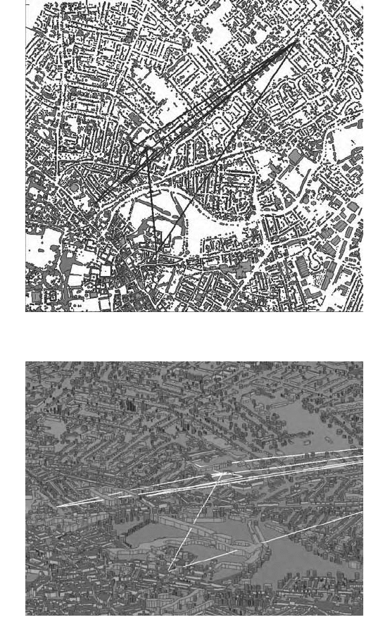
as shown in Figure 1.10 and Figure 1.11. Figure 1.10 shows the geographical
database of the area and examples of 2D-3D multipath visualization. It can
be seen that ray tracing offers site-specific information for the radio channel
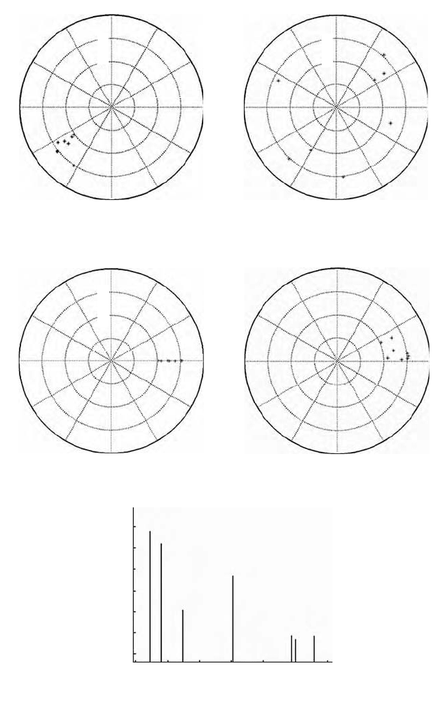
characteristics and, hence, provides more accurate predictions. Figure 1.11
shows an example of the 3D impulse responses (amplitude-delay-AoA) for
a MIMO scenario (between Tx element m and Rx element n). It shows polar
plots for the AoA (azimuth) vs. power at the BS (a) and MS (b), the AoA
(elevation) vs. power at the BS (c) and MS (d) and, finally, the ToA vs. power (e).
The application of ray-tracing models to study several aspects of propa-
gation modeling has proven to be a popular method.
4190_book.fm Page 14 Tuesday, February 21, 2006 9:14 AM
Spatio-Temporal Propagation Modeling 15
In [46, 47] the spatial characteristics of microcellular environments are stud-
ied. Results showed that the signal is not uniformly distributed in the spatial
domain, but instead is contained in a few narrow clusters. Although the number
of clusters increases under NLOS conditions, for both LOS and NLOS positions,
90% of the power is contained within two clusters. Also, although the angular
FIGURE 1.10
Map of the environment under investigation with 2D (a) and 3D (b) multipath examples.
5000
4500
4000
3500
3000
2500
500 1000 1500 2000
(a)
(
b
)
2500 3000
4190_book.fm Page 15 Tuesday, February 21, 2006 9:14 AM
16 MIMO System Technology for Wireless Communications
FIGURE 1.11
Example of ray-tracing 3D impulse responses for a MIMO scenario: AoA (azimuth) vs. power
at the BS (a) and MS (b). AoA (elevation) vs. power at the BS (c) and MS (d). (e) ToA vs. power.
90
−100
−150
120
150
180
210
240
270
(a) (b)
(c)
300
330
0
30
60
90
−100
−150
120
150
180
210
240
270
300
330
0
30
60
90
−100
−150
120
150
180
210
240
270
300
330
0
30
60
Power(dBm)
Power(dBm)
Power(dBm)
90
−100
−150
120
150
180
210
240
270
(d)
300
330
0
30
60
Power(dBm)
(e)
−100
−110
−120
−130
−140
−150
−160
Received power (dBm)
5000 6000 7000 8000
Time (nsec)
9000 10000 11000
4190_book.fm Page 16 Tuesday, February 21, 2006 9:14 AM
Spatio-Temporal Propagation Modeling 17
spread and the number of multipath rays almost doubles under NLOS condi-
tions, there are still only two important clusters that contain most of the power
with angular spread less than the beamwidth of an eight element array.
In [48] the spatial and temporal characteristics of 60GHz indoor channels
were analyzed. Multipath components were resolved in time by using a
sliding correlator with 10 ns resolution and in space by sweeping a direc-
tional antenna with 7° half power beamwidth in the azimuthal direction.
Power delay profiles (PDPs) and power angle profiles (PAPs) were measured
in various indoor and short-range outdoor environments. The measurement
results confirm that the majority of the multipath components can be deter-
mined from image-based, ray-tracing techniques for LOS applications. For
non-LOS propagation through walls, the metallic structure of composite
walls must be considered. Also, statistical parameters of received power,
AoA and ToA, were calculated from the measurements, which agreed well
with the theoretical expectations.
Furthermore, ray-tracing models have also been used to produce the data
sets required for the statistical evaluation of the parameters of stochastic mod-
els, as in [49]. The advantage of using deterministic predictions instead of field
trial measurements is mainly that large data sets can be easily produced for
many different test environments. Also, when using field trial results in order
to produce a statistical model, the influence of the measurement antennas is
included in the results and cannot be eliminated afterward. In [49], a stochastic
model for the indoor mobile propagation channel is presented. The channel
is described by multipath components, including 3D angles of arrival at the
antennas. By relating the angle of arrival to the direct line between transmitter
and receiver, a universal modeling approach, which is independent of the
actual geometry, becomes possible. In each modeling step, path properties
change according to the movement of the radio stations. The appearance and
disappearance of multipath components are modeled by a genetic process.
1.3.2 Stochastic Propagation Modeling
There have been several such models proposed, analyzed and discussed the
last few years; some of the most representative are briefly mentioned here:
• Wideband Directional Channel Model (WDCM), [50]. Geometrically
based, parameterized for macro, microcells, circular-elliptical scat-
tering area, single bounce.
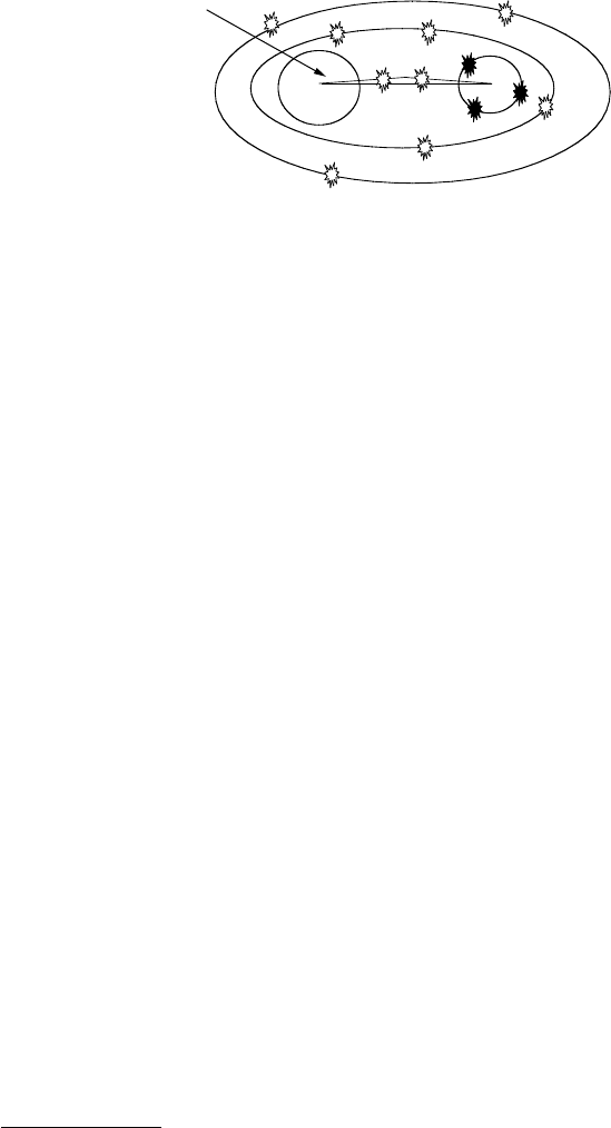
• Geometrical MIMO channel model based on SISO parameters [51, 52].
Macrocellular broadband fixed wireless, multiple delay ellipses, circle
of local scatterers around the MS, double bounces. To better repre-
sent such environments, two local rings are introduced in this model:
a disc of exclusion, representing a scatterer-free area around the BS,
and a smaller circular ring surrounding the CPE including a subset
of the scatterers in the first ellipse (see Figure 1.12). The channel
matrix is then calculated using a ray-based approach.
4190_book.fm Page 17 Tuesday, February 21, 2006 9:14 AM
18 MIMO System Technology for Wireless Communications
• Generic MIMO model [53]. Double scattering, far clusters, wave-
guiding, guidelines to select the proper distribution of scatterers.
• Double Directional Channel Model (DDCM) [54, 55]. Parametric
stochastic model, parameters through spatial scatterer distribution
[1]. Tapped delay line with each multipath having complex charac-
teristics (amplitude, delay, AoA).
• Indoor MIMO models:
– EU IST METRA (Multi-Element Transmit Receive Antennas)
project: A stochastic MIMO radio channel model for non-line-of-
sight (NLOS) scenarios was proposed on the basis of the power
correlation matrix of the MIMO radio channel [56].
– EU IST SATURN (Smart Antenna Technology in Universal Broad-
band Wireless Networks) project: Based on the statistical charac-
teristics of the measured data, both narrowband [57] and wideband
[58] statistical models for NLOS MIMO propagation channels
were developed.
• One (two) ring(s) MIMO channel models [59, 60]. Extension of [6]
for MIMO channel modeling.
• One ring MIMO model with Von Mises angular distribution [61].
Von Mises angular pdf at the MS.
• Distributed scattering MIMO model [62]. Outdoor, narrowband, one
group of scatterers near the BS and one near the MS.
1.3.2.1 The 3GPP MIMO Channel Model [63]*
A serious attempt to unify the propagation modeling approach for space–
time models started a few years ago with the European Scientific Action
COST259 [1]. This work received even more attention when adopted as the
basis for spatial channel modeling in the context of the international stan-
dardization body of 3GPP. Naturally, it was influenced by many different
FIGURE 1.12
Physical combined model for macrocellular scenarios.
* 3GPP TSs and TRs are the property of ARIB, ATIS, ETSI, CCSA, TTA, and TTC who jointly own
the copyright in them. They are subject to further modifications and are therefore provided to
you "as is" for information purposes only. Further use is strictly prohibited.
BTS
CPE
Scatterer
free area
4190_book.fm Page 18 Tuesday, February 21, 2006 9:14 AM
Spatio-Temporal Propagation Modeling 19
proposals discussed in 3GPP (see technical documents for spatial channel
model). This section describes in greater detail the parametric stochastic
model that has been adopted recently by the 3GPP.
The combined 3GPP-3GPP2 spatial channel model ad-hoc group has spec-
ified parameters and methods for spatial channel modeling. The scope is the
development of specifications for system-level evaluation with emphasis on
the physical parameters, and link-level evaluation, defined only for calibra-
tion purposes (not for evaluation or comparisons).
As such, the following section presents the key characteristics of the spatial
channel model that has been adopted for system-level simulation studies.
(A detailed description is available in [63].)
1.3.2.1.1 Spatial Channel Model for Simulations
For an S element BS array and a U element MS array, the channel coefficients
for one of N multipath components (note that these components are not
necessarily resolvable in the time domain, since the time difference between
successive paths may be less than a chip period) are given by an S-by-U
matrix of complex amplitudes. The channel matrix for the nth multipath
component (n = 1, …, N), H
n
(t), is a function of time, because the complex
amplitude undergoes fast fading due to the movement of the MS.
The overall procedure for generating the channel matrices consists of three
basic steps:
1. Specify an environment (either macro urban or macro suburban, or
micro).
2. Obtain the simulation parameters associated with each environment.
3. Generate the channel coefficients based on these parameters.
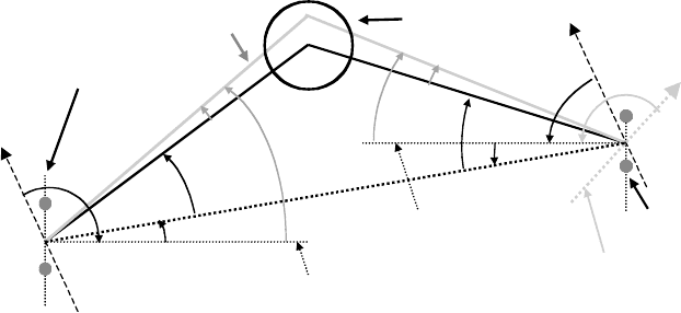
Figure 1.13 shows the angular parameters used in the model. The following
definitions are used:
<
BS
BS antenna array orientation, defined as the difference between the broadside of the
BS array and the absolute North (N) reference direction
V
BS
LOS AoD direction between the BS and MS, with respect to the broadside of the BS
array
I
n,AoD
AoD for the n
th
path (n = 1 … N) with respect to the LOS AoD V
BS
)
n,m,AoD
Offset for the m
th
sub-path (m = 1 … M) of the n
th
path with respect to I
n,AoD
V
n,m,AoD
Absolute AoD for the m
th
sub-path of the n
th
path at the BS with respect to the BS
broadside
<
MS
MS antenna array orientation, defined as the difference between the broadside of
the MS array and the absolute North reference direction
V
MS
Angle between the BS-MS LOS and the MS broadside
I
n,AoA
AoA for the n
th
path with respect to the LOS AoA V
MS
)
n,m,AoA
Offset for the m
th
sub-path of the n
th
path with respect to I
n,AoA
V
n,m,AoA
Absolute AoA for the m
th
sub-path of the n
th
path at the MS with respect to the MS
broadside
v MS velocity vector
V
v
Angle of velocity vector with respect to the MS broadside: V
v
= arg(v)
4190_book.fm Page 19 Tuesday, February 21, 2006 9:14 AM
20 MIMO System Technology for Wireless Communications
For the simulations some general assumptions are made (Table 1.1):
a. Uplink-downlink reciprocity, i.e., the AoD/AoA values are identical
between the uplink and downlink.
b. For FDD systems, random sub-path phases between uplink and
downlink are uncorrelated. For TDD systems, the phases are fully
correlated.
c. Shadowing among different mobiles is uncorrelated.
d. The spatial channel model allows any type of antenna configuration
(e.g., with size smaller than the shadowing coherence distance). In
order to compare algorithms, reference antenna configurations
based on uniform linear array with 0.5, 4 and 10 wavelength inter-
element spacing are used.
e. The composite AS (angle spread), DS (delay spread) and SF(shadow
fading) may be correlated parameters depending on the channel
scenario, and are applied to all the sectors or antennas of a given
base. The AS is composed of 6 × 20 sub-paths, and each has a precise
angle of departure, which corresponds to an antenna gain from each
BS antenna. The SF is a bulk parameter and is common among all
the BS antennas or sectors.
f. The elevation spread is not modeled.
g. To allow comparisons of different antenna scenarios, the transmit
power of a single antenna case is the same as the total transmit power
of a multiple antenna case.
h. The generation of the channel coefficients assumes linear arrays
(although the procedure can be generalized for other array config-
urations).
FIGURE 1.13
BS and MS angle parameters for the 3GPP model [63].
θ
BS
δ
n,AoD
δ
n,AoA
Ω
BS
N
N
Cluster n
Ω
MS
θ
MS
θ
v
BS array broadside
MS array broadside
BS array
MS direction of travel
MS array
Subpath m
v
∆
n,m,AoD
∆
n,m,AoA
θ
n,m,AoA
θ
n,m,AoD
4190_book.fm Page 20 Tuesday, February 21, 2006 9:14 AM

Spatio-Temporal Propagation Modeling 21
The following are assumptions for the macrocell suburban and urban
environments:
a. The macrocell pathloss is based on the modified COST231 Hata
urban propagation model:
TABLE 1.1
Environment Parameters [63]
Channel Scenario
Suburban
Macro Urban Macro Urban Micro
Number of paths (N)666
Number of sub-paths (M) per
path
20 20 20
Mean AS at BS E(X
AS
) = 5° E(X
AS
) = 8°, 15° NLOS: E(X
AS
) = 19°
AS at BS as a lognormal random
variable
X
AS
= 10°(J
AS
x + µ
AS
), x ~ M(0, 1)
µ
AS
= 0.69
J
AS
= 0.13
8°
µ
AS
= 0.810
15°
µ
AS
= 1.18
N/A
J
AS
= 0.34
J
AS
= 0.210
r
AS
= X
AoD
/X
AS
1.2 1.3 N/A
Per path AS at BS (fixed) 2° 2° 5° (LOS and NLOS)
BS per path AoD Distribution
standard distribution
M(0,
X
2
AoD
)
where
X
AoD
= r
AS
X
AS
M(0, X
2
AoD
)
where
X
AoD
= r
AS
X
AS
U(–40°, 40°)
Mean AS at MS E(X
AS, MS
) = 68° E(X
AS, MS
) = 68° E(X
AS, MS
) = 68°
Per path AS at MS (fixed) 35° 35° 35°
MS Per path AoA Distribution M(0, X
2
AoA
(P
r
)) M(0, X
2
AoA
(P
r
)) M(0, X
2
AoA
(P
r
))
Delay spread as a lognormal
random variable
X
DS
= 10°(J
DS
x + µ
DS
), x ~ M(0, 1)
µ
DS
= –6.80
J
DS
= 0.288
µ
DS
= –6.18
J
DS
= 0.18
N/A
Mean total RMS delay spread E(X
DS
) = 0.17 µsE(X
DS
) = 0.65 µsE(X
DS
) = 0.251 µs
(output)
r
DS
= X
delays
/X
DS
1.4 1.7 N/A
Distribution for path delays U(0, 1.2 µs)
Lognormal shadowing
standard deviation, X
SF
8dB 8dB NLOS: 10 dB
LOS: 4 dB
Pathloss model (dB), d is in
meters
31.5 + 35log
10
(d) 34.5 + 35log
10
(d) NLOS:
34.53 + 38log
10
(d)
LOS:
30.18 + 6log
10
(d)
PL dB h
d
BS
[] . .log log=
()
()
©
«
ª
¹
»
44 9 6 55
1000
10 10
ºº
++
()()
45 5 35 46 1 1
13 82
10
1
...log
.log
hf
MS c
00
07hhC
BS MS
()
++.
4190_book.fm Page 21 Tuesday, February 21, 2006 9:14 AM
22 MIMO System Technology for Wireless Communications
where h
BS
and h
MS
are the BS and MS antenna height (in meters), f
C
is carrier frequency (in MHz), d is the distance between MS and BS
(in meters) and C is a constant factor (C = 0 dB for suburban macro
and C = 3 dB for urban micro).
b. Site-to-site SF corelation is 0.5.
The following are assumptions for the microcell environment:
a. The microcell NLOS pathloss is based on the COST 231 Walfish-
Ikegami NLOS model with the following parameters: BS antenna
height 12.5 m, building height 12 m, building to building distance
50 m, street width 25 m, MS antenna height 1.5 m, orientation 30 deg
for all paths, and selection of metropolitan center. With these param-
eters, the equation simplifies to:
PL(dB) = –55.9 + 38*log
10
(d) + (24.5 + 1.5*f
c
/925)*log
10
(f
c
)
The resulting pathloss at 1900 MHz is: PL(dB) = 34.53 + 38*log
10
(d),
where d is in meters. The distance d is at least 20 m. A bulk log
normal shadowing applying to all sub-paths has a standard devia-
tion of 10 dB.
The microcell LOS pathloss is based on the COST 231 Walfish-Ikeg-
ami street canyon model with the same parameters as in the NLOS
case. The pathloss is
PL(dB) = –35.4 + 26*log
10
(d) + 20*log
10
(f
c
)
The resulting pathloss at 1900 MHz is PL(dB) = 30.18 + 26*log
10
(d),
where d is in meters. The distance d is at least 20 m. A bulk log
normal shadowing applying to all sub-paths has a standard devia-
tion of 4 dB.
b. Site-to-site correlation is _ = 0.5.
In [63], the algorithm that generates the model parameters is
explained step by step for the different operational environments.
These parameters are then used to generate the channel coefficients.
For an S element linear BS array and a U element linear MS array,
the channel coefficients for one of N multipath components are given
by a U-by-S matrix of complex amplitudes. The channel matrix for
the nth multipath component (n = 1,…,N) is denoted as H
n
(t). The
(u,s)th component (s = 1,…,S; u = 1,…,U) of H
n
(t) is given by
ht
P
M
Gjkd
usn
nSF
BS nmAoD s nm
,,
,, ,
()
exp sin
=
()
X
VV
,, ,
,,
exp sin
AoD n m
MS n m AoA u
G jkd
()
+
¬
®
¼
¾
()
×
()
+
VV
nnmAoA
nmAoA v
jk t
,,
,,
exp cos
()
()
×
()
()
©
«
ª
ª
ª
v VV
ªª
ª
ª
¹
»
º
º
º
º
º
º
=
¨
m
M
1
4190_book.fm Page 22 Tuesday, February 21, 2006 9:14 AM

Spatio-Temporal Propagation Modeling 23
where
P
n
is the power of the n
th
path.
X
SF
is the lognormal shadow fading, applied as a bulk
parameter to the n paths for a given drop.
M is the number of sub-paths per path.
V
n,m,AoD
is the AoD for the m
th
sub-path of the nth path.
V
n,m,AoA
is the AoA for the m
th
sub-path of the nth path.
G
BS
(V
n,m,AoD
) is the BS antenna gain of each array element.
G
MS
(V
n,m,AoA
) is the MS antenna gain of each array element.
k is the wave number 2U/Q where Q is the carrier wave-
length in meters.
d
S
is the distance in meters from BS antenna element s
from the reference (s = 1) antenna. For the reference
antenna s = 1, d
1
=0.
d
u
is the distance in meters from MS antenna element u
from the reference (u = 1) antenna. For the reference
antenna u = 1, d
1
=0.
+
n,m
is the phase of the m
th
sub-path of the nth path.
㥋v㥋 is the magnitude of the MS velocity vector.
V
v
is the angle of the MS velocity vector.
The pathloss and the log normal shadowing is applied as bulk parameters
to each of the sub-path components of the n path components of the channel.
Also in [63], a method of using polarized antennas in the above model is
presented and the resulting channel characterization is given. Finally, the
model includes options for far scatterer clusters, line of sight and urban
canyon.
References
1. L.M. Correia, Ed. 2001. Wireless Flexible Personalized Communications, COST 259:
European Cooperation in Mobile Radio Research, Chichester: John Wiley &
Sons.
2. R.B. Ertel, P. Cardieri, K.W. Sowerby, T.S. Rappaport, and J.H. Reed. 1998.
“Overview of spatial channel models for antenna array communication
systems,” IEEE Personal Communications Magazine, Vol. 5, No. 1, Feb., pp. 10–22.
3. K. Yu and B. Ottersten. 2002. “Models for MIMO propagation channels: a
review,” Wireless Communications and Mobile Computing, Vol. 2: pp. 653–666.
4. J.C. Liberti and T.S. Rappaport. 1999. Smart Antennas for Wireless Communica-
tions, Upper Saddle River, NJ: Prentice Hall.
4190_book.fm Page 23 Tuesday, February 21, 2006 9:14 AM