Tsoulos George (ред.) MIMO System Technology for Wireless Communications
Подождите немного. Документ загружается.


324 MIMO System Technology for Wireless Communications
MIMO implementation [14], to estimate I and Q branches indepen-
dently. This doubles the number of correlation circuits, but it fits
better to the real-valued signal processing used in the experimental
system.
• OFDM systems are often subject to a residual IQ imbalance in the
RF units. The resulting cross-talk between equally indexed image
carriers in the upper and lower side-band depends, in addition to
the strength of the imbalance, also on the channel coefficient of the
image carrier [15]. When we use the same sequence H
j
(k
)
in both
sidebands, the image carrier may leak signal energy into the desired
carrier, which is likely to cause a certain channel estimation error.
We have occasionally observed ill-reconstructed signal constella-
tions, accordingly, if the channel of the desired subcarrier is faded.
Visibly, the constellations on respective subcarriers become more
stable when the upper and lower side-bands are marked with a
different sequence, allowing also a base-band correction of the
imbalance in the future when the increased complexity becomes
affordable.
Note that these modifications increase the preamble length. The minimal
length is P
= n
Tx
OFDM symbols without and P=
4* n
Tx
training symbols
including all modifications.
11.4 Channel Estimation
The number of channel coefficients to be estimated for MIMO-OFDM is
enormous. In the experimental system, we have explicitly estimated all coef-
ficients between each I and Q input and output with 3 Tx and 5 Rx antennas
and 48 subcarriers, which results in a number of 4 · n
Tx
· n
Rx
· N
= 2880 coeffi-
cients. The above-described preamble has the inherent advantage that we
can get a raw estimate for the coefficients on all subcarriers almost instan-
taneously after the end of the last training symbol. In principle, additional
interpolation between adjacent carriers (see below) is not required.
Raw estimation:
Channel estimation is performed in the frequency domain
using a correlation over multiple OFDM training symbols. Using a separate
correlation circuit (CC) for each of the 2880 coefficients would be prohibi-
tively complex. But since the frequency-domain scrambling is the same for
all Tx antennas, it can be reversed prior to the channel estimation. Then we
have effectively the same sequence on all subcarriers for a given channel
input, and the same CC can be reused for all carriers. This allows an efficient
implementation of the channel estimator, as explained in the following.
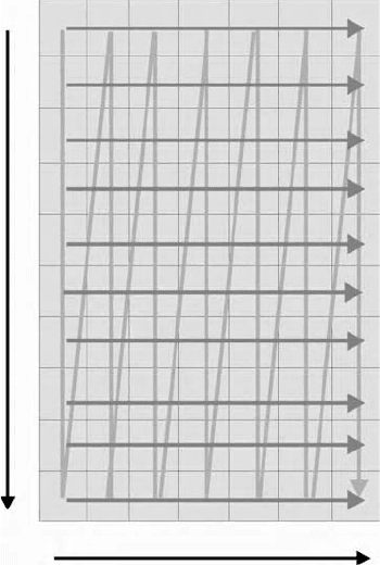
Figure 11.3 shows a frequency-time grid where each column corresponds
to one OFDM training symbol and each row to one subcarrier. After the
4190_book.fm Page 324 Tuesday, February 21, 2006 9:14 AM
Gigabit Mobile Communications Using Real-Time Signal Processing
325
pipelined FFT for each Rx antenna in the FPGA realization, the grid is
scanned column-by-column, as indicated by the zig-zag line. A separate
correlation must now be performed for each subcarrier from OFDM symbol
to OFDM symbol as indicated by the horizontal arrow.
Let us assume that we have a separate memory for each subcarrier and
each pair of inputs and outputs where intermediate results can be stored.
Now the desired correlation is performed in a piecewise manner: If we arrive
at a particular carrier index n
and at OFDM symbol index k
, we recall the last
intermediate result from the memory, then we add or subtract the received
signal, according to the current sign of the Hadamard sequence, and finally
we store the new intermediate result in the memory. Then we go to the next
subcarrier. In this way, one correlation circuit can be reused for all subcar-
riers, for one pair of inputs and outputs, which reduces the complexity by
the factor N
.
However, these three steps (read, add/subtract, write) must be performed
consecutively, which needs a higher clock in the channel estimator than for
other sample rate operations. To avoid this higher clock, the circuit is actually
implemented as a wrapped pipeline using a dual-port RAM and an adder
as shown in Figure 11.4. At first, the scrambling is reversed and the signal
FIGURE 11.3
Frequency-time grid to explain the principle of the channel estimation (see text).
Carrier index
Time index
4190_book.fm Page 325 Tuesday, February 21, 2006 9:14 AM
326 MIMO System Technology for Wireless Communications
is either added to or subtracted from the last intermediate result. The latter
is recalled from port 1 of a dual-port RAM, and the result is stored in port 2.
The idea is then to exchange the two-port address spaces for read and write
operations from training symbol to training symbol, where the address of
each subcarrier is used once in each address space and counted through by
the carrier index n
. All processes are organized in this wrapped pipeline so
that the read, add or subtract and write tasks are effectively performed in a
single cycle. We have operated 4 · n
Tx
· n
Rx
= 60 of these circuits in parallel at
100 MHz in the experimental system. This highly parallel channel estimator
operates very reliably, even in complex FPGA designs. We like to point out
that the realization of the channel estimator using the wrapped pipeline was
one of the key ideas for stable operation of the entire MIMO-OFDM signal
processing core at 100 MHz clock.
Raw estimation error:
The received signal at the i
th
Rx antenna and n
th
subcarrier is given as
(11.6)
where is the channel coefficient to be estimated and the noise at
the receiver. The pilot sequence identifies the j
th
Tx antenna and all
sequences together are normalized as
FIGURE 11.4
Wrapped pipeline structure used to operate the channel estimation at sample clock rate.
Address 1
Dual
port
RAM
Port 2
Port 1
Addresses 1 and 2
are exchanged
from symbol index to
symbol index
Hadamard
sequence at
symbol index t
Scrambling
sequence
at tone n
Received
signal
on
tone n
Change
sign
Adder
Add or
subtract?
Address 2
yk H pk nk
n
i
n
ij
n
j
j
n
n
i
Tx
() () ()= +
=
¨
1
H
n
ij
nk
n
i
()
pk
n
j
()
4190_book.fm Page 326 Tuesday, February 21, 2006 9:14 AM

Gigabit Mobile Communications Using Real-Time Signal Processing 327
(11.7)
Now the channel estimation is performed as a correlation over all consec-
utive OFDM training symbols at the nth subcarrier of interest as
(11.8)
Provided that the sequences are orthogonal
(11.9)
where I
lj
is the Kronecker symbol (I
lj
=1 for l=i and I
lj
=0 elsewhere), one
obtains
(11.10)
Since the pilot tones have just positive or negative sign, the statistics of
the Gaussian noise are not modified by the multiplication in Equation 11.10.
Now the noise is modeled as a random process as
(11.11)
where SNR is the signal-to-noise ratio at one Rx antenna and r a complex
Gaussian number with zero mean and unit variance, then the sum in Equa-
tion 11.5 reduces to
(11.12)
where G is called the estimator gain and is a complex Gaussian random
number with zero mean and unit variance.
pk p
n
n
j
n
N
j
n
n
j
Tx
Tx
()
2
11
1
1
==
¨¨
==
NN
±
{}
1
ˆ
() ()
*
H
nN
P
pkyk
nN
P
H
n
il
Tx
n
l
k
P
n
i
Tx
n
ij
=
=
=
¨
1
ppkpk
nN
P
pk
l
n
k
P
n
j
j
n
Tx
l
n
k
Tx
**
() () () +
==
¨¨
11 ==
¨
1
P
n
i
nk()
pkp k
P
nN
l
n
k
P
n
j
Tx
lj*
() () =
=
¨
1
I
ˆ
() ()
*
HH
nN
P
pknk
n
il
n
il
Tx
l
nn
i
k
P
=+
=
¨
1
nt
NSNR
rt
n
i
kn
i
k
() ()=
1
ˆ
HH
GSNR
NG
P
n
n
il
n
il
n
il
Tx
=+
=
1
N
n
il
4190_book.fm Page 327 Tuesday, February 21, 2006 9:14 AM
328 MIMO System Technology for Wireless Communications
With the above described preamble, the minimum number P
min
of OFDM
training symbols to identify the Tx antennas is n
Tx
. In addition, P
min
must be
a power of 2. By doubling the length of the preamble, one can double G and
correspondingly reduce the raw estimation error.
Interpolation: Actually, Equation 11.12 is the same result as for flat fading
MIMO channel estimation, when each antenna is marked with a sequence
out of an orthogonal set. In OFDM systems, however, there is inherent
redundancy in the channel estimates, which can be used to reduce the chan-
nel estimation error. This method is called interpolation in the following.
The mathematical formulation is based on the elementary observation that
Equation 11.2 states an over-determined set of N equations for the frequency-
domain estimates, with only L variables being the time-domain channel
coefficients. The redundancy can be exploited by first solving this set for the
time-domain coefficients, from which a filtered version of the frequency-
domain estimates is obtained in a second step by discrete or fast Fourier
transform. The algorithm is described in Appendix 11A. For MIMO-OFDM,
it is applied separately for each pair of Tx and Rx antennas.
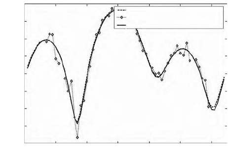
Figure 11.5 shows a simulation result for N = 48 and L = 16, according to
the IEEE 802.11a standard where L is set equal to the cyclic prefix length.
The dashed line corresponds to the true channel, from which we get noisy
estimates on only 48 out of the total number of 64 subcarriers (red dots) after
the raw channel estimation. After application of the interpolation, the esti-
mation error is reduced and the true channel is almost perfectly recon-
structed (solid line).
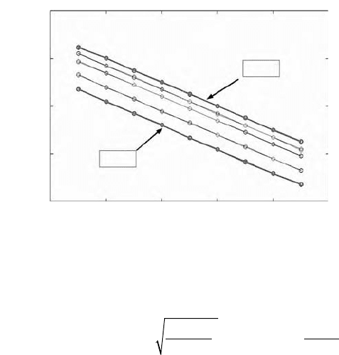
As shown in Figure 11.6, the variance of the channel estimation (CE) error
can be described by an enhanced estimator gain
FIGURE 11.5
The OFDM channel estimation can be enhanced by interpolation of raw estimates.
abs(H) true channel
abs(H) noisy channel estimation
abs(H) interpolated H
Frequency response abs
(
H
f
)
(
dB)
2
0
0 10 20 30 40 50 60
−2
−4
−6
−8
−10
−12
−14
OFDM subcarrier number
4190_book.fm Page 328 Tuesday, February 21, 2006 9:14 AM
Gigabit Mobile Communications Using Real-Time Signal Processing 329
(11.13)
where N is the number of active subcarriers and L the number of multipath
components in the channel. It is obvious from Equation 11.13 that there is a
well-defined tradeoff between the parameters of the channel estimation.
Within these limits, the improved estimator gain can be used to
• Reduce the length of the preamble P
• Reduce the number of subcarriers N on which pilots are transmitted
• Reduce the channel estimation error by using a priori knowledge
about the multipath channel. When L is known in advance, for
instance by exploiting channel data from the most recent frames, L
could be much smaller than the length of the cyclic prefix. So the
estimator gain can be boosted.
The interpolation must be performed once for each pair of Tx and Rx
antennas. In the experimental system, we have not had sufficient resources
for performing the interpolation. The implementation on the current DSP
consumed a significant part of the processing power, due to the large number
of 15 complex-valued channel frequency responses to be interpolated. So we
have skipped the interpolation routine in favor of a faster adaptation to the
time-variant channel. Equivalently, we have used a longer preamble as
described above to improve the raw estimates. According to Equation 11.12,
the estimator gain in the experimental system is G = 64/3 = 13.3 dB. Further
FIGURE 11.6
Simulation for the variance of the channel estimation error in Gaussian noise.
SNR (dB)
Variance of CE error σ
2
ΔH
−10
10
−6
10
−4
10
−2
10
0
10
2
10 20 30 40
64
16
4
2
1
0
G = 1
G = 64
ˆ
HH NH
GSNR
N
n
il
n
il
Hn
il
n
il
n
il
=+ =+
X
)
1
G
PN
nL
Tx
=
4190_book.fm Page 329 Tuesday, February 21, 2006 9:14 AM

330 MIMO System Technology for Wireless Communications
research is concerned with extending this algorithm to a bunch of subcarriers
(chunk). Chunkwise interpolation is a key component in future MIMO-
OFDM signal processing chains. It is needed for systems with large numbers
of subcarriers to distribute the calculation of weights onto multiple DSPs,
as explained in the next section, and to reduce the computational complexity
accordingly.
11.5 Adaptation to the Time-Variant Channel
Adaptation to the time-variation of the fading channel is challenging with
the limited DSP processing power in the experimental system. First results
with a single-carrier MIMO system [14] already indicated that substantial
effort is needed here to fulfill the mobility requirements even for indoor
environments.
For the MMSE detector, an update of the N weights matrices for the space–
frequency post-processing is needed in a fraction of the channel coherence
time. To get a rough idea of the required processing power, we have imple-
mented the calculation of the pseudo-inverse matrix in MATLAB 5.3 and
counted the required number of floating point operations (FLOPs). For a
MIMO system with 2 Tx and 2 Rx or 4 Tx and 4 Rx, one needs 419 or 4.800
FLOPs, respectively, to get the matrix (HH
H
)
-1
H
H
for a single carrier needed
in Equation 11.4 for X
2
= 0.* Using these values, the required processing
power P
DSP
is lower bounded by
(11.8)
which gives 10 and 115 MFLOPs/s in the two examples above when the
number of subcarriers and the frame length are 48 and 2 ms, respectively.
So the adaptation to the time variation is, in principle, feasible for moderate
numbers of subcarriers and antennas with current DSPs claiming peak pro-
cessing powers of more than 1 GFLOPs/s.
But DSPs are a special kind of processor. In principle, they may perform
multiple add- and multiply-operations as well as memory accesses in a single
cycle, which makes them favorable for operations with large matrices and
vectors. Only in such applications and with highly optimized code does a
DSP approach the performance limit claimed in the data sheet. Our dedicated
optimization of the MIMO algorithms on the DSP is described in detail in
[17]. Here we report some quantitative results as a benchmark of what is
* Note that MATLAB is based on the highly optimized LAPACK matrix-vector routines. The
results obtained in this way may be optimistic for a DSP implementation, where, to our knowl-
edge, routines with a truly comparable performance are not yet commercially available.
P
N FLOPs
T
DSP
frame
>
4190_book.fm Page 330 Tuesday, February 21, 2006 9:14 AM
Gigabit Mobile Communications Using Real-Time Signal Processing 331
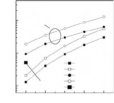
feasible with the experimental system. The performance bounds in the two
bottom lines in Figure 11.7 have been derived from an analysis of the MMSE
and zero forcing algorithms. The data on the time axis have been measured
with the floating-point DSP TI 6713 clocked at 225 MHz. We roughly need
150 or 400 µs for the 2 Tx and 2 Rx or 4 Tx and 4 Rx configurations,
respectively, to renew the MMSE weight matrices for all 48 subcarriers, which
is shorter than the channel coherence time in indoor scenarios, as required.
Note that additional time (384 µs) is needed twice in the experimental sys-
tem: to transfer the channel estimates and MMSE filter weights from and to
the FPGA, respectively. The transfer time is due to the slow external memory
interface between the DSP and the FPGA. An attempt with the Greville
algorithm [18] in assembly language has reduced the value for the 2 Tx and
2 Rx system down to 50 µs, but for this case the numbers of antennas is not
variable. Note the increasing gap to the performance bound toward smaller
matrix dimensions where the pipelined multiply-and-accumulate operations
in the DSP are less effective than for larger matrices. Pipelining is, in general,
more effective when large numbers of identical operations can be performed
consecutively.
Future mobile systems may have a larger number of subcarriers, and they
may need faster adaptation to the channel variation than our experimental
system. According to Equation 11.8, the required processing power scales
with the ratio of the number of subcarriers and the frame length, which is
a favorable characteristic of OFDM. More processing power will conse-
quently be needed.
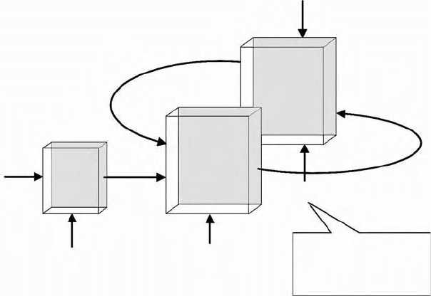
It is therefore proposed to use multiple DSPs connected to the FPGA or
ASIC in a star configuration as sketched in Figure 11.8. Each DSP is respon-
sible for a certain subset of subcarriers, and it has an individual connection
to the respective channel and weight matrices, so that the transfer time and
FIGURE 11.7
Measured times needed to track the multipath channel using the TI 6713 DSP at 225 MHz.
Total time for 48 carriers
(
ms)
Number of transmit antennas
Assembler
program
TI 6713/225 DSP
ZF theory
ZF assembler
MMSE theory
MMSE measured
ZF measured
2 3 4 5 6
1
0.1
0.01
C program
4190_book.fm Page 331 Tuesday, February 21, 2006 9:14 AM
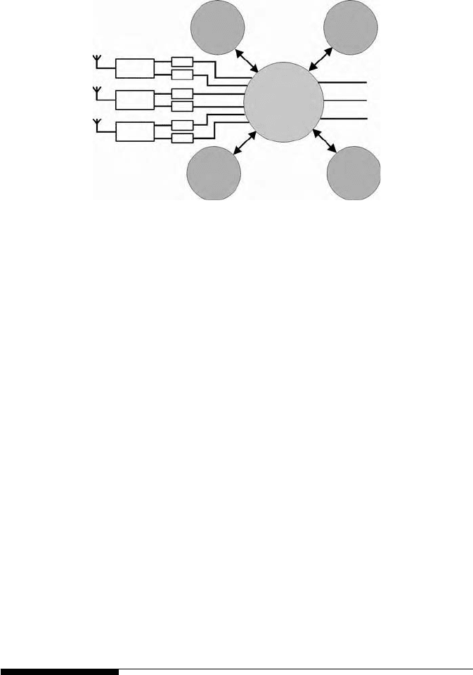
332 MIMO System Technology for Wireless Communications
computational effort can be shared among the DSPs. With this star config-
uration, the engineer can trade off hardware costs against mobility.
Intuitively, interpolation of the weight matrices between adjacent subcar-
riers might be a promising option to speed up the adaptation to the time-
variant channel [19]. However, the gain of currently known interpolation
techniques becomes noticeable only when the delay spread of the wireless
channel is rather small, relative to the CP duration. The fixed base-point
interpolation in [19] causes an error floor, which can be steered using an
adaptive step width between base points [20] or even avoided by using
perfect interpolation as shown in [21,22]. A detailed complexity analysis [23]
confirmed that there are few scenarios where the algorithms proposed in
[21,22] actually realize a reduced computational complexity. As observed in
[20], this is true only when the delay spread is very small. A mathematical
analysis of the reasons, therefore, is given in [21]: The interpolation of the
channel matrix needs L base points but it takes n
Tx
· L base points for the
channel inverse matrix, which is equal to the total number of 48 subcarriers
used for 3 Tx antennas in the 802.11a standard when L is set equal to the
cyclic prefix length of 16. Based on what is currently known about the inverse
matrix interpolation, we feel that the pragmatic approach used in our exper-
imental system, to optimize the calculation of the MMSE weight matrix for
the DSP processor architecture and applying this routine independently for
all subcarriers, is an efficient solution for most cases.
11.6 Data Reconstruction
In the optimal approach described in Section 11.2, the pre- and post-process-
ing requires linear matrix-vector multiplications to be performed individu-
ally for each subcarrier. Also the linear MMSE detector requires this
FIGURE 11.8
A star of DSPs can be used around an FPGA to speed up the channel tracking.
DSP DSP
DSP DSP
FPGA
RF
RF
RF
User
Data
A/D
A/D
A/D
A/D
A/D
A/D
4190_book.fm Page 332 Tuesday, February 21, 2006 9:14 AM
Gigabit Mobile Communications Using Real-Time Signal Processing 333
operation. So it is straightforward to equip the detection unit with this
elementary operation. For each data stream, a scalar product with an indi-
vidual weight vector must be realized after the FFTs for each received signal
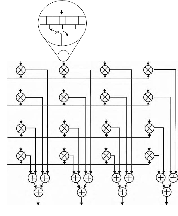
vector. To realize an instantaneous reconstruction of the streams, a pipelined
matrix-vector multiplication unit is implemented as sketched for a 2 Tx and
2 Rx MIMO-OFDM configuration in Figure 11.9. The signals Y
n
i
incoming
from the left are the received signals for subcarrier index n leaving the
pipelined FFT unit subcarrier by subcarrier. Odd indices i = 2 · k – 1 denote
the real part of the complex-valued signal from the kth receive antenna, and
even indices i = 2 · k the imaginary part from that antenna, where k is a
FIGURE 11.9
The MIMO-OFDM data reconstruction uses a pipelined matrix-vector multiplication unit. In-
puts are the I and Q signals from each Rx antenna (Y, left), outputs are the reconstructed data
signals (X,
ˆ
bottom).
X
n
2
X
n
3
X
n
4
Y
n
2
W
n
12
Y
n
3
Y
n
4
W
n
14
X
n
1
Y
n
1
W
n
13
W
n
11
W
n
22
W
n
24
W
n
23
W
n
21
DSP
W
6
W
5
W
4
W
3
W
2
W
1
W
7
W
n
32
W
n
34
W
n
33
W
n
31
W
n
42
W
n
44
W
n
43
W
n
41
4190_book.fm Page 333 Tuesday, February 21, 2006 9:14 AM