Tsoulos George (ред.) MIMO System Technology for Wireless Communications
Подождите немного. Документ загружается.


334 MIMO System Technology for Wireless Communications
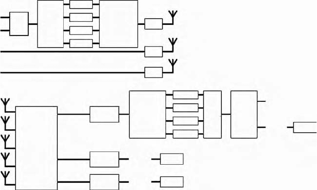
natural number. In the example shown in Figure 11.9, each signal branch is
distributed to four multipliers for which dedicated hardware building blocks
in the FPGA have been used. All multiplications are performed simulta-
neously (i.e., in one 10 ns cycle), and the results are added pairwise in a
subsequent pipeline until a stream is reconstructed. Due to the pipelining,
the final result is obtained after a short delay depending on the number of
antennas. The entire data reconstruction with 3 Tx and 5 Rx requires 60
simultaneous multiplications (in one cycle) for 10 received and 6 transmitted
I and Q signals and four cycles for pairwise executed additions, resulting in
only 50 ns delay after the corresponding subcarrier signals leave the pipe-
lined FFT units, which is negligible compared to the OFDM symbol duration
of 0.8 µs.* So the data reconstruction unit performs the required 100 million
matrix-vector multiplications per second continuously in real time.
The major challenge is that the weight matrices differ from carrier to carrier
and need to be exchanged rapidly. This is shown exemplary for the weight
W
n
21
in Figure 11.9. Approximately once per frame, the frequency response
of each weight is written as a vector by the DSP into a dual-port RAM
assembled from the dedicated hardware memory blocks in the FPGA. The
second port of the dual-port RAM is connected to the dedicated multiplier
used. Now the address of the weight in the vector is counted through at 100
MHz clock synchronous with the increasing subcarrier index n of the incom-
ing signals (leaving the FFT unit subcarrier by subcarrier). In this way, the
matrix vector multiplication pipeline is reused for all subcarriers. The num-
ber of multipliers needed is related only to the numbers of antennas used
while the memory effort scales in addition with the number of subcarriers.
The rapid exchange of weights is a key idea enabling the implementation
of MIMO-OFDM with current FPGAs at 100 MHz bandwidth as shown in
the experimental system. Even higher bandwidths may be possible using
the same technique in an ASIC clocked at higher speed, accordingly. The
spatially multiplexed data streams appear separated from each other after
the matrix-vector multiplication unit. The subsequent signal processing can
be organized in parallel using conventional pipelined OFDM receiver pro-
cessing chains. System integration is straightforward (see Figure 11.11).
Therefore, we have organized the weight matrices for all carriers in register
pages assembled of 60 dual-port RAM blocks, where each RAM block con-
tains the weights for all subcarriers for one input-output pair and is located
next to the corresponding multiplier. The weights are written once per 2 ms
frame into the RAM blocks by the DSP using the outer port. Via the inner
port, the matrix-vector pipeline reads out the corresponding weight for the
current subcarrier and pair of input and output once per sample clock cycle.
In the next cycle, it switches to the next weight for the next subcarrier by
incrementing the weight address. This switching is performed simulta-
neously for all 60 weights. Once per OFDM symbol, hence, all weight matrices
* The FFT and IFFT units are implemented in parallel for all antennas using an FPGA core mod-
ule from XILINX. The pipelined units need about 1.5 OFDM symbol durations (1.2 µs) to provide
the output.
4190_book.fm Page 334 Tuesday, February 21, 2006 9:14 AM

Gigabit Mobile Communications Using Real-Time Signal Processing 335
are consecutively used in the right order. The number of subcarriers that can
be handled so is limited by the number of the Block-RAM units in the FPGA.
The current FPGA design can handle up to 256 subcarriers without using
more Block-RAM units. For more subcarriers, the weight memory blocks
must be assembled from the available units in the FPGA.
11.7 Framing, Mapping, Channel Coding, and Real-Time
Data Interface
The experimental system uses 48 data subcarriers out of a total number of
64. The sampling clock of the complex base-band signals is 200 MSPS both
in the I and Q branches and the processing clock after the digital filtering is
100 MHz (which is called the sample clock). The CP covers 160 ns, which is
sufficient for small rooms. The OFDM symbol duration is 0.8 µs.
Data are continuously transmitted and received in frames with a fixed
length of 2 ms with no additional pauses between the frames. The structure
of the 1 Gbit/s frame is shown in Figure 11.10. It consists of 64 training
symbols for the channel estimation, an idle gap of 16 symbols, a data block
with 2400 symbols, and another idle gap of 20 symbols. With 64-QAM
modulation and three antennas, we transmit 864 bits per symbol (4818). The
2400 data symbols per 2 ms block, hence, correspond to a payload data rate
of 1036.8 Mbit/s.
The channel coding concept is shown in Figure 11.11. The payload is taken
over from the data source, scrambled and multiplexed with pseudo-random
data. Then the stream is split into four parallel streams individually encoded
using a convolutional code with a constraint length of 7 as in the IEEE 802.11a
standard. In the experiments, channel coding with rate ½ is used. The
encoded data are fed into a pseudo-random interleaver with a block length
of 288 bytes of encoded data. With 64-QAM modulation (48 · 6 bits/symbol),
the blocks are mapped onto eight consecutive OFDM symbols. The inter-
leaving covers more symbols when the number of bits per symbol is reduced,
FIGURE 11.10
Structure of the 1 Gbit/s frame. The structure is the same for all antennas.
Structure of 1.0368 Gbps-frame
259200 byte payload
2400 OFDM symbols 64 QAM
2 ms = duration of 2500 OFDM symbols
32 C -
preambles
64 OFDM
symbols
Idle gap
16 OFDM
symbols
Idle gap
20 OFDM
symbols
4190_book.fm Page 335 Tuesday, February 21, 2006 9:14 AM
336 MIMO System Technology for Wireless Communications
as for 16-QAM and QPSK modulation. The encoded stream is passed through
the modulator and then used at the first antenna only. The other two anten-
nas are loaded with pseudo-random data. At the receiver, the reconstructed
stream of the first antenna is at first de-mapped and de-interleaved. Then
the original coded stream is reconstructed, de-multiplexed, and fed into four
parallel Viterbi decoders (realized in the second FPGA with an FPGA soft-
ware core module provided by XILINX) with a trace-back length of 96,
according to the multiplexing at the transmitter. The parallel coding concept
is required to overcome the speed limitations of the Viterbi decoder core in
the FPGA, which can handle up to 100 Mbit/s, depending on the code rate.
The parallel decoding concept is obviously scalable to 1 Gbit/s, but the
hardware effort scales linearly with the data rate. A third FPGA would be
required to fully decode all streams. We feel that encoding the first stream
is sufficient to proof feasibility. With the full concept, it would, of course, be
helpful to interleave over all antennas, which better exploits the transmit
diversity.
The MIMO-OFDM detector has knowledge about the post-detection SINR
on each subcarrier and each stream. Once per frame, this information is
quantized and delivered from the DSP to the Viterbi decoder to enable soft-
decision decoding (one hard plus two soft bits). The soft decoding has an
obvious effect on the performance: besides the higher coding gain, it better
exploits the multipath diversity. Finally, the decoded payload is de-scrambled
and fed into the data sink.
Data source and sink are added to the system for public demonstrations
and realized with two Real-time Linux-based PCs running a simplified
medium access control (MAC) protocol stack up to the Internet protocol (IP)
layer where the payload is bridged to an Ethernet interface. Measurements
FIGURE 11.11
Parallel decoding is used to overcome the speed limitations in the FPGA.
enc 1
enc 2
enc 3
enc 4
Demux
Mux
Payload
PRBS
Payload
PRBS
PRBS
PRBS
Antenna 1
Antenna 2
Antenna 3
Pseudo-
random
interleaver
mod
mod
mod
De-
interleave
MIMO-
OFDM
signal
processing
Stream 1
Stream 2
Stream 3
Demod
Demod
Demod
PRBS
PRBS
BER 2
BER 1
BER 3
dec 1
dec 2
dec 3
dec 4
Mux
Demux
4190_book.fm Page 336 Tuesday, February 21, 2006 9:14 AM
Gigabit Mobile Communications Using Real-Time Signal Processing 337
showed stable operation up to 80 Mbit/s, indicating that the current MAC
concept must of course be revised and simplified in the future to enable the
envisaged Gbit/s data rates on top of the MAC protocol stack. Two notebook
computers are coupled to the data source and sink PCs via Ethernet, respec-
tively, and a conventional IP network is operated, with the unidirectional radio
link in between. The reverse link is replaced by an Ethernet cable. In this way,
MPEG-encoded HDTV video transmission and data transfer are enabled.
11.8 Implementation, Complexity, and System Integration
The payload data from the source PC are coupled into the base-band pro-
cessing FPGA via flat ribbon cable connected to a dedicated 64-bit PCI
interface card. The Tx signal processing is distributed over two Virtex2-6000
FPGAs placed on the Chip-it Gold platform [24]. While the first FPGA con-
tains the data mapping and forward error correcton encoder, the second one
contains the three OFDM transmit chains. Each complex base-band signal is
connected to two 12-bit AD9753 digital-to-analogue (DA) converters operat-
ing at 200 MSPS on a small printed circuit board (see Figure 11.12) having a
large number of short parallel connections to the input-output ports at the
FPGA. Three such boards are used to realize the three Tx chains.
The operation of OFDM links requires radio front-ends with negligible IQ
imbalance. The base-band signals are up-converted to a 900 MHz intermedi-
ate frequency (IF) using three AD8349 IQ modulators, which have been care-
fully adapted to each DA converter, so that the phase error is below 0.1° and
base-band responses in I and Q branches are quasi-identical. The IF signal is
up-converted in a second stage to the 5.26 GHz radio frequency. The received
signals are down-converted to the same IF as used at the transmitter. AD8347
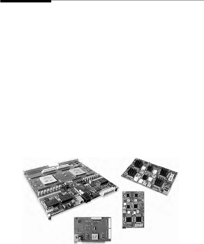
FIGURE 11.12
Commercially available components are used for the reconfigurable signal processing platform.
FFP basic
FPGA board
Four-channel
ADC board
Two-channel
DAC, two-channel
ADC board
PCI interface board
4190_book.fm Page 337 Tuesday, February 21, 2006 9:14 AM

338 MIMO System Technology for Wireless Communications
IQ demodulators are used to down-convert the IF signals to the complex
base-band, and the IQ mismatch in each demodulator is carefully adapted to
each analogue-to-digital (AD) converter, so that the cross-talk between image
carriers is negligible in the entire OFDM transmission chain. For the matching
procedure, see [25]. For lower bandwidth designs, one may consider digital
IQ modulation, which is not yet available for 100 MHz bandwidth.
At each Rx antenna, the base-band signals are sampled at 200 MSPS with
two AD9430 AD converters placed on a small printed circuit board having
a large number of connections in parallel to the input-output ports at the
FPGA. The ADC board already hosts four converters (see Figure 11.12), and
three such boards are used in the experimental system for the 5 Rx chains.
For the receiver base-band processing, a dedicated rapid prototyping
platform is used (FFPbasic, see Figure 11.12 and [25]) carrying two Virtex-
2/PRO-100 FPGAs (speed grade 6). The whole MIMO-OFDM base-band pro-
cessing, except the adaptation to the time-variant channel, is implemented in
the first FPGA, while the other realizes the de-interleaving, decoding, and
de-mapping, as well as the interface to the host PC.
The adaptation to the time-variant channel is implemented in a floating-
point DSP TI 6713 placed on a standard TI development board clocked at
225 MHz clock and coupled to the FPGA using the external memory interface
(EMIF). The DSP is asynchronously coupled, and it can read from and write
to dedicated memory blocks in the FPGA (see [14]).
In the table below, the resources used in the FPGA are reported after
compiling our MIMO-OFDM software core with Version 6.3 of the XILINX
ISE development tool (from the FFT inputs to the separated data streams),
for the 3 Tx, 5 Rx configuration. The 1 Tx, 1 Rx configuration is given in
brackets as a reference. It can be observed in Table 11.1 that the FPGA is not
fully occupied, which allows efficient routing of the design and reliable
operation at the 100 MHz sample clock. In the trial implementation described
in this chapter, the focus is to demonstrate that the MIMO-OFDM signal
processing (being the heart of the new system) is feasible in real time. Syn-
chronization is initially realized by cables. Over-the-air synchronization for
MIMO-OFDM is very similar to conventional OFDM, except that the per-
formance can be enhanced by exploiting spatial diversity. It has been added
later in the experimental system together with an enhanced number of sub-
carriers and the hardware effort required for this will be reported elsewhere.
TABLE 11.1
FPGA Resources Used for the Implementation of the 3 Tx, 5 Rx (1 Tx, 1 Rx)
Signal Processing
FFT
Channel
Estimation
Data
Reconstruction
Total
(Integrated)
BlockRAMs 95 (19) 60 (4) 60 (4) 215 (27) of 444
Multipliers 45 (9) — 60 (4) 105 (13) of 444
Slices 9878 (2401) 1272 (48) 2904 (24) 15.235 (2.473) of 44.036
4190_book.fm Page 338 Tuesday, February 21, 2006 9:14 AM

Gigabit Mobile Communications Using Real-Time Signal Processing 339
In lower bandwidth designs, parts of the components can be reused, such
as for the FFTs, which can be consecutively used for all antennas at a corre-
spondingly higher clock. Also, the logic in the channel estimator can be
reused, when the correlation circuit is implemented once for each Tx antenna
and used consecutively for all Rx antennas with correspondingly increased
clock speed. In the matrix-vector multiplication engine, one may reconstruct
the parallel streams consecutively at a correspondingly higher clock. How-
ever, the memory effort does not reduce in this way for both the channel
estimator and the data reconstruction unit, since it depends on the number of
subcarriers and on the antenna configuration. No components are reused in
the experimental system. The maximal clock of the integrated MIMO-OFDM
processing core is predicted by the XILINX ISE synthesis tool as 147 MHz.
As already mentioned, the sample rate processing is fully pipelined, in
order to allow a continuous signal flow. So one cannot assign a time con-
sumption to a required operation, as this is familiar for block-wise signal
processing preferred in DSP-based implementations. In a pipelined FPGA
implementation, there is just latency for each operation since the output of
one operation is the input of the next operation in the chain, and operations
are performed simultaneously on consecutive signals. For the sake of com-
pleteness, we report the latency of important system functions in Table 11.2.
The latency for the de-interleaving and decoding is measured as the time
between the first bit input of a data block at the de-interleaver and the first
bit output at the Viterbi decoder for 16-QAM modulation, and it is larger
for QPSK and smaller for 64-QAM.* The given value is intended here as a
rule-of-thumb for estimating the total latency which varies, accordingly.
TABLE 11.2
Computation Times and Latencies of Different Processing Steps in the 3 Tx, 5 Rx
Signal Processing
Function
Computation
Time Latency Comment
IFFT/FFT No 1.2 µs each Symbol-wise pipelined
XILINX FFT core, Ver. 2.1
QAM mapping/demapping No 10 ns Carrier-wise pipelined
uses look-up tables
Synchronization — — Not yet implemented
MIMO channel estimation 51.2 µs equal to
preamble length
No Wrapped pipeline
Calculation of MMSE
weight matrices
0.5 ms in DSP No Application of weights is
delayed by one frame
Data reconstruction Carrier-wise
pipelined
50 ns See text
De-interleaver and decoder Pipelined 3.4 µs 16-QAM, see text
* De-interleaving and decoding operate on large bit sequences and input registers must first be
filled before output can be generated. This is faster at higher data rates.
4190_book.fm Page 339 Tuesday, February 21, 2006 9:14 AM
340 MIMO System Technology for Wireless Communications
Elementary system functions are supervised using the USB 2.0 interface
on the Rx FPGA board, which is frequently read out with a local monitoring
terminal (LMT) running on a notebook computer. The LMT makes available
samples from the reconstructed signal constellations on each stream, the
mean powers between each Tx and Rx antenna, the singular values of the
channel matrices, as well the good-put, which is the number of correctly
transmitted bits per second, as well as the un-coded and coded bit error
rates. Long-term statistics for these quantities are recorded in a log-file, for
off-line evaluation purposes.
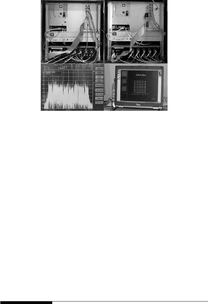
The integrated transmitter and receiver racks are shown in Figure 11.13,
as well as a received signal spectrum and an LMT screenshot in the 64-QAM
mode. Each rack contains an integrated RF unit (bottom) and a base-band
unit (top). The base-band unit contains the PC (left), the FPGA board, and
(at the Rx only) the DSP (right). The received signal spectrum and the
separated 64-QAM signal constellations have been measured after transmit-
ting the signals over the air. The actual good-put is 1035.8 Mbit/s, and the
un-coded bit error rate is 10
–4
. The experimental system was presented at
the 3GSM World Congress, February 14–17, 2005 in Cannes, France.
11.9 Transmission Experiments
Next, we report on over-the-air measurements with the experimental system
in a mobile communications scenario. Measurements are conducted in a
FIGURE 11.13
Top left: 3-antenna transmitter. Top right: 5-antenna receiver. Bottom left: Received signal
spectrum in a 100-MHz frequency span. Bottom right: Local monitoring terminal (LMT) show-
ing the received 64-QAM signal constellations of the three data streams, for all subcarriers. The
first stream is zoomed.
4190_book.fm Page 340 Tuesday, February 21, 2006 9:14 AM
Gigabit Mobile Communications Using Real-Time Signal Processing 341
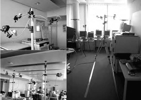
15 × 7 × 2.8 m
3
office room in a SIEMENS building at Werinher-Strasse in
Munich, Germany. At the Tx, three antennas are used addressing different
field directions (see Figure 11.14, top left). The omni-directional Tx antennas
(360°h, 25°v, 20° down tilt) are placed at 2-m height on a wheeled photo
stand. The stand is moved like a cable car using a DC motor and guided by
a rail on a 4-m track through the room at 1-m distance from the short front
of the room (see Figure 11.14, right). The movement over 70 wavelengths at
the 5.26 GHz carrier frequency forms well-reproducible channel statistics.
The Rx sector antennas (65°h, 35°v) were fixed at irregular positions approx-
imately looking toward the Tx in a line forming a distributed antenna sce-
nario (Figure 11.14, bottom, left). The distance between the Tx track and the
Rx line was about 4 m.
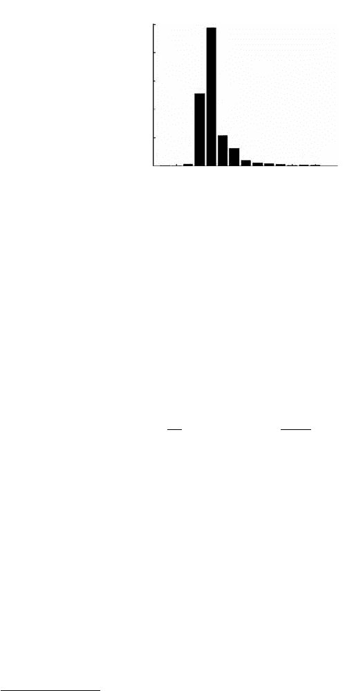
We first used the built-in channel estimator to obtain information about
the broadband MIMO channel. The channel is recorded along the whole
measurement track. In Figure 11.15, the average power delay profile is
shown. The time axis is scaled in samples and one sample corresponds to
10 ns.
It is observed that the peak is much wider than a sample. The 100 MHz
bandwidth obviously resolves multiple paths, mostly due to the multipath
propagation in the room. When the paths are independently faded, the larger
bandwidth is a valuable source of multipath (or frequency-) diversity, which
is a new feature of broadband compared to narrow-band MIMO systems.
Not only is the capacity a figure of merit in these systems but also the
multipath diversity can be exploited to improve the system performance.
Diversity effects are traditionally observed in the bit error rate curves at high
SNR. But one may observe them also in the cumulative distribution of the
channel capacity.
FIGURE 11.14
Measurement scenario. Top left: Tx antenna configuration. Bottom left: Rx antenna configura-
tion. Right: The Tx is moved along a line through the room.
4190_book.fm Page 341 Tuesday, February 21, 2006 9:14 AM
342 MIMO System Technology for Wireless Communications
The capacity distribution is obtained from the measured channel data as
follows. The data are at first corrected for the frequency response of the
transmitter and receiver chains, which exhibit some ripple due to the ana-
logue and digital base-band filters. Since we have not observed significant
slow fading on the relatively short track, the mean received power is aver-
aged over both all carriers and all snapshots, which gives the normalization
factor M in Equation 11.9. Finally, the broadband capacity is obtained using
the formula
(11.9)
The narrowband capacity immediately follows from Equation 11.9 for
N = 1, i.e., for a single carrier.* Results are shown in Figure 11.16. The statis-
tics for the broadband capacity are based on calculating Equation 11.9 with
N = 48 for 296 snapshots along the track. For the narrowband case, the
capacity of all 48 channels for each subcarrier is individually calculated for
all 296 snapshots, which forms a smoother statistic, due to the larger ensemble.
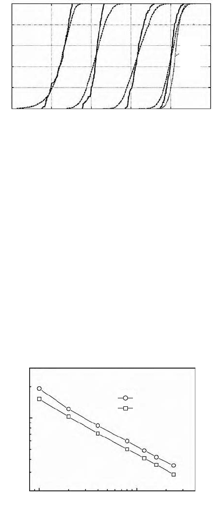
As expected, the cumulative distribution is shifted right when the numbers
of antennas are increased. The slope is slightly steeper, and the curve is
shifted right with additional Rx antennas (compare the 3 Tx, 3 Rx and the
3 Tx, 5 Rx configurations). The benefit of the multipath diversity becomes
obvious since the broadband distributions (solid lines) are significantly
steeper than in the narrow-band case (dashed lines). For the 3 Tx, 5 Rx
FIGURE 11.15
Average power delay profile along the measurement track.
* Actually, we have used the real-valued representation of Equation 11.9, according to our meas-
ured channel data, which means that the real-valued channel matrices have the dimensions
(2n
r
× 2n
t
) so that the normalization factor M and the capacity are multiplied by two and divided
by two, respectively.
Averaged received power
(
a.u.)
10
10
8
8
6
6
4
4
2
2
12
14
16
0
0
P
at
h in
de
x
×10
5
C
N
SNR
n
broadband
n
N
t
nn
H
=+
©
«
=
¨
1
2
0
1
log det 1HH
M
ªª
¹
»
º
4190_book.fm Page 342 Tuesday, February 21, 2006 9:14 AM
Gigabit Mobile Communications Using Real-Time Signal Processing 343
configuration, we have also plotted a simulation result for the Rayleigh
fading channel with four paths (dotted line). Note that the measured capac-
ities are slightly smaller than the numerical results, most likely due to the
presence of the LOS signal.
The steeper capacity distribution in multipath fading is well known from
simulations [26]. It can quantitatively be described using the standard devi-
ation of the distribution. In Figure 11.17, simulation results are plotted vs.
the number of paths L, for the 3 Tx, 3 Rx and 3 Tx, 5 Rx configurations. There
is a certain offset between the curves, depending on the number of excess
antennas at the Rx. But in general, the width of the capacity distribution is
approximately inversely proportional to L, which is not so obvious in
FIGURE 11.16
Statistics of the narrow- (dashed lines) and broad-band capacities (solid lines) in the measured
scenario for various antenna configurations at SNR = 20 dB. A simulation curve (dotted line)
for the 3 × 5 configuration for the Rayleigh fading channel with four independently and iden-
tically distributed paths is given as well.
FIGURE 11.17
Standard deviation of the capacity distribution for different numbers of resolved paths.
Capacity (bits/s/Hz)
Cumulative probability
0 5
10 15 20 25
1 Tx,
1 Rx
2 Tx,
2 Rx
3 Tx,
3 Rx
3 Tx,
5 RX
0
0.2
0.4
0.6
0.8
1
Sim
ula
tion
3 Tx, 5 Rx
Standard deviation of the
capacity(bps/Hz)
1
110
Simulation 3 × 3
Simulation 3 × 5
Multipath MIMO
SNR = 20 dB
Number of resolved paths L
4190_book.fm Page 343 Tuesday, February 21, 2006 9:14 AM