Velten K. Mathematical Modeling and Simulation: Introduction for Scientists and Engineers
Подождите немного. Документ загружается.


4.9 A Sample Session Using Salome-Meca 285
4.9.4
Postprocessing Step
The solution procedure described in the last section generates an entity called
Post-Pro in Salome-Meca’s object browser (Figure 4.19a). To use this entity for
postprocessing, activate Salome-Meca’s Post-Pro module using the drop-down list
shown in Figure 4.9a as before. Then, opening the ‘‘Post-Pro’’ entity in the object
browser as shown in Figure 4.19a, the context menu on ‘‘0, INCONNUE’’ allows
you to display the solution in various ways. (The french word ‘‘INCONNUE’’
reminds us of the fact that Code_Aster, the software behind Salome-Meca’s Aster
module, is a French development, see Section 4.8.) Figure 4.19b shows how the
plots (an isosurface plot in this case) are displayed in Salome-Meca’s VTK 3D viewer.
A number of options can be used to affect the way in which the plots are displayed,
such as arbitrary 3D rotations using the mouse.
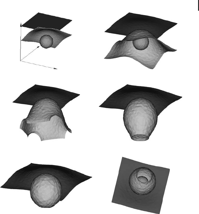
Figure 4.20a and b shows the solution displayed using cut plane plots,thatis,
plots made up of planes inside the domain, which are colored corresponding to
the values of the unknown. Although Figures 4.20a and b show screenshots in
black and white, you can see that the darkest colors – which correspond to the
lowest temperatures – are concentrated around the cold sphere inside the cube,
compare Figure 4.1b and the description of Problem 6 above. The various kinds of
plots offered in the postprocessing context menu (Figure 4.19a) can be combined
arbitrarily as required. For example, Figure 4.20c shows a combination of the
isosurface plot from Figure 4.19b with a cut plane plot. Depending on the PDE that
is solved, Salome-Meca’s postprocessing module also provides a number of other
classical plots that can be used to visualize PDE solutions, such as arrow plots and
streamline plots.
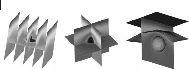
Since we are restricted to black and white plots here, the solution of Problem 6is
best discussed using isosurface plots. Note that an isosurface plot shows a surface
made up of points where some quantity of interest (temperature in this case) attains
some given, fixed value. Figure 4.21 shows a number of isosurface plots where the
(a) (b)
Fig. 4.19 (a) Postprocessing context menu. (b) VTK viewer showing isosurfaces.
286 4 Mechanistic Models II: PDEs
(
a
)(
b
)(
c
)
Fig. 4.20 (a) and (b) Solution of Problem 6 displayed using
cut planes. (c) Combination of a cut plane with isosurfaces.
temperature of the isosurfaces has been varied in the various subplots, such that
we can virtually ‘‘move through the solution’’ along these subplots. Figure 4.21a
shows three isosurfaces corresponding to 20, 15, and 10
◦
C (from top to bottom).
Since 20
◦
C was prescribed on the top surface of the cube in Problem 6, the 20
◦
C
isosurface corresponds exactly to this top surface of the cube, and hence this is a flat
surface as it can be seen in the figure. The 10
◦
C isosurface, on the other hand, is an
approximately spherical surface, which surrounds the 0
◦
CsphereinFigure4.1b
like a wrapping. This suggests that the isosurfaces referring to temperatures below
10
◦
C constitute a sequence of nested (approximate) spheres, that is, the radius
of these isosurfaces approaches the radius of the 0
◦
CsphereinFigure4.1bas
the temperature approaches 0
◦
C. You can easily verify this using Salome-Meca’s
Post-Pro module as described above. Finally, the isosurface corresponding to 15
◦
C
in Figure 4.21a is located inside the cube somewhere between the 10 and 20
◦
C
isosurfaces, and its shape can also be described as lying somewhere between the
other two isosurfaces. Observing the shape of this intermediate isosurface through
the plots in Figure 4.21a–e, you can see how its shape gradually deforms toward
a spherical form. Similar to the cut planes discussed above, plots of this kind are
very well suited to understand the results of 3D FE computations.
4.10
A Look Beyond the Heat Equation
As was explained above, differential equations arise naturally in science and
engineering in many cases where the processes under consideration involve rates
of changes of the quantities of interest (Note 3.1.1). Not surprisingly, hence, PDEs
are applied in a great number of ways in science and engineering. To give you an
idea of PDEs ‘‘beyond the heat equation’’, a few classical applications of PDEs are
treated in this section: diffusion and convection processes (Section 4.10.1), porous
media flow (Section 4.10.2), computational fluid dynamics (CFD) (Section 4.10.3),
and structural mechanics (Section 4.10.4). Among these applications, CFD is
perhaps the ‘‘most classical’’ application of PDEs in the sense that it involves
4.10 A Look Beyond the Heat Equation 287
(a) (b)
(c) (d)
(
e
)(
f
)
z
y
x
Fig. 4.21 Solution of Problem 6: (a) Iso-
planes corresponding to 20, 15, and 10
◦
C
(from top to bottom). (b)–(e) Gradual
decrease of the isoplane temperatures (top
isoplane temperatures in (b)–(e) are 16, 15,
14, and 13
◦
C, respectively). (f) A look into
(d) from the bottom, showing the spherical
isosurface that can be seen in (a) and (b)
inside the pear-shaped isosurface.
many applications that have gained attention in the public, such as meteorological
flow simulations on the earth’s surface, or the simulation of air flow around cars,
airplanes and space shuttles. You should note, however, that there is also a great
number of PDE applications in fields where you probably would not expect it, which
includes applications in economics such as the famous Black–Scholes equation that
is used as an option pricing model, and which can be transformed into the form
of the heat equation [170, 171]. Another aspect that cannot be treated here in
sufficient detail is the coupling of differential equations, that is, the coupling of
PDEs with PDEs, PDEs with ODEs, or differential equations with other types of
mathematical equations. This is an important issue for the simple reason that

288 4 Mechanistic Models II: PDEs
real systems usually involve a coupling of several phenomena. An example is
fluid–structure interaction [167], that is, the coupling of the PDEs of CFD with the
PDEs of structural mechanics (see sections 4.10.3 and 4.10.4, and the example in
[5]) or the coupling of the PDEs describing porous media flow with the ‘‘free flow’’
described by the Navier–Stokes equation (see Sections 4.10.2 and 4.10.3 and the
examples in [172, 173]).
4.10.1
Diffusion and Convection
In a sense, a look beyond the heat equation is a look at the heat equation: A number
of different phenomena can be treated by this equation, which includes general
diffusion phenomena as well as porous media flow models (Section 4.10.2). To
derive the general diffusion equation, let us write Fourier’s law (Equation 4.22), in
a different notation as follows:
q(x, t) =−D(x) ·∇N(x, t) (4.120)
This equation is known as Fick’s first law [170], where q ∈ R
3
is the diffusion flux,
for example, in (g m
−2
s
−1
)or(molm
−2
s
−1
), D ∈ R
3x3
is the diffusion coefficient
matrix, e.g. in (m
2
s
−1
), and N is the concentration of a substance, e.g. in (g m
−3
)
or (mol m
−3
).
Fick’s first law pertains e.g. to a situation where there is a tank filled with a
fluid in which some substance is dissolved. Equation 4.120 says that the diffusion
flux of the substance is proportional to the gradients of its concentration, and
that this flux will always be directed toward regions of low concentration. Note
that Fourier’s law describes the diffusion of heat in a similar way. In Section 4.2,
the heat equation was derived from Fourier’s law by an application of the energy
conservation principle. Since Fick’s first law refers to the diffusion of the mass
of a substance rather than to the diffusion of energy, mass conservation must be
applied instead of energy conservation here. This can be done in a similar way as
was done in Section 4.2.2, that is, by balancing the mass flows in a small control
volume, which leads to the diffusion equation [174]
∂N(x, t)
∂t
=∇
D(x) ·∇N(x, t)
(4.121)
Except for different notation and interpretation, this equation is identical with
the heat equation 4.23. It can be solved, for example, using Salome-Meca and the
procedure described in Section 4.9.
Equation 4.121 holds in situations where the fluid is at rest. In many practical
cases, however, the fluid will move during the diffusion process, which means
that the concentration of the fluid changes due to the combined effect of diffusion
and convection. Examples include fermentation processes, such as the wine

4.10 A Look Beyond the Heat Equation 289
fermentation process discussed in Section 3.10.2. As it was discussed there,
temperature control is an important issue in fermentation processes. Usually, this
is achieved by cooling down certain parts inside the tank, and a standard question
is which particular configuration of these cooling parts should be used in order
to achieve a desired temperature distribution at minimal costs. To answer this
question, we need to compute the temperature distribution that results from a
given configuration of those cooling parts. To do this, it would not be sufficient if
we would just apply the heat equation 4.23, since there are substantial movements
of the fluid inside the fermenter, which are caused by density gradients as well
as by the natural evolution of carbon dioxide bubbles during the fermentation
process [175].
A convection flow field v(x) = (v
x
(x), v
y
(x), v
z
(x)) (m s
−1
) generates a convective
flux J(x)(e.g.in(gm
−2
s
−1
)) of the substance, which can be written as [139]
J(x, t) = v(x)N(x, t) (4.122)
Combining Equations 4.120 and 4.122, the overall flux of the substance becomes
q(x, t) + J(x, t) =−D(x) ·∇N(x, t ) + v(x)N(x, t) (4.123)
Applying mass balance to this flux as before, the convection–diffusion equation is
obtained:
∂N(x, t)
∂t
=∇
D(x) ·∇N(x, t) − v(x)N(x, t)
(4.124)
This equation can be further generalized to include source terms that can be
used to describe situations where the substance is supplied or destroyed in certain
parts of the tank [139]. To compute the temperature distribution in a fermenter for
a given convective flow field v(x), we would use this equation in the form
∂T(x, t)
∂t
=
1
Cρ
∇
K(x) ·∇T(x, t) −v(x)T(x, t)
(4.125)
that is, we would just reinterpret Equation 4.124 in terms of the heat equation 4.23.
To get acquainted with the convection–diffusion equation, you can try R’s
SoPhy package, a package contributed by Schlather [176]. SoPhy solves the
one-dimensional convection–diffusion equation:
∂N(z, t)
∂t
= D
∂
2
N(z, t)
∂z
2
− v
∂N(z, t)
∂z
(4.126)
Here, z corresponds to the vertical direction, v is the convective flow velocity in the
z direction, and N is, for example, the concentration of a pollutant that is dissolved
in water. See [177, 178] for the application of
SoPhy to pollutant transport in soils.

290 4 Mechanistic Models II: PDEs
4.10.2
Flow in Porous Media
A great number of systems in nature and technology involve porous media. For
example, the soil below our feet is a good example of a porous medium: it consists
of solid material such as sand and stones as well as of ‘‘empty space’’ (pores)
between the solid material. Other examples of porous media are: biological tissues
such as bones, fleece materials such as diapers or other hygienic products, all kinds
of textile materials, cements, foams, ceramics, and so on. Panta rhei (everything
flows) is an insight that is usually attributed to the Greek philosopher Heraclitus
and applied to porous media it means that the pore space within these materials is
not just a useless ‘‘empty space’’. Rather, it serves as the flow domain of one or even
several fluids in many cases, and indeed many porous media related questions and
problems that are investigated in science and engineering refer to flows through
porous media. The first systematic investigation of fluid flow through porous media
has been performed by the French scientist and engineer Henry Darcy when he
was involved in the construction and optimization of the fountains of the city of
Dijon in France [179]. His experiments led him to what is called Darcy’s law today,
which can be written in modern notation as [69, 180, 181]
q(x, t) =−
1
μ
K(x, t) ·∇p(x, t) (4.127)
where q ∈ R
3
is the Darcy velocity (m s
−1
), μ is the (dynamic) viscosity (Pa·s),
K ∈ R
3x3
is the permeability matrix (m
2
), and p is the (fluid) pressure (Pa).
Here, the viscosity μ basically expresses the internal friction of a fluid or its resis-
tance to deformations as a result of stresses such as shear or extensional stresses
[180, 182]. Low-viscosity values mean that a liquid is ‘‘thin’’ and flows easily (such
as water for which μ = 10
−3
Pa·s), while high viscosity values refer to ‘‘thick’’
fluidssuchascornsyrup(μ>1Pa·s)that exhibit a much larger resistance to flow.
Obviously, this is a really important quantity in the entire field of computational
fluid dynamics (e.g. it will appear in Section 4.10.3 as a part of the Navier–Stokes
equations).
The Darcy velocity q is also known as seepage velocity, filtration velocity, superficial
velocity,orvolumetric flux density in the literature. To understand it, imagine a
one-dimensional flow experiment comprising of a water column on top of a porous
material. As the water flows through the porous medium e.g. driven by gravity,
the top surface of the water column will gradually come down toward the porous
medium, and it is exactly this superficial velocity of the water column that is described
by the Darcy velocity. This macroscopic velocity must be distinguished from the
microscopic, intrinsic average velocity of the fluid within the pores of the porous
medium. If we use v to denote the latter velocity, the relation between v and q can
be expressed as
q(x) = φ(x)v(x) (4.128)

4.10 A Look Beyond the Heat Equation 291
where φ is the porosity of the porous medium, which expresses the fraction of the
pore space within the porous medium in percent. All these quantities are usually
defined throughout the porous medium. For example, the Darcy velocity is defined
even outside the pore spaces of the medium, which is achieved using an averaging
over so-called representative elementary volumes [69, 180]. Darcy formulated Equation
4.127 just as a phenomenological model that fits the data, but it has been shown
that this equation can be interpreted as expressing conservation of momentum
[183]. As in the case of the diffusion equation (Section 4.10.1), a second equation
expressing mass conservation is needed. Again, this can be done in a similar way
as in Section 4.2.2, that is, by balancing the mass flows in a small control volume,
which leads to
φ
∂ρ
∂t
+∇·
ρq
= 0 (4.129)
where ρ (e.g. in (g m
−3
)) is the fluid density. Assuming an incompressible fluid,
we have ∂ρ/∂t = 0, and hence Equations 4.127 and 4.129 imply
∇
K(x) ·∇p(x)
= 0 (4.130)
if we assume stationary conditions and a constant viscosity. Again, we have a perfect
analogy with the stationary heat equation: Darcy’s law, Equation 4.127, corresponds
to Fourier’s law, Equations 4.22, and 4.130 corresponds to the stationary heat
equation (Equation 4.23 with ∂T/∂t = 0).
The permeability matrix K in Equation 4.130 expresses the ease of flow through
the porous medium. Basically, relatively small pressure gradients will suffice to
initiate a flow with some given velocity in the case of high permeability values, while
larger pressure gradients will be needed in the case of low permeability values. As
amatrix,K can be interpreted similar to the thermal conductivity matrix that was
discussed in Section 4.2.5. Again, Equation 4.130 can be solved, for example, using
Salome-Meca and the procedure described in Section 4.9.
4.10.2.1 Impregnation Processes
In [184–186], Equation 4.130 has been used to optimize the impregnation of
mica tape-based insulations. These insulations are used to insulate steel bars inside
large turbines that are used for high-voltage electrical power generation. They are
manufactured in two steps. In a first step, a mica tape is wound in several layers
around the steel bar. Figure 4.22a shows a schematic cross section through such
a mica tape winding. As a result of the winding process, the mica tapes – which
correspond to the black lines in the figure – form staircase-like structures. In the
second step of the manufacturing procedure, the mica tape winding is impregnated
with an epoxy resin. During impregnation, the main resin flow is through the pore
spaces between the mica tapes (see the arrows in Figure 4.22a). Now the problem
is that the permeability of the mica tapes as well as the permeability of the winding
as a whole is extremely small, which means that the impregnation is proceeding
extremely slow. In the worst case, some regions of the winding may remain
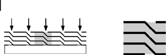
292 4 Mechanistic Models II: PDEs
Steel bar
Periodic
b.c.
Periodic
b.c.
p
1
p
2
(
a
)(
b
)
Fig. 4.22 (a) Cross section through mica tape insulation
with periodicity cell (gray rectangle). (b) Boundary conditions
in the periodicity cell.
unimpregnated, which can cause expensive electrical failures during the operation
of the turbines. In [184–186], simulations of the impregnation process based on
Equation 4.130 have been used to optimize the impregnation process in a way that
helps to avoid this kind of impregnation failures.
To simulate the fluid flow in the winding using Equation 4.130, boundary
conditions must be applied at the boundaries of the winding. At the top surface
of the winding (where the epoxy resin enters the winding) and at its bottom
surface (where the winding is in contact with the steel bar) the pressures can be
prescribed that are driving the fluid flow, for example, a constant p
1
at the top
of the winding and p
2
< p
1
at its bottom (Figure 4.22b). Since the winding has
a periodic structure, it suffices to do the flow computation in a periodicity cell
(Figure 4.22a). This periodicity cell represents the winding in the sense that the
whole winding can be generated by successively attaching copies of the periodicity
cell. When the flow computation is done in the periodicity cell, so-called periodic
boundary conditions are applied at its left and right ends, that is, in the direction of
the periodicity of the structure. Mathematically, these periodic boundary conditions
basically identify the corresponding periodic boundaries, in this case by equating
the pressure values at the left end of the periodicity cell with the corresponding
values at its right end. As the example shows, the size of the flow domain and,
hence, the resulting computational effort can be reduced substantially by the
application of periodic boundary conditions. Before setting up a flow computation,
one should thus always analyze the periodicity of the system under investigation,
and apply periodic boundary conditions if possible. A great number of systems in
science and engineering are periodic similar to the example.
Many other industrial processes involve the impregnation of a porous material
with a fluid. An example is the resin transfer molding (RTM) process,whichis
used to produce fiber-reinforced plastic materials that are used for all kinds of
high-technology applications such as aerospace structures. In this process, a textile
preform is placed into a closed mold which is then impregnated with low-viscosity
(easily flowing) thermosetting polymers. Similar to above, computer simulations
have been used to optimize this process in order to avoid problems such as
incomplete impregnation. Again, Equation 4.130 can be used in many cases [91,
187–189].

4.10 A Look Beyond the Heat Equation 293
4.10.2.2 Two-phase Flow
The above porous media flow model can be used only for one-phase flow, that
is, in situations where there is just a single fluid in the pores of the porous
medium. Of course, there are many situations which involve the flow of several
fluids through a porous medium at the same time. An important application that
has substantially driven the development of multiphase porous media flow models
in the past is oil exploration [190], which involves the simultaneous flow of oil,
water, and gases through porous soil and rock structures. As an example, let us
consider the two-phase flow of water and air in a porous medium (e.g. in a soil).
One of the simplest assumptions that one can make here is that the air pressure is
approximately constant, which leads to the Richard’s equation
∂(ψ(x, t))
∂t
−∇·
K(ψ(x, t))∇(ψ(x, t) + z)
= 0 (4.131)
where is the volumetric water content (1), ψ = p/(ρg) is the pressure head (m),
p is the pressure in the water phase (Pa), ρ is the water phase density (kg m
−3
),
g ≈ 9.81 is the gravitational acceleration (m s
−2
), and K ∈ R
3x3
is the hydraulic
conductivity (m s
−1
).
Basically, this equation is derived similar to Equation 4.130, using the above
assumptions and a separate application of momentum and mass conservation to
each of the fluid phases [191, 192]. Note that ψ is just the usual pressure p rescaled
in a way that is frequently applied by people who are using Richard’s equation
(such as soil scientists). This rescaling allows ψ to be interpreted in terms of water
columns [191].
4.10.2.3 Water Retention and Relative Permeability
(ψ)andK(ψ) are empirical relations that express material properties of the flow
domain. (ψ)iswhatsoilscientistscallthewater retention curve. It expresses the
external pressure that needs to be applied to a soil in order to obtain some given
value of volumetric moisture content, which is an important soil characteristic
particularly with respect to the water supply to plants or with respect to soil
aggregate stability.
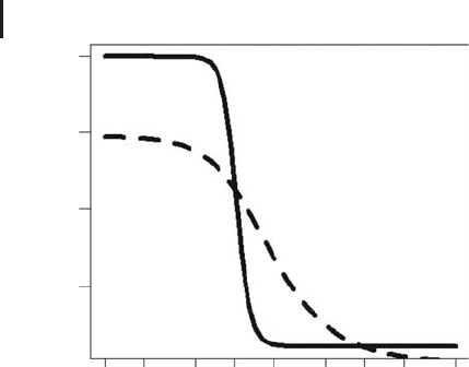
Figure 4.23 shows example water retention curves for a sand and a sintered
clayey material. As the figure shows, increasingly high pressures need to be applied
in order to achieve small moisture values. Also, it can be seen that higher pressures
are required to achieve small moisture values in the clayey material. Basically, this
expresses the simple fact that sand soils are more coarse grained compared to
clayey materials, which means that the capillary forces that are retaining the water
in a porous material are smaller in a sand soil [194]. Figure 4.23 has been drawn
using the code
Mualem.r in the book software (Appendix A), which is based on the
Mualem/van Genuchten model [194]
(ψ) =
r
+
s
−
r
1 +(α|ψ|
n
)
1−1/n
(4.132)
294 4 Mechanistic Models II: PDEs
0.4
0.3
0.2
0.1
Θ(y)
y (kPa)
0.1
0.5
2.0
5.0
20.0
Fig. 4.23 Water retention curves for a sand (solid line,
r
= 0.022,
s
= 0.399, α = 0.93, n = 8.567) and a sin-
tered clayey material (dashed line,
r
= 0,
s
= 0.295,
α = 0.605, n = 2.27). Parameters from [193], figure drawn
using
Mualem.r.
where
r
is the residual water content (1),
s
is the saturated water content (1),
α is an empirical parameter (m
−1
), and n > 1 is an empirical parameter related to
the pore-size distribution (1). The residual water content
r
is the volumetric water
content that cannot be removed from the soil even if very high external pressure is
applied, whereas the saturated water content
s
is the volumetric water content in
the case where the soil is fully saturated (i.e. no air is present in the pore space).
α is related to the inverse of the air entry suction, which is the smallest external
pressure that must be applied to remove water from a fully saturated soil.
The empirical relation K(ψ) in Equation 4.131 is related with the notion of relative
permeability. In multiphase flow situations, two things must be distinguished:
•
K
1
: the permeability of a porous medium with respect to a
fluid that entirely fills the pores of the porous medium (fully
saturated case);
•
K
2
: the permeability of a porous medium with respect to a
fluid in the presence of one or several other fluids
(unsaturated case).
Usually, K
2
will be smaller than K
1
since less pore space is available for the fluid
under consideration in the unsaturated case. The corresponding reduction of the
saturated permeability is expressed as the relative permeability, K
2
/K
1
. Applied
to Equation 4.131, this means that the permeability K will depend on the water
saturation, or, via Equation 4.132, on the pressure head, ψ. This dependence can
again be described using appropriate empirical relations such as the Corey equation
[183, 190].