Yam, Kit L. (ed.). The Wiley encyclopedia of packaging technology
Подождите немного. Документ загружается.

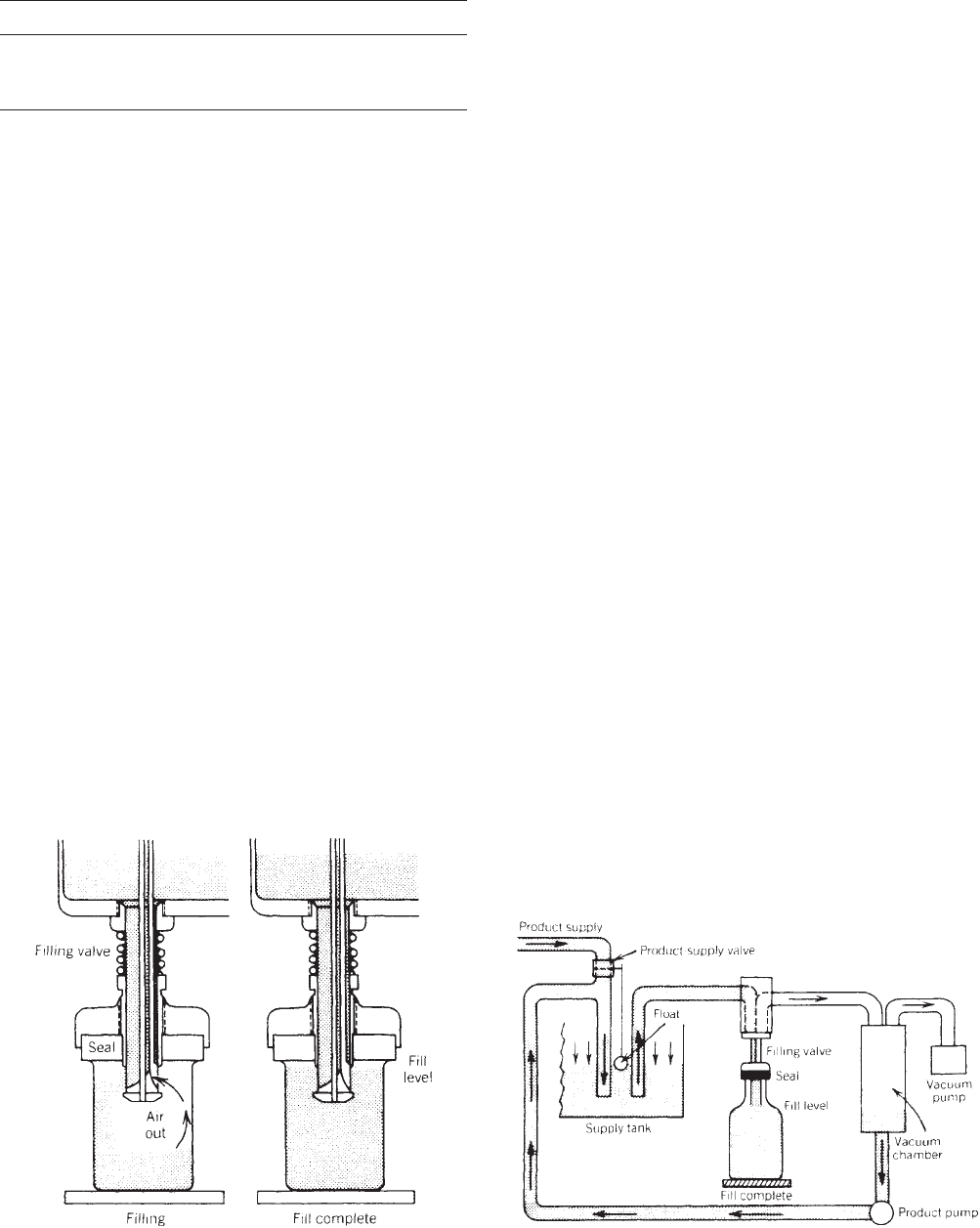
Balanced-Pressure Fillers. The first three of the seven
mentioned above are balanced-pressure fillers, in which
product flows through a valve into the container from a
tank of liquid located above the container, and air from the
container is vented back to the headspace in the tank
through the same valve. The typical embodiment of such a
filling system, gravity filling—one of the simplest and
most reliable—is illustrated in Figure 1. As the filling
takes place through the sleeve-type valve illustrated,
liquid flows from the tank through the liquid port into
the container, and air within the container flows up the
vent tube to the top of the tank. The container fills product
to an exact level determined by the position of the vent
port relative to the bottle. Any liquid in the vent from a
previous filling cycle is returned to the product in the tank
by the air flowing up the vent tube. If necessary, air or
vacuum may be used to clean the vent before the start
of fill.
A modification of pure gravity filling is the gravity–
vacuum filler. In such a system, a low vacuum is main-
tained in the headspace in a sealed tank. When the
container is brought into sealing contact with the filling
valve and the valve is opened, the pressure of air in the
container helps force any product in the vent back into the
tank, accelerating the start of the filling process. The use
of gravity–vacuum fillers also prevents the loss of product
that would occur if a chipped or slightly broken container
were filled. This savings is of particular advantage when
filling more expensive products.
To fill thin-walled plastic containers, such as 1-gal (3.8-L)
milk bottles , a pulsating vacuum in the tank is sometimes
used to cause the container walls to flex in and out, assisting
the foam in moving up the vents . The pulsations must be
timed so that a container is not flexed inward at the position
at which it is ready to break away from the filling valve,
because this could cause underfill.
Thousands of different styles of filling nozzles, which
use single ports, multiple ports, screens, sliding tubes, or
check valves, are offered by various manufacturers. All
these styles are designed to achieve the maximum produc-
tion rate with the fewest number of filling valves and
provide greater accuracy of fill. The selection of nozzle
type is probably best left to the judgment of the machinery
manufacturer, on the basis of experience and product
testing.
Counterpressure fillers for carbonated beverages are
discussed elsewhere (see the Filling machinery, carbo-
nated liquid article).
Unbalanced-Pressure Fillers. Unbalanced-pressure fil-
lers use a difference in pressure between that on the
liquid to be filled and on the vent that permits air in the
container to escape during the filling process. The usual
combinations are listed in Table 1. The use of unequal
pressure permits higher rates of product flow than possi-
ble with the balanced-pressure fillers. Unequal pressure is
particularly advantageous when filling containers with
small openings, viscous products, or large containers.
Unbalanced-pressure filling has the disadvantage of
requiring an overflow-collection/product-recirculation
system, in contrast to the relative simplicity of balanced-
pressure fillers. Higher liquid-flow rates do not necessarily
result in faster filling because the additional foam gener-
ated by rapid entry of product into the container must be
drawn off through the overflow system to obtain accurate
filling-level control.
A schematic diagram of a typical vacuum filler is shown
in Figure 2. The supply tank may be located either above
or below the container to be filled. After the filling valve
seals against the container and the valve opens, the
vacuum on the vent draws the liquid into the container
up to the filling level. Usually, a substantial quantity of
Figure 1. Pure gravity filling. (Courtesy of Horix.)
Table 2. Container Positioning Methods
and Configurations
Positioning Method Configuration
Manual
Automatic, in-line Single or dual lane
Automatic, rotary Single or dual lane
Figure 2. Pure vacuum filling. (Courtesy of PMMI.)
448 FILLING MACHINERY, LIQUID, STILL
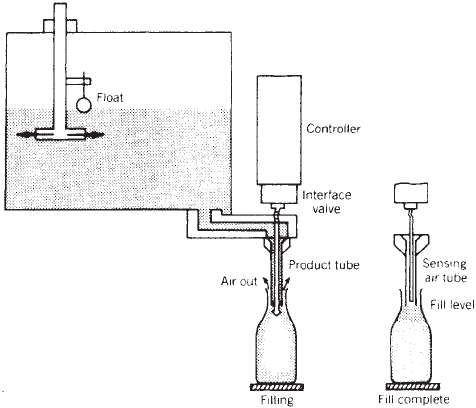
liquid is drawn into the vent, which leads to an overflow
tank. Product is recovered in the overflow tank and then
recycled.
The prevacuumizing filler is a special form of vacuum
filling. On such a filler, a vacuum is first drawn in the
container, evacuating the air. The valve then permits
liquid to enter the container. Because such a system is
complex and expensive, it is normally used only when
liquid is being added to solids already in the container.
Certain solids, such as peach halves, trap air. Such air
entrapment may be eliminated by use of a prevacuumiz-
ing filler.
In an unbalanced-pressure gravity filler, the product-
supply tank and the overflow tanks are open to the atmo-
sphere, but the product tank is located above the container
and the overflow tank is located below the container,
permitting the differential pressure achieved by the dif-
ference in elevation to cause product flow. Such a filler is
necessarily rather restricted in its ability to adapt to
varying products and containers because the pressure
difference is established solely by the product-tank and
overflow-tank locations. Fillers of this type are not
common.
A pressure filler is similar to a vacuum filler except that
pressure is applied to the product. This may be achieved
either by pressurizing the headspace over a tank or by
direct pumping of the product to the filling valve. In the
most common form of pressure filling, the product is
pressurized, and the overflow tank is open to the atmo-
sphere. Such a system allows unbalanced fill without
vacuum. This is desirable when vacuum cannot be drawn
on the product.
For example, drawing a high vacuum on alcoholic
beverages can reduce the alcoholic content of the bever-
age. Applying a vacuum to a hot product, such as juice at
2001F (931C) causes the liquid to flash. If desired, both the
product and the vent can be maintained above atmo-
spheric pressure, but with a higher pressure on the
product. Such a filler is often used for filling lightly
carbonated products, such as certain wines, using the
pressure to retain the low carbonation in the product.
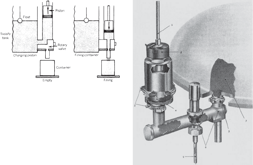
Unsealed Container Filling Systems.
Level-Sensing Fillers. Level-sensing fillers fill containers
to a controlled level without sealing the container, as
shown in Figure 3. Such a filling technique eliminates
product recirculation and allows filling to a level in plastic
containers that would bulge out or flex inward if pressure
or vacuum were applied to the sealed container. A level-
sensing filler uses some type of sensing means, typically a
flow of ultra-low-pressure air. The rising liquid level in the
container blocks air-flow, triggering a control system that
shuts off product flow to the container. Such control
mechanisms, which are required at each filling nozzle,
are expensive, but high rates of fill may be achieved
because there is no product overflow and no foam to be
removed. Electronic sensing is also available.
Piston Volumetric Fillers. Currently, unsealed-container
fillers are the most common, and volumetric filling is a
frequently used method. In view of this popularity, many
different kinds of volumetric fillers are available. For
volumetric filling, piston fillers are most widely used.
Table 1 indicates four subclasses of piston fillers, depend-
ing on the orientation of the pistons, specifically vertical or
horizontal, and inlet arrangement.
1. Cylinder Vertical, Closed Ends. One station of a
typical vertical-cylinder rotary filling machine is
illustrated in Figure 4. The valve(s) controlling the
product flow between the supply tank, measuring
chamber, and dispensing nozzle may have either a
rotary or a reciprocating motion. The rotary style,
which is more common, is illustrated. The product is
drawn into the cylinder from the liquid-supply tank
when the piston moves upward. The valve then
rotates to permit the premeasured volume in the
cylindrical chamber to flow into the container.
Usually, either a direct mechanical drive from a
cam track or an air cylinder is used to stroke the
piston. If an air cylinder is used to drive the piston,
controls are usually such that the piston does not
cycle if a container is not in place. This eliminates
moving the liquid back and forth between the mea-
suring chamber and the supply tank, a situation
that is usually undesirable and may cause product
breakdown with foods such as mayonnaise. It is not
easy to uncouple a mechanically driven piston.
2. Cylinder Vertical, Open-End Inlet. In an alternative
design, product enters vertical volume chambers
through cylinders open at their upper ends, with a
cam drive located below. A nonrotating plate with an
orifice allows product to enter the open-ended cylin-
ders at the appropriate position during the rotation
of the filler bowl. Such a configuration is mechani-
cally complex and generally considered difficult to
clean.
Fillers of this
type have the advantage, how-
ever, of being able to handle products containing
sizable solids in suspension.
Figure 3. Level-sensing filling. (Courtesy of PMMI.)
FILLING MACHINERY, LIQUID, STILL 449
3. Cylinder Horizontal. Measuring cylinders may be
mounted horizontally. Usually single-ended, they
are similar to vertical cylinders in operating princi-
ple. They are frequently found on in-line, large-
volume fillers to avoid excessive height for such
machines. A volume cylinder may also be double
ended, with inlets and outlets at both ends. Product
under pressure flows into one end, which causes a
floating piston to move and expel the liquid in the
opposite end of the cylinder into the container. In
some fillers, the double-acting cylinder may be used
for a single fill, and the first half of the fill comes
from one end. The flow pattern is then reversed to
discharge product from the other end of the cylinder
for the second half of the fill while the first end is
being filled for the next cycle.
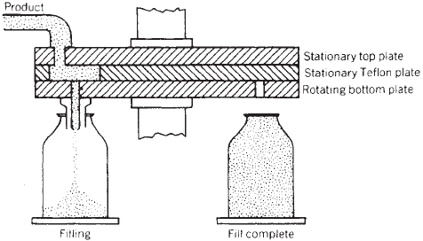
Rolling-Diaphragm Volumetric Fillers. The volumetric
fillers described above normally have some type of a
seal, such as V or O rings, between the pistons and
cylinder walls. An alternative method for measuring
volume is to use a rolling diaphragm; a typical arrange-
ment can be observed in Figure 5. The diaphragm pro-
vides an absolute seal and also eliminates the friction
contact of a seal with a cylinder wall. Such sliding causes
abrasion and particle generation, which is seldom impor-
tant, but minimizing particulate generation is important
in the packaging of intravenous solutions and injectable
drugs. Rolling-diaphragm volumetric fillers often employ
flexible diaphragms or pinch valves to control product flow
to and from the measuring chambers.
Displacement-Ram Volumetric Fillers. Another method
for dispensing a specific volume of liquid is to use a
displacement ram. The ram enters one end of a cylinder
through a seal of some type, but the displacement ram
does not touch the inside of the cylinder wall. An external
air cylinder drives the ram, which displaces a controlled
volume from the cylinder into the container. Such fillers
are easy to clean.
Volume-Cup Fillers. Cup-type volumetric fillers operate
by first transferring the product from an open tank into
measuring cups of precise volume. Depending on the
design, each cup may be filled to a level matching that of
the tank, or the cup may fill to overflow and then rise
above the level of liquid in the tank. Each valve then opens
at the bottom, permitting liquid to flow from the cup into a
container. Although such fillers are appropriate only for
low-viscosity liquids that do not cling to the sidewalls of
the cups, for suitable applications the volume-measuring
method is accurate, inexpensive, and reliable. Various
volume-adjustment systems are provided. These fillers
are usually rotary and are often designed to be easily
changed, by means of a change of filling valves, to gravity
or gravity–vacuum filling.
Turbine-Meter Volumetric Fillers. The amount of liquid
dispensed from a nozzle can be measured by placing a
turbine flowmeter in the line ahead of the nozzle. Such
meters, which include an electronic counting and control
system to start and stop flow, are accurate but expensive
and are generally used only for filling large containers,
i.e., Z5 gal (Z19 L).
Figure 4. Piston volumetric filling. (Courtesy of PMMI.)
Figure 5. Rolling-diaphragm volumetric filling: (1) volume ad-
justment rod; (2) precision volume adjustment; (3) quick-discon-
nect design; (4) volume-chamber diaphragm; (5) product tube; (6)
valve seats; (7) product supply manifold. (Courtesy of Horix.)
450 FILLING MACHINERY, LIQUID, STILL
Positive-Displacement Volumetric Fillers. Viscous liquids
may be moved directly from a supply system through a
positive-displacement pump into a container. Volumetric
measurement is achieved by accurately controlling the
number of revolutions made by the pump. An auger may
be used as the pump mechanism.
Peristaltic-Pump Volumetric. Peristaltic pumps are of-
ten used to fill sterile liquids, as they are easy to clean and
have no sliding parts that might contaminate the product
being filled.
Weight Fillers. On gross-weight fillers, each fill station
is fitted with a weighing device, typically a beam scale,
which acts to shut off product flow when a predetermined
weight has been reached. Each scale is set for the max-
imum weight of container and contents. Adjustment for
other containers and content weight may be made by
adding special weights to each filling platform.
By using a load cell as the weighing device, the weight
is electronically measured continuously, and liquid flow is
stopped at a predetermined weight. With microprocessor
controls, the change from one weight to another is simple.
Net-weight fillers employ more advanced load-cell weigh-
ing devices. The tare weight of each container is mea-
sured, and then product fill proceeds until the proper net
weight is in the container. Net weight filling is the most
accurate method for filling free-flowing products. Such
fillers are readily available with simple, easily cleanable,
nonsliding contact valves. They are usually relatively
expensive, as each filling station requires a load cell and
its associated electronic interface. But, such costs are
often justified by the reduction of product overfill possible
with the increased accuracy.
Time-Fill Fillers. Time-fill filling consists of delivering
liquid under pressure to an orifice that is open for a
controlled length of time. Such a filler may be either of
the controlled-pressure-head type or the constant-volume-
flow type. On multistation controlled-pressure-head fil-
lers, which are most frequently in-line, all orifices are
opened for approximately the same length of time. Minor
adjustments may be made at each station to compensate
for individual orifice characteristics. Until recently, such
time-fill fillers depended for their accuracy on maintaining
a precise pressure head on the liquid at the orifice. This
was achieved with pressurizing tanks or a liquid level
established by flowing the product over a dam. Small
pressure fluctuations are now acceptable, because a mi-
croprocessor controls the time each orifice is open, on the
basis of measured pressure variations. Such fillers are
designed for easy cleaning and changeover from one
product to another. To date, such fillers have not generally
been used for high-speed production runs. They are prob-
ably best suited to filling pint (473 mL) or smaller contain-
ers with free-flowing liquids.
The constant-volume-flow type of time filler is almost
always adapted to a rotary filler. In a typical embodiment
(see Figure 6), product is delivered continuously to the filler
at a constant flow rate, using constant-displacement
pumps or their equivalent. The amount of product entering
each container is proportional to the length of time a nozzle
is under the liquid ports. The time is determined by the
rotational speed of the filler. Constant-volume-flow time
fillers are relatively simple and inexpensive. They are
capable of reasonable accuracy, particularly with products
of medium to high viscosity. Leakage between plates is
hard to control with low-viscosity liquids. The product flow
must be simultaneously altered any time the filler is
stopped or started. It is difficult to do this and maintain
consistent filling accuracy. Because a no-container/no-fill
mechanism is rarely provided, any missing containers
cause product overflow, which must be collected and either
returned for reuse or discarded.
Overflow Fillers. Some products can be filled by filling
open containers, usually sanitary cans or widemouth glass
bottles, to overflow. The liquid may flow from a pipe or
over a barrier. In more advanced overflow fillers, the liquid
flow into open containers is directed by moving funnels
synchronized with the movement of containers. The head-
space in the container, which is typically small, may be
established in various ways. When brine is added to
pickles, for example, the headspace is usually created by
displacement pads that enter the container and establish
the desired headspace. If solids are present, then the
headspace pads also ensure that the solids are properly
down into the container. Another method of establishing
headspace is to tilt the containers slightly, permitting
liquid to pour out. With some overflow fillers, an upwardly
directed curtain of air prevents the overflowing liquid
from contacting the outside of the containers. With careful
adjustment of liquid flow rate and container speeds, the
amount of fluid that is overflowed and recirculated may be
limited to a very small proportion. Tilted-container over-
flow fillers are relatively fast and inexpensive. They are
frequently used for filling juice in cans, but they normally
cannot be used to fill narrow-neck containers.
CONTAINER POSITIONING
Filling machines may be characterized by the way they
deliver containers to the liquid-dispensing mechanisms
and remove them after filling (see Table 2).
Figure 6. Constant-volume-flow time filling. (Courtesy of
PMMI.)
FILLING MACHINERY, LIQUID, STILL 451
Manually Loaded Fillers. The oldest and simplest
method of container delivery and removal is by manual
means. Filling occurs after one or more containers are in
place. The containers may be raised to the filling valves or
the valves lowered to the containers, or no relative motion
may be required. Because of the amount of labor involved,
manual filling is usually limited to small production runs.
In-Line Fillers. The simplest automatic fillers are single-
lane in-line machines. In a typical machine of this type,
containers, standing on a conveyor, are delivered to the
filler. One or more containers back up behind a stop or
gate. The barrier then opens, and a controlled number of
containers move under the filling heads, where they are
positioned by another barrier of some type. Conveyor
motion is usually intermittent, with the conveyor stopped
during the fill cycle to prevent tipping the containers.
After the filling is completed, the positioning barrier
opens, and the filled containers leave while unfilled
packages enter.
The size and shape of a container are factors that
determine how many containers may be filled simulta-
neously on an in-line intermittent-motion filler. Increas-
ing the number of filling stations increases the total
output of the machine, but this approach runs into space
limitations and at a certain point, an additional valve is
not cost-effective. Sixteen stations seem to be the max-
imum commercially feasible number of valves. If the
containers are not straight sided, then there usually is
difficulty in backing up any significant number behind a
positioning stop; even with straight-sided containers, the
process is limited by container dimensional tolerances.
The size of the containers determines the position of the
last container in a row relative to the first container. If the
lead container is not properly positioned under a nozzle,
then the accumulation of container dimensional toler-
ances may cause the trailing container not to be positioned
under a nozzle.
An in-line filler may be used for in-case filling. A
multiple array of filling valves is used to fill all the
containers in a case at the same time. As with individual
containers, two or three cases may be backed up for
simultaneous filling. Such filling is possible only if the
cases have reasonably consistent dimensional control.
A variation of in-line intermittent-motion filling is occa-
sionally used to raise the containers relative to the filling
nozzles. This is done (e.g., in filling mayonnaise or peanut
butter) to change the position of the container relative to
the nozzle during fill. On such a filler, the containers are
moved by means of a pusher mechanism from the infeed
conveyor onto a platform under the filling heads, and the
platform is then raised. After the containers have been
filled and the platform lowered, successive unfilled contain-
ers may be used to push the filled packages onto a
discharge conveyor running behind and parallel to the
infeed conveyor, or individual mechanisms may move the
containers between the infeed and discharge conveyors.
Some manufacturers offer a rising-platform device with a
straight-through conveyor arrangement.
Dual-lane straight-line fillers permit more efficient
utilization of filling stations. Containers move on two
parallel conveyors. The filling nozzles, in a row, fill in
one lane while container movement occurs in the other
lane. The use of dual-lane fillers is generally considered
only if the limit of the number of valves in a single lane
has been reached. They are typically used for small
containers because fill time is short relative to the time
required for container movement.
Valve use is the percentage ratio of actual filling time,
i.e., the time the valve is fully open, to the total cycle time
for that valve from the beginning of filling one container to
the start of filling the next container. Valve use is low on
in-line fillers, i.e., 25% to 50% of cycle time, dependent on
conveyor speed, container diameter, and actual unit-filling
time required for the fill.
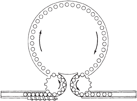
Rotary Fillers. The most common system for filling
containers are moderate to high speeds is rotary filling.
Containers arrive continuously on a conveyor and are
spaced by some means into a rotating infeed star that
delivers them, properly separated, to filling stations on the
main rotary assembly. The timing mechanism normally
employed to take containers coming at random to the filler
is a feed screw; for large containers and low-speed opera-
tion, timing fingers, escapement wheels, or like devices
may be used. The discharge from the main rotary is
usually by means of a second star wheel with the same
diameter as the first. However, if the liquid level is high in
the container, either a large-diameter star or a tangential
conveyor should be used to prevent spill.
On rotary fillers, valve utilization is almost indepen-
dent of container size but is a function of filler diameter.
For example, a 22-in. (56-cm)-pitch-diameter gravity filler
for 32-oz (946-mL) containers has a valve utilization of
49%, whereas a similar gravity filler having the valves on
a 60-in. (152-cm) pitch diameter has a valve use of 73%.
The time that the valve is closed is necessary for the
transfer of containers into and out of the rotary section
and for the relative movement between container and
filling valve needed to open and close the valve.
The concept of dual-lane rotary fillers, involving two
lanes (inner and outer) on the main rotary, was proposed
and patented many years ago. Except, perhaps, for large-
diameter carbonated-beverage fillers, the system is not
practical. Two infeed stars and two discharge stars (or a
tangential system) would be needed, and such an arrange-
ment greatly reduces valve use. The fact that valve
spacing is limited in the inner row is a disadvantage as
well, unless unequal production speeds are desired. In one
configuration study, the valve use on an 80-valve, dual-
lane, 60-in. (152-cm)-outer-lane-pitch-diameter machine
is
only 66%, compared
with the normal 85% use of a 48-
valve, 60-in. (152-cm)-pitch-diameter filler. Adding 67% in
number of valves adds only 29% to the production
capability.
Continuous-motion in-line fillers use a timing screw to
position the containers under multiple filling heads, which
move in synchronization with the containers.
Multihead in-line weight fillers may have a conveyor
system that separates and stops a group of containers.
Weighing platforms then lift the containers above the
conveyor for the filling cycle. Alternatively, they may use
452 FILLING MACHINERY, LIQUID, STILL
a lateral transfer device to place the containers on the
scale platforms.
Relative Motion. The relative motion between the con-
tainer and the liquid-dispensing device can significantly
affect filler performance. The various relative motions
possible are none, raise container, lower valve, and raise
container and lower valve.
In sealed-container filling (see Table 1), relative motion
between the container and the valve is required to bring
the valve into contact with the container. With manual
container placement, the container can be raised against
the valve, or the valve(s) can be lowered to one or more
containers on platforms.
The valve use of rotary sealed-container fillers can be
increased by lowering the valve (see Figure 7). With a
descending valve, the valve can begin to enter the con-
tainer at position 1, and it must be clear of the container at
position 1u. If the container is to be raised up to the valve,
the rise may not begin until position 2 because space must
be allowed for the container platform to clear the infeed
star. Likewise, the container platform must be in the full-
down position by position 2u. As an example, with 40
valves on a 60-in. (152-mm) pitch diameter, arc 1–1u is
327, whereas arc 2–2u is 306. This 6% difference may be
advantageous, but movement of each valve imposes other
difficulties on filler design, often including the need for a
flexible liquid connection to each valve. Such flexible
connections often make cleaning more difficult. The com-
bination of raising the container and lowering the filling
valve is very rarely used, as it requires mechanisms for
moving both elements, with all the disadvantages of each
system.
In-line, sealed-container fillers are rather slow and not
common, except for filling containers in a case. Most of
those available operate by lowering the valves to the
container, which permits the containers to remain on the
conveyor. As with sealed-container fillers, level-sensing
fillers require relative motion between the filling valves
and the container. Rotary level-sensing fillers typically
raise the container; in-line fillers bring the nozzle down to
the package.
Volumetric, weight, and time-fill fillers do not require
relative motion between the dispensing nozzle and the
package. Thus, for simplicity and economy, most of these
fillers operate with the nozzle located above the container
opening. However, two principal exceptions are as follows:
1. In filling containers with relatively small openings,
such as long-neck plastic bottles, greatly increased
rates of flow are possible if the product flow emerges
from the side of the tube and is directed against the
container wall (see Figure 1). Filling straight down
into that style of container from above may cause air
entrapment with consequent possible splashout or
overflow at the end of the filling cycle. The lost time,
if any, required to raise the container or lower the
filling valve may be more than offset by the faster
flow rates possible.
2. Viscous products such as mayonnaise and peanut
butter are best filled volumetrically using a flow
tube open at the bottom. To prevent air entrapment,
the flow tube is maintained at a position very close to
the rising surface of the liquid by lowering the
container during the filling cycle.
CONSIDERATIONS IN DESIGN AND SELECTION
OF FILLERS
Many factors must be considered in selecting filling
machinery. These include such obvious factors as operat-
ing and maintenance costs, efficiency, reliability, size,
speed, and materials of construction. Several considera-
tions, discussed below, are specific to liquid-filling machin-
ery and important to the satisfactory operation and use of
such equipment.
Accuracy. The accuracy of fill is important for two
reasons: (a) it is necessary to comply with state or other
regulations as to labeled content [the regulatory agencies
generally refer to the filling tolerances recommended in
the National Bureau of Standards Handbook 44 (2)] and
(b) in addition to meeting legal requirements, however,
packagers of most products desire to keep overfill to a
minimum, thus minimizing product giveaway. Even with
relatively inexpensive products, the amount given away
with inaccurate overfilling on high-speed production lines
can usually justify the higher cost of purchasing more
accurate fillers.
Changeover and Cleaning. As a part of operating costs,
the time and labor required for cleaning and preparing the
filler for daily operation, changeover from one product to
another or one container to another, and cleanup at the
end of each day’s production should be carefully evaluated.
User needs may range from fillers that operate 24 h per
day with no need for product or container-size change, to
fillers
for 30-min production
runs, after which the filler
must be completely sterilized and adjusted for a different
container size. Comments are made above concerning the
Figure 7. Rotary-filler arrangement.
FILLING MACHINERY, LIQUID, STILL 453
influence of filling techniques. The manufacturer’s de-
scriptions of container-positioning methods contain com-
ments on cleanability, container-size flexibility, and ease of
adjustment. Specific aspects of each filler design must be
carefully considered in choosing the proper liquid filler for
a particular application.
No-Container/No-Fill System. In general, it is desirable
to have a filler equipped with some type of no-container/
no-fill system. In most sealed-container fillers, the filling-
valve mechanism is designed to automatically provide a
no-container/no-fill system in conjunction with the action
of the container and the filling valve coming together.
Likewise, with most of the unsealed-container filling
techniques, a relatively simple container-detection device
can be used to prevent product flow if no container is
present. The constant-volume time filler does not permit
start or stop of product flow, but means such as drains in
the container platform to catch the product flow may be
provided. Alternatively, particularly on in-line fillers, a
control system may be provided to ensure that a full row of
containers is present.
Drive Location. The location of the main drive for the
filler should be considered in filler selection. Usually, the
main motor drive, or, alternatively, a lineshaft synchroni-
zation system, is located near floor level. Thus, the heavy
drive components are conveniently supported and reason-
ably accessible for routine maintenance. Because the
splash of corrosive products may significantly harm drive
components even if they are protected against splash,
some filler manufacturers locate the main drive above
the product. This may not be desirable for filling food or
drug products because of the potential for product con-
tamination from drive lubricants.
Equipment Standards. Various industry-consensus stan-
dards are applicable in the United States:
ANSI B155.1-1994 Safety Requirements for the Construction,
Care, and Use of Packaging and
Packaging-related Converting Machinery,
American National Standards Institute
3-A Sanitary
Standard 17-06
3-A Sanitary Standards for Fillers and
Sealers of Single Service Containers for
Milk and Fluid Mild Products,
International Association of Milk, Food,
and Environmental Sanitarians; U.S.
Public Health Service; The Dairy Industry
Committee
The first standard is general but applicable to fillers.
The 3-A Standard is specifically for milk fillers.
The packaging of certain products is regulated by
government agencies. The packaging of fluid-milk pro-
ducts in the United States is usually regulated by local
(i.e., county or state) authorities. They normally adopt the
3-A Standards without modification, but a few jurisdic-
tions impose their own requirements, usually stricter. If
fresh milk is packaged in flexible plastic containers, then
the container is usually the legally specified measuring
device. In such cases, volumetric tolerances normally
follow the recommendation of the National Bureau of
Standards (2).
The packaging of liquids in meat and poultry establish-
ments subject to inspection by the United States Depart-
ment of Agriculture (USDA) Food Safety and Inspection
Service is governed by guidelines issued by the depart-
ment (3, 4). Equipment for packaging food and drug
products is regulated in the United States by the Food
and Drug Administration (FDA) (CFR Title 21, Chapter I),
and the packaging of distilled spirits by the Bureau of
Alcohol, Tobacco, and Firearms (BATF).
BIBLIOGRAPHY
1. The PMMI 1994–1995 Packaging Machinery Directory, Packa-
ging Machinery Manufacturers Institute, Washington, DC,
1994.
2. Specifications, Tolerances, and Other Technical Requirements
for Weighing and Measuring Devices, National Bureau of
Standards Handbook 44, NBS, U.S. Department of Commerce,
Washington, DC, 1987.
3. Accepted Meat and Poultry Equipment, Meat and Poultry
Inspection Technical Services, Food Safety and Inspection
Service, U.S. Department of Agriculture, Washington, DC,
May 1984, pp. 1–8.
4. Guidelines for Aseptic Processing and Packaging Systems in
Meat and Poultry Plants, Meat and Poultry Inspection Tech-
nical Services, Food Safety and Inspection Service, U.S. De-
partment of Agriculture, Washington, DC, June 1984.
General Reference
C. G. Davis, Product Filling, Vol 1. of Packaging Machinery
Operations, Packaging Machinery Manufacturers Institute,
Washington, DC, 1987.
FILM, CERAMIC COATED
NOE OBINATA
Toppan Printing Company
For food packaging, gas/moisture barrier property is one of
the key elements to provide longer shelf life of products.
Aluminum foils, aluminum-metalized films, PVDC-coated
films, or coextruded EVOH films have played major roles
in barrier packaging. However, there are increasing de-
mands for more sophisticated packaging, such as trans-
parency, metal detector capability, microwaveability,
retortability, and environmental friendliness as well as
barrier properties. Ceramic-coated films are capable of
meeting the demands and have become more and more
popular recently.
Ceramic-coated films are AlOx- or SiOx-coated films of
excellent barrier properties, having the potentially of
reaching almost the same levels of O
2
and H
2
O barrier
454 FILM, CERAMIC COATED
as aluminum foil (Figure 1). Besides barrier properties,
transparency is another important aspect of these films.
Although the SiO
x
layer is somewhat yellowish, both the
AlO
x
and SiO
x
layers are clear, providing the marketing
advantage of allowing the consumer to see the product
inside the package and the quality control advantage of
more reliable visual inspection. These films also have the
advantages of metal detector capability and microwave-
ability. Unlike aluminum foil or metalized films, these
metal-free films allow metal detectors to work properly
and do not cause arcing in the microwave oven. Recent
improvement also imparts these films with the exciting
advantage of being retortable, with the durability to with-
stand the severe temperature and pressure conditions in
the retorting process. In the past, only metal cans, glass
containers, and aluminum–plastic pouches were retorta-
ble. Replacing the heavier and more bulky metal cans and
glass containers with packages made of ceramic-coated
films can result in significant cost /energy savings in
transportation and waste reduction. A comparison of
ceramic-coated films and other barrier films is shown in
Table 1.
A physical vapor deposition process is typically used
to form ceramic coatings. Figure 2 is an example of an
AlO
x
coating process. Aluminum is evaporated from a
crucible tank by electron beam heating and then reacts
with oxygen to form a thin layer of AlO
x
onto a substrate.
The process is done under high vacuum conditions to
achieve efficient evaporation and deposition of the
material.
Good Poor
Poor
Good
EVOH
OTR
Metallized PET
PVDC-coated OPP
PVDC-coated PET
Ceramic-coated films
Al Foil
WVTR
Figure 1. Oxygen and water vapor barrier map of typical barrier
films (1).
Table 1. Comparison Between Ceramic-coated and the Other Barrier Films, where
, W, and are Excellent, Moderate,
and Poor, Respectively
Films
Moisture
Barrier
Oxygen
Barrier Transparency
Use of Metal
Detector
Use of Microwave
Oven
Retort
Treatment
Ceramic-coated
Aluminum foil
Aluminum-metalized
EVOH
W
PVDC-coated WW
Al
unwinder
rewinder
electron beam
irradiation device
crucible tank
coating
drum
tension roller
spreader roller
oxygen
electron beam
vaporized
aluminum
Figure 2. An example of an AlO
x
coating process.
FILM, CERAMIC COATED 455
Since its commercial introduction in 1989, the Toppan’s
GL films (ceramic-coated films with SiO
x
or AlO
x
coating)
have been a family of leading transparent barrier films for
food packaging applications. Later in 2002, the Toppan’s
GX films were introduced to provide higher gas barrier
(Table 2). The collection of the GL and GX films now
provides (a) the gas/moisture/aroma barrier, (b) transpar-
ency, (c) printability, (d) capability of microwave ovens and
metal detectors, (e) retortability, and (f) environmental
friendliness suitable for a wide range of food packaging
applications. The GL/GX films have been used for more
than 200 food and pharmaceutical products (Figure 3).
Driven by the demand for high-barrier transparent
films, ceramic films have become increasingly accepted
by packaging suppliers. Some major suppliers and their
products are listed in Table 3. Most of the products
are available in the United States and Europe. The
Mitsubishi’s Techbarrier
s
uses PVA as a base film for
high oxygen barrier, but extra care must be taken against
moisture absorption under humid conditions. The Toyobo’s
Ecosyar
s
uses the two-component process of AlO
x
and
SiO
x
simultaneous coating. According to the supplier’s
catalogue, the two-component process could provide both
advantages of AlO
x
and SiO
x
, meaning that high density
and good barrier are from AlO
x
while flexibility and high
impact strength are from SiO
x
.
Usage of ceramic-coated films has steadily increased in
recent years. Their versatile characteristics meet chan-
ging demands of food packaging, such as higher barrier,
visibility inside the package, and retortability. In particu-
lar, retort applications will support expansion of using
ceramic-coated films as consumption of retort-pouched
food has increased on a world basis. The major market
for ceramic-coated films is in food packaging applications;
however, a recent trend suggests that the applications of
these films for pharmaceutical and electronic products
could rise in the next future, although more improvement
of the films may need to be made.
BIBLIOGRAPHY
1. Worldpak 2002, Proceedings of the 13th IAPRI Conference,
2002, CRC Press LLC, Boca Raton, FL, 2002, p. 410.
2. Functional material, Vol. 27, No. 3, p. 53 (2007).
Table 3. Major Suppliers of Ceramic-Coated Films and Their Products
Suppliers Products Barrier Materials Base Films
Toppan Printing GL, GX Films AlO
x
, SiO
x
PET, PA
Toray Barrialox AlO
x
PET
Dai Nippon Printing IB-Film AlO
x
, SiO
x
PET, PA
Mitsubishi Plastics Techbarrier
s
SiO
x
PET, PA, PVA
Toyobo Ecosyar
s
AlO
x
and SiO
x
(two-component process) PET
Alcan Ceramis SiO
x
PET, PA
Figure 3. Example of food packaging applica-
tions using GL/GX films.
Table 2. Barrier Properties of GL/GX Films
a
(2)
Film O
2
TR
b
(cm
3
/m
2
/day/MPa) WVTR (g/m
2
/day)
GX 2.0 0.05
GL-AE 5.0 0.6
a
Films are laminated with LLDPE (60 mm).
b
O
2
TR measured at 301C and 70%RH, WVTR measured at 401C and
90%RH.
456 FILM, CERAMIC COATED
FILM, EDIBLE
JOHN M. KROCHTA
Food Science and Technology,
UC Davis, University of
California, Davis, Davis,
California
DEFINITION AND FUNCTIONS
Edible films are stand-alone structures that have appear-
ance and protective functions similar to synthetic polymer
films. However, they are comprised of edible proteins,
polysaccharides, lipids and/or resins, and other compo-
nents that render them edible. Thus, they can be con-
sumed with a packaged product, resulting in less
packaging that requires disposal. Also, since edible films
are made from renewable resources, they contribute to
package sustainability.
Edible films by convention have thicknesses r10 mil
(r254 mm), above which they would be considered sheets.
They can be used as food wraps, and some can be formed
as food casings or can be heat-sealed into pouches for food
products. Edible films can also be formed as coatings
directly on the surfaces of food and pharmaceutical pro-
ducts, thus becoming a part of the product.
Present uses of edible films include collagen casings on
sausages to inhibit moisture loss and oxygen transport
and provide structural integrity; hydroxypropylmethyl
cellulose (HPMC) pouches for premeasured food and
beverage ingredients; gelatin capsules for pharmaceuti-
cals to improve product appearance, structural integrity,
ingestibility and stability; and dissolvable breath strips
made from a number of different edible materials. Present
uses of edible films as coatings include shellac and wax
coatings on fruits and vegetables to prevent moisture loss
and improve appearance; methyl cellulose (MC) and
HPMC coatings on fried foods to reduce fat update;
shellac, wax, and zein coatings on confections and drug
tablets to provide moisture resistance and improve ap-
pearance; and MC and HPMC coatings on drug tablets to
improve product stability appearance and ingestibility.
Edible films and coatings are generally seen as having
considerable potential for applications far beyond present
uses for improving product quality and safety. In addition
to controlling moisture, oxygen, aroma, and/or oil transport
and protecting products from mechanical forces, edible
films and coatings can act as carriers for edible antioxi-
dants, antimicrobials, and other additives. Furthermore,
edible films can be positioned within food products as
separation layers to reduce migration of moisture, lipids,
and solutes from one food component to another.
In some instances, edible films and coatings have poten-
tial for reducing use of synthetic packaging films. However,
they are not intended to eliminate the need for nonedible
protective packaging. Rather, they are intended to work
with conventional packaging to improve product quality
and shelf life. To the degree that an edible-film wrap, casing,
pouch, capsule, or coating functions to protect the product
from the environment, the amount and complexity of
nonedible protective packaging can be reduced, leading to
source reduction and improved recyclability. For example,
an edible pouch for premeasured dry milk powders used in
bakeries may only need a recyclable paperboard box as a
secondary package. Or, an edible oxyen-barrier coating on
roasted peanuts could eliminate the requirment for an
oxygen-barrier layer in a flexible pouch, resulting in a
single-layer moisture-barrier package that is more easily
recycled. In addition, after packaging is opened, an edible
coating can continue to protect the product.
The objective of this article is to review the materials,
manufacture, properties, applications, and trends of edible
films. The area of microencapsulation of food and drug
ingredients is not covered.
FILM COMPOSITION
Components of edible films must meet the same rigorous
standards applied to all food ingredients. Materials used in
formation of edible fims must be generally recognized as
safe (GRAS) for intended use or sanctioned by the U.S. FDA
Code of Federal Regulations or the U.S. Pharmacopoeia/
National Formulary (or equivalent). It is also necessary
that all edible film components be included on the product
label, to provide information critical to consumers with
allergies or intolerances to particular food components.
Film Formers
Film-forming materials available for edible films fall gen-
erally into the categories of polysaccharides, proteins,
lipids, and resins derived from plants and animals. Pro-
tein film formers include collagen, gelatin, casein, whey
protein, corn zein, wheat gluten, and soy protein (1–4).
Polysaccharide film-forming materials include cellulose
derivatives, starch and starch derivatives, carrageenan,
alginate, pectinate, and chitosan (5, 6). Layering and
blending of proteins and polysaccarides show potential
for optimizing film properties (7–9). Films can also be
produced from purees of foods such as fruits and vegeta-
bles, which contain combinations of ingredients (10). The
polar hydrogen-bonding character of polysaccharides and
proteins produces films that have (a) high moisture per-
meability, (b) low oxygen and lipid permeabilities at lower
relative humidities, and (c) compromised barrier and
mechanical properties at higher relative humidities. Ed-
ible lipids and resins include carnauba wax, candelilla
wax, beeswax, triglycerides (e.g., milkfat fractions), acety-
lated monoglycerides, fatty acids, fatty alcohols, sucrose
fatty-acid esters and shellac (11–15). Lipid and resin
materials are not polymers and, therefore, do not gener-
ally
form coherent stand-alone
films. However, they can
provide gloss and/or moisture-barrier coatings on food or
drug surfaces, or they can constitute the moisture-barrier
component of a composite film. Composite films can con-
sist of either (a) a lipid layer supported by a polysacchar-
ide or protein layer or (b) lipid material dispersed in a
polysaccharide or protein matrix (16, 17).
Materials used for edible films also have potential
for replacing synthetic polymers in some nonedible
FILM, EDIBLE 457