Yam, Kit L. (ed.). The Wiley encyclopedia of packaging technology
Подождите немного. Документ загружается.

Three-piece can manufacture is readily adaptable to
making cans of any diameter and height. The production
equipment is amendable to changes in size and is capable
of production speeds of up 700+ cans per minute when
cans are made as singles. In case of multi-high canmaking,
the bodies are scored to final individual height prior to
rolling and welding; subsequently separated outputs of
1200 to 1500 cans per minute are achieved on appropri-
ately designed lines. Where the use of lead/tin solder is no
longer acceptable, the change to welding can be made at
minimal cost on existing lines, because only the equip-
ment that makes the cylinder (the bodymaker) needs to be
changed.
Three-piece manufacture is the choice of the small-to-
medium-sized operation requiring flexibility for producing
can sizes required in relatively modest quantities or
to suit a variety of fill products that require changes
in coating specifications. This is the salient asset of
three-piece canmaking facilities. It allows the manufac-
ture of various can types, i.e., food, flat and/or carbonated
beverages, aerosols, and general line cans (industrial and
dry products) by adding the adequate complementing
equipment at limited cost to the existing line as long as
the bodymaker can cope with the range of cans to be made.
Two-piece can manufacture is basically suited to a
single can size, which requires outputs of at least 150 to
300 million cans per year. Yearly productions of modern
lines are usually much higher, i.e., in the range of 400 to
500 million per annum. DRD, using precoated sheet or coil
material, is used for food cans and predominently in the
shallower sizes (h/do1). The process is being used, how-
ever, for food cans with an h/d ratio of 1.5 in the popular 3-
in. (7.6 cm) diameter, e.g., 300 406 in the United States
(for explanation of can dimensions: The first digit stands
for inches and the two last ones, for sixteenths of inches;
the measures are taken on the finished can overall in
length and over the double seems in diameter).
The application of enamel to both sides permits the use
of electrolytically chromium coated steel (ECCS), which
has a surface that is too abrasive to be used uncoated
(plain). It does also not offer any corrosion resistance.
Because economics demand the use of the thinnest possi-
ble can stock, the high strength needed dictates the use of
double-reduced (DR) grades. Additional strength is pro-
vided by beading or reforming the can bodies and adapting
the profiles of the ends for increased flexibility in the
autoclave, i.e., providing a maximum of expansion volume.
Generally, using two presses with a minimum of per-
ipheral equipment, DRD provides a compact installation
of relatively low capital cost for the achievable outputs.
For that reason, it seems to be a preferred method for self-
manufacture (captive canmaking) of relatively shallow
containers by packers (e.g., tuna fish cans). However, the
material property requirements and its constance of
drawability are high, and the standard of enameling is
critical to maintain integrity as the metal is formed.
D&I converts a plain coil into a fully finished can in a
totally integrated, fully automatic process. The high capi-
tal cost of the full range of equipment needed implies
a high volume in a nonfluctuating and constant ensured
market. Together with the desirability of keeping the line
running once harmonious operation has been achieved,
this results in a 24-hour per day, 7-day per week operation
with annual production up to planned business feasibility
studies. Basically a single-can-size process, it is best
suited for the production of beverage cans, which are
made worldwide in a few standard sizes for use of high-
speed filling-closing lines. D&I thin-walled cans are pres-
sure packs (4 to 6 kg/cm
2
constant pressure in carbonated
drinks cans and much higher in D&I aerosol cans).
Their rigidity derives from the high inside pressure.
Such pressures are currently generated in noncarbonated
fills by inoculating a specific quantity of liquid nitrogen
into the headspace of the filled cans just prior to closing
the cans. This offers more and vast opportunities for light-
weight two-piece D&I cans.
Either tinplate or aluminum is used, usually on a
dedicated line. In recent years, because of the uncertain
economics relating to metal costs, new lines are built as
‘‘swing lines,’’ which basically can handle either metal. It
does nevertheless require some downtime to make the
change over, and lines normally operate continuously on
the one metal.
THREE-PIECE CAN MANUFACTURE
The manufacturing process of three-piece cans is as
follows: cut up coil stock into rectangular sheets; coat
and/or decorate sheets; slit into rectangular blanks; form
cylinders and side seam (soldered or nonsoldered, or
welded side seams); inside and/or outside side seam strip-
ing (lacquer or powder application and curing); separate
cylinders in case of multi-high cylinders; neck and or bead
if appropriate; expand or reshape or reform cylinders if
appropriate; form flanges at both extremities; fit maker’s
end; organized visual inspection or/and automatic leak
testing; and casing or palletizing (see Figure 3).
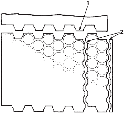
Figure 2. Scrolled sheet showing layout of blanks and scrolled
edges for material utilization. 1, Primary scrolling used when
cutting coil into sheets for coating. 2, Secondary scrolling used for
cutting sheets into strips for feeding into the shell press.
728 METAL CANS, FABRICATION
Cans for corrosive or delicate products (carbonated
beverages or red fruit, etc.) are internally spray coated
and cured prior to applying the maker’s end. This coat is
called ‘‘top coat,’’ whereas the ‘‘bottom coat’’ is applied on
the flat sheet in roller coaters and cured in wicket ovens.
Both bottom and top coats can be spray coats with or
without intermediate curing (spray–spray–cure or spray–
cure–spray–cure).
Slitting. Large rectangular sheets of can body stock,
precoated if required on one or both sides by roller coating
techniques, are slit by pairs of circular knives (3) on
tandem slitters, first logitudinally into strips in which
the width corresponds with the development of the can
bodies, and then transversely into rectangular blanks of
the appropriate size corresponding with the can height,
respectively, with the allowance to form the welding over-
lap (or the lock side seam in case lap-locked side seamed
cans are made, soldered, or nonsoldered or cemented).
Because welded cans have considerably less overlap
(0.4 to 0.8 mm) at the side seam than soldered cans (side
seam allowance), slitting demands more rigorous preci-
sion (dimensions and right angles) than is needed for
soldered can blanks. Circular slitting cutters can be posi-
tioned accurately by applying internal pressure at the
bore of the cutter hubs to expand them so as to move freely
on the slitter shaft (4). The said hubs can also be blocked
on the shafts by screw jammed wedges or by application of
hydraulic pressure (compressed grease) inside the hub.
Any of these proven methods must apply the needed
jamming pressure perfectly symetrically to avoid distort-
ing the setting (narrow slitting gap, usually 5% of the body
stock thickness) or/and cause wabbling of the slitter
knives’ cutting edges.
Bodymaking, Soldered Cans. The solder alloys com-
monly used consist of 98% lead and 2% tin. As more and
more countries impose lower limits of lead content in food,
the soldered can is being phased out in Western countries,
if not being banned altogether as in the United States.
Nevertheless, many soldering lines around the world will
continue in operation for some time. The machine consists
of a ‘‘bodymaker,’’ which feeds single blanks from the feed
hopper, and then scores (in case of multi-high can bodies),
flexes, and forms the blanks into cylinders after slit and
clip notching and hooking. The bodymaker is coupled to
the side seamer, i.e., the soldering attachment where the
joint is soldered and wiped off the excess of solder accu-
mulated at the outside of the side seam.
Blanks are still commonly transferred manually from
the slitter blank collector, although equipment exists for
automatic transfer. In the first case, a visual check for
quality and eventual rejects is possible, whereas sophisti-
cated devices check automatically any miscut blanks
and trigger the programmed intervention. The prepared
hooks, or edges, as prepared and formed in the hooking
station(s) of the bodymaker are interlocked on the forming
horn and are compressed in the horn spline groove by the
bumping steel. For high-speed operation, the body cylin-
der is usually formed by a pair of wings. (The term ‘‘wing
form bodymaker’’ contrasts with ‘‘roll form bodymaker,’’
which is a former American Can Co. technique.) In this
technique, bodies are rolled and consecutively notched
and hooked in the rolled shape.) Liquid flux is applied
on one or both hooks prior to engage and bump the side-
seam on the forming horn.
The lap-lock assembled bodies are fed out of the body-
maker and picked up synchroneously and individually by
the clamping pawls of the soldering chain. The side seam
area is preheated by ribbon gas burners before passing
over a longitudinal solder roll where solder is applied. The
presolder ribbon burners preheat the side seam, and by
appropriate setting of the ‘‘bow and counter bow’’ burners
the side seam is kept as straight as possible. When
applying solder, post-solder ribbon burners ensure that
the solder is ‘‘sweat’’ into the capillary gaps of the side
seam, after which a rotating wiper mop removes excess
solder, mainly in the form of blobs. Any solder splashes
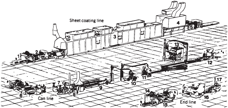
Figure 3. Three-piece can manufacture. Sheet-coating line: 1, sheet feeder; 2, roll coater; 3, oven; 4, cooler; and 5, unloader and sheet
stacker. Can line: 6, slitter; 7, blank feed; 8, bodymaker; 9, side seamer; 10, flanger; 11 beader; 12, end seamer; and 13, tester. End line: 14,
sheet feeder; 15, secondary scroll shears; 16, shell press; and 17, compound liner. Courtesy of Metal Box Ltd.
METAL CANS, FABRICATION 729
toward the inside of the can bodies have to be avoided.
Rotary solder splash shields provide for this.
The can is then cooled by air jets before conveying to
the downstream finishing operations. As lead contamina-
tion has become an increasing concern, the wiper mop
unit has been the subject of considerable improvement to
contain the lead dust generated by its operation, particu-
larly at high-speed canmaking operation. By its nature,
the process requires the use of tinplate, although black-
plate had been soldered during World War II in the United
States. To ensure sound soldering, a minimum ‘‘solder-
ability’’ has to be ensured: rugosity of the steel base, a
minimum of alloyed and free tin, oxidation, and so on. The
line operator’s skill and experience will overcome most of
the material inherent drawbacks, the major one of which
is the fluctuation of stiffness of the steel base of the blanks
(open or thick laps).
Bodymaking, Welded Cans. The side seam is made by a
resistance-welding process using the ‘‘lost-wire-electrode’’
principle (5) as well as The Canmaker June 1996 issue
Evolution of a bodymaker by Sigfried Frei, Frei AG
Switzerland. Body blanks are fed from the bottom of the
feed hopper and then transferred through double blank
detectors; then, the blanks are scored for eventual multi-
high can bodies and flexed into the forming rolls (See
Figure 4).
The two laps of the rounded cylinder are butted in the
grooves of the Z-bar, and the cylinders are pushed along
the Z-bar by one or more driven chains provided with
pawls. Upon perfect radial centering in the Z-bar, the
cylinders are introduced into the welding rolls at the same
speed as the said rolls are driven at. The actuating
mechanism of the reciprocating introduction pusher pawls
are designed so as to guarantee that pushing speeds are
accurately matching the peripheral roller electrodes
speed. Only the outer electrode is driven.
Overlap accuracy over the full length of the side seam,
which is also dependent on gauge and temper of the plate,
has to be controlled as to avoid bodymaker jams and
wrecks or mainly irregularly welded side seams. The two
overlapping edges of the cylinders are bonded by a-c
resistance continuous nugget welding using approxi-
mately 4000 to 7000 A at 8 to 5 V. Both overlapping edges
must be free of contamination, each one on both sides
(lacquer splashes or traces) to eliminate variations of
resistance, which would lead to welding faults as well as
eventual copper wire ruptures.
A significant amount of energy is lost in heating other
parts of the welder, such as welding arms and electrodes,
which need water cooling. In high humidity, this can lead
to problems with condensation. Thermostatically con-
trolled cooling media, even on upper acceptable limits of
operation temperature, should avoid reaching dew points.
Each resistance welding spot, which is called a nugget,
is achieved by one half of the a-c wave cycle. Welding
current supply to the electrodes and welding speed are
limited because the nuggets should overlap longitudinally
to ensure a homogenous side seam over the full length of
the side seam. To achieve higher welding speeds of up to
120th per minute, higher welding current frequencies
have to be generated via an alternator or static transfor-
mers. Other sinuosoidal waveforms are applied and
contribute to reaching high welding speeds coping with
different canstock surface conditions.
Earlier systems used a large overlap (2 to 3 mm) and
raised the steel temperature to the melting point by
applying welding roller pressure to forge weld the metal.
The latest welders use a small overlap as mentioned (0.4
to 0.8 mm) with metal temperatures just below the melt-
ing point and increased roll pressure to forge the two laps
together. To ensure reproducible welding conditions over
the full length of all double seams produced, the electrode
contact is made by endless copper wire wrapping around
both welding rolls and moving the cylinders at the preset
welding speed. Any contamination of the welding electro-
des by tin pick-up is thus continuously removed from the
contact area. After use on both sides of the profiled wire, it
is either chopped or rewound for recycling.
Having dealt effectively with the problem of tin con-
tamination of the copper wire electrodes, the system
paradoxically requires a minimum of tin coating on the
can stock, around 0.09 lb/bb on both sides (1.2 g/m
2
on one
side.) Table 1 shows the comparison of properties of
various materials wherein nr 25 and nr 10 stocks have
respectively tin coatings of 2.8 and 1 g/m
2
on one side. TFS
or ECCS materials, as well as blackplates, are poorly
weldable if at all under acceptable production conditions.
They have to be ‘‘edge cleaned,’’ i.e., the oxide films have to
be abrased from the four sides of the overlapping edges of
the side seam. Edge cleaning has, however, never found
reliable solutions apart from edge cleaning by ‘‘edge
milling’’ as practiced by the Continental Can Company
in their Conoweld Technique. This system used welding
rolls without an intermediate copper wire, but it is now of
less importance in high-speed canmaking, mainly because
of the frequent need for changing the electrode rolls.
The integrity and quality of the seam weld is usually
tested by visual and mechanical means (e.g., Ball test). For
a more detailed examination, weld cross and longitudinal
metallographic inspection will reveal any sign of separa-
tion between laps, cavities and so on. Radiographical
examinations are also used for quality inspections.
Welders have been fitted with ‘‘weld monitors’’ to monitor
welded seam quality continually. Usually, these monitors
rely on measurements of voltage or current fluctuations
between the welding electrodes. Welded seams, as well as
single nuggets, made outside the preset limits are de-
tected, and the faulty cans are ejected. Other monitoring
systems have been explored for enhanced performance
and were based on weld temperature or on the final
thickness of the forge-welded overlapped side seam.
Renewed effort went into welding the side seam by
means of a laser beam (6). The principle of can welding by
a laser was demonstrated in the late 1970s, but welding
speeds seemed to be too low to justify commercial exploi-
tation. The technique was then discarded. Positive results
of other ongoing research and development (R&D) work
on the subject in the United States, Europe, and Japan are
not known. Apart from the elimination of costly copper
wire, the method offers pure butt welding with advan-
tages to double seaming of the ends, necking, as well as
730 METAL CANS, FABRICATION
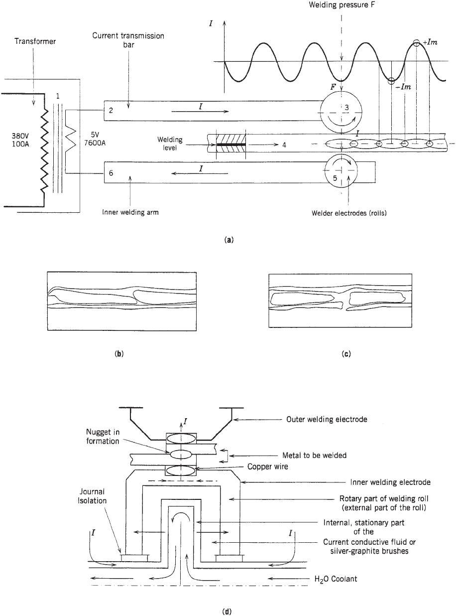
Figure 4. (a) Fundamentals of electric canbody welding. (b) Longitudinal section of a welded seam showing overlapping weld nuggets
(40 ). (c) Longitudinal section of a welded seam showing separated weld nuggets (40 ). (d) Section through elements involved directly at
the welding station.
METAL CANS, FABRICATION 731

versatile decoration such as wrap-around printing. The
copper-wire-welded seam and the plain welding margin in
case of lacquered insides of the cylinder interrupt an
otherwise smooth inside enameled (or plain) surface.
The welded seam contains exposed iron and iron oxide
as well as eventual traces of copper besides tin at either
side of the weld. To protect the product from contamina-
tion and/or the weld from attack by the product that still
results in contamination of the product, the side seam
needs to be coated in most cases.
The formation of iron oxide can be avoided by neutral
gas welding, in which case the weld area is isolated from
the atmosphere by neutral gas jets such as nitrogen and a
small percentage of hydrogen. This can be done at the
inside and/or at the outside of the side seam.
Bodymaking, Cemented Cans. Cans used only for dry or
otherwise neutral products, such as powders of specific
natures, mineral or/and vegetable oils as well as many
industrial products. Melted organic cements are injected
into the inner hook of lap-locked side seams and, after
engaging and flattening the side seam, they act as sea-
lents. Before the almost universal use of two-piece cans
for high-output beverage-can production, one method for
making them was to cover the longitudinal edges of the
blanks with a nylon strip, which was fused after forming
the cylinder. The process has a many of proprietary names
(eg, Miraseam and A-seam). An advantage was the com-
plete protection of the raw-cut edges of the blank. It could
only be used with precoated TFS, because the melting
point of tin is close to the fusion temperature of the plastic.
Even tapered corned beef cans were made in this way.
When tin prices were a multiple of the current ones, using
TFS was most cost-attractive solution. Cost cutting
in metal packagings is therefore not an exclusive pre-
sent-day problem. The bodymaker used to make the
nylon-bonded cans was an adaptation of the soldering
configuration.
Completing the Body. The plain cylinder must be furn-
ished with a flange at each extremity of the cylinder or
otherwise odd-shaped body for attachment of the closure.
For food processed in and with the can, where the can may
be subjected to external pressure especially at the cooling
phase of the autoclaving cycle, or remain under internal
vacuum during storage, the cylinder wall may be ribbed or
beaded for radial strength. Beading profiles and distribu-
tion along the can body are to be designed so as to reach
the desired proportion of radial against axial resistance of
the cans.
Cylinders for shallow containers, especially those that
cannot be made on bodymakers because of limited mini-
mum cylinder height, may be made ‘‘multi high,’’ i.e., in a
length suitable for two or three cans to obtain maximum
efficiency from the forming machine. The welding speed
remains unchanged thereby whereas the mechanical mo-
tions are divided by 2 or 3. Two techniques are used for
parting the multi-high bodies into their double or triple
components by breaking the score line or by cutting
peripherally the unscored bodies.
TWO-PIECE CAN MANUFACTURE
Metal Forming Methods. Both methods of making two-
piece cans use metal-forming principles that depend on
Table 1. Comparison of Properties of Various Materials
a
Properties
a
Material Section structure Weldability
Lacquer
adhesion
Iron Pickup Value
(IPV)
Filiform corrosion
(FFC)
LITEWEL-N Cr
ox
Cr
o
Sn
Ni-Sn-Fe
Base steel
#25 Tin plate Cr
ox
D
Sn
FeSn
2
Base steel
#10 Tin plate Cr
ox
DD
Sn
FeSn
2
Base steel
TFS Cr
ox
x
Cr
o
Base steel
Low-nickel-plated steel Cr
ox
D
Cr
o
Ni
2
Base steel
a
Excellent
Good D Normal x Poor Cr
ox
: Chromium oxide Cr
o
: Chromium metal
Source: NKK Technical Bulletin—The Steel Canstock Guide by Elizabeth Parr, Sheffield, UK.
732 METAL CANS, FABRICATION
the properties of metal to ‘‘flow’’ by rearrangement of the
crystal structure under the influence of compound stresses
without rupturing the metal.
Drawing. In drawing, as applied to can manufacture, a
flat sheet is formed into a cylinder or other section, such as
oblong, e.g., fish cans, by the action of a punch drawing it
through a circular or different shaped die. See Figure 5
showing the basic tool parts involved and the stresses and
strains occuring in the material. Some thickening toward
the upper part of the drawn element is inevitable, but the
process is essentially one of diameter reduction at constant
metal thickness and volume so that the surface area of the
drawn part is practically equal to the surface area of the
blank from which is has been formed. This factor forms the
basis of design, in particular the calculation of metal use.
The amount of diameter reduction achievable, i.e., from
blank to cup diameter, is governed by the properties of the
material, the surface friction interactions between the
tooling and the material influenced by the tool, and mate-
rial surface conditions and lubrication. The blankholder
force is an additional factor that adds to the drawing force
which the material has to stand between punch and draw
radii. Drawing has been the subject of much research. One
of the classic relationships is shown in Figure 6.
The diameter of the cup produced in the initial draw
may be reduced even more by a similar redraw operation
with a draw sleeve fitting between the punch and the
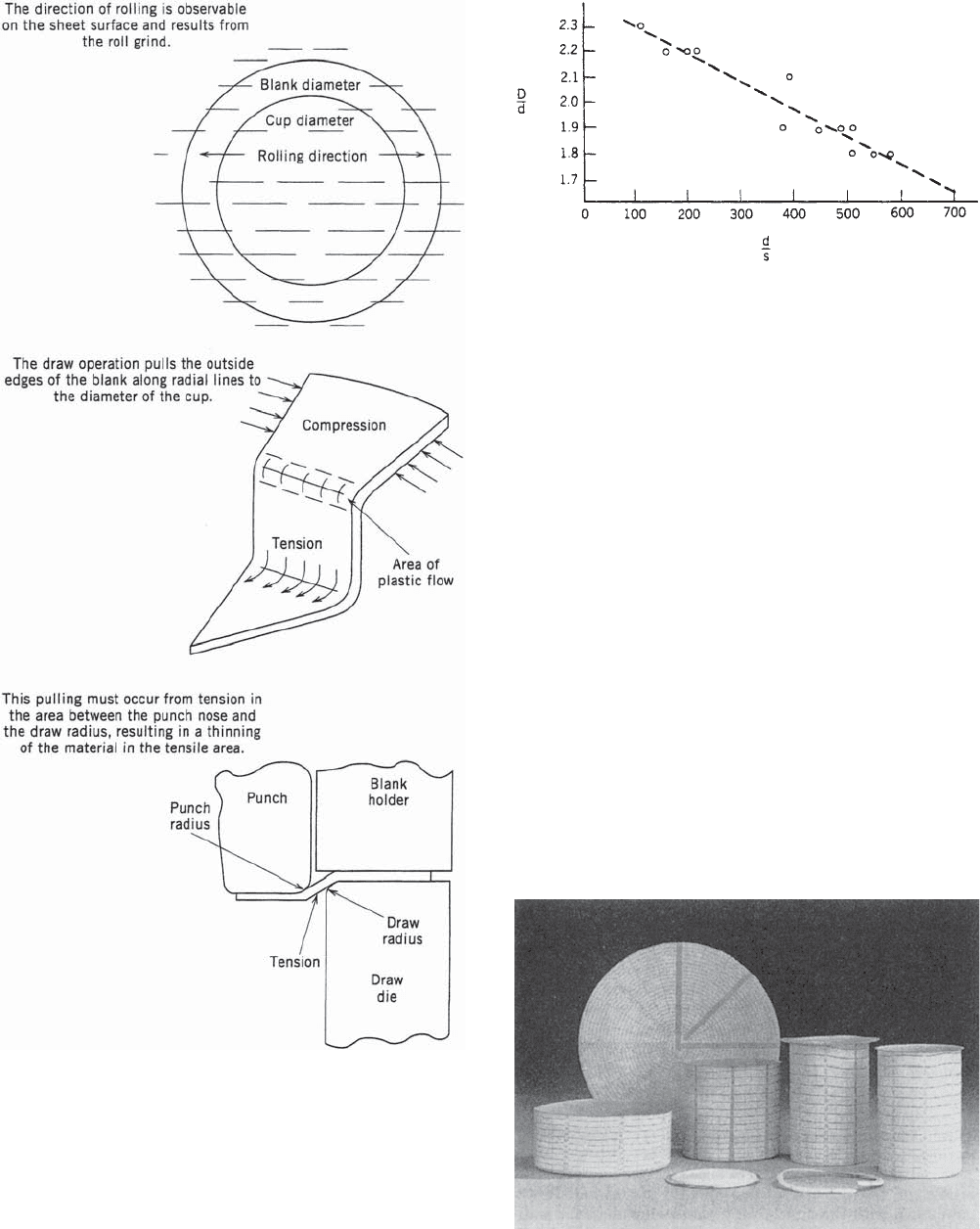
Figure 6. Limiting draw ratio. The maximum blank diameter
which can be drawn into a cup without metal failure. The
relationship illustrate the significance of sheet thickness (gauge).
D = blank diameter; d = punch diameter; s = sheet gauge. Courtesy
of International Tinplate Conference, 1976.
Figure 5. Basic stresses and strains. Courtesy of ALCOA Form-
ing Aluminum.
Figure 7. Reduction in diameter is accompanied by a corre-
sponding increase in height. Courtesy of Styner O Bienz, Nieder
Wangen/Bern Switzerland.
METAL CANS, FABRICATION 733
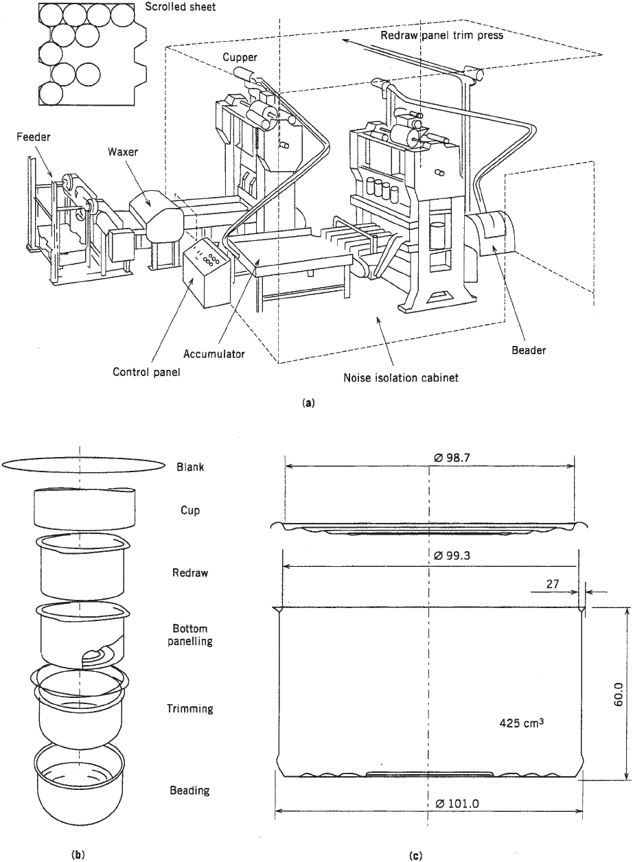
Figure 8. (a) Typical lay out of medium production of DRD cans. Courtesy of Ferembal Nancy/France. (b) Sequence of DRD fabrication
steps (c) Typical 401 206 DRD can with end (for ref. only).
734 METAL CANS, FABRICATION
inside diameter of the cup. The said draw sleeve acts as a
blankholder. The rule of constant area and volume deter-
mines that the reduction in diameter is accompanied
by a corresponding increase in height (see Figure 7). The
redraw operation can be repeated in several drawing
stages, provided the progressive reductions fall between
definite limits to avoid metal failure. Draws can be made
‘‘through the die,’’ and the drawn part be stripped from the
punch at the end of the press stroke below the die or the
press stroke can be limited so as to leave the drawn part
with a flange. In this case, the drawn part is extracted
from the die and is retained by the punch (friction and
vacuum), and ultimately it is stripped from the punch for
transfer or evacuating from the press. The stroke of the
press has to be adapted accordingly. In the latter case, it is
usually equal to 2.5 times the cylinder height as drawn.
Figure 8(c) shows a typical drawn can provided with a
stacking or/and label retaining bead if canstock is not
decorated. Figure 8(b) is the sequence of operations from
the blank to the finished can, and Figure 8(a) is a typical
schematic layout of a DRD can production line of medium
production capacity.
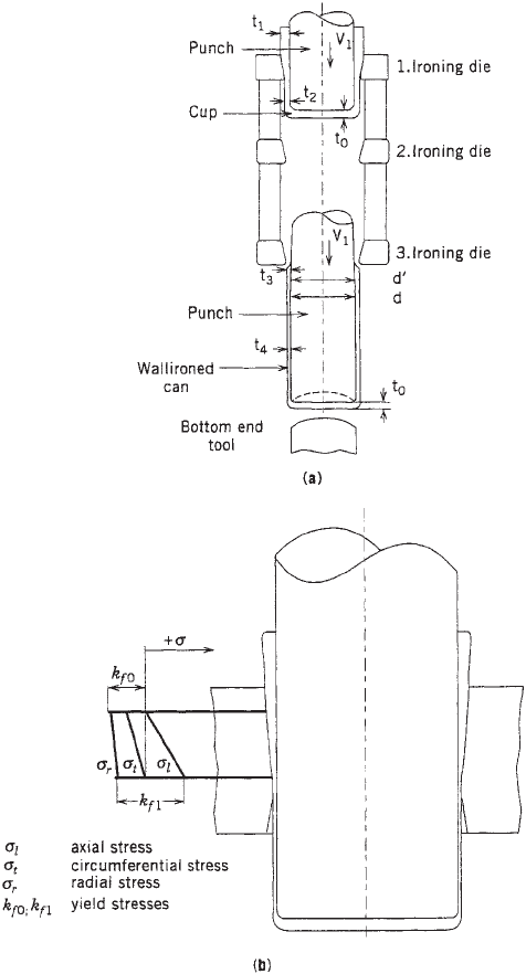
Wall Ironing. In pure ironing, as used in the D&I
process, a cylindrically drawn cup is redrawn by the
ironing punch and therefore precisely fits the said punch
diameter. The redrawn cup is then forced axially through
a set of ironing die rings, whose diameters, which are
progressively decreasing, create a gap with the punch that
is smaller than the wall thicknesses of the redrawn cup
and the consecutive wall thicknesses from t1 to t4; see
Figure 9(a) whereon the stated wall thicknesses are
related with the punch and rings radii differences.
The process, which is similar to impact extrusion, thus
results in a reduction in wall thicknesses at a constant
diameter excepted for t3 where the punch diameter is
recessed so as to form the ‘‘thick wall.’’ t4 is the ‘‘thin wall’’
that is reduced from 0.22 mm for t0 down to 0.07 mm. Here
too, the governing principle is the constant metal volume.
In other words, the volume of the metal in the ironed can
body (prior to trimming) is equal to the ingoing cup
and consequently to the original blanked disk. Note the
sequence of operations in Figure 10. The amount of
reduction at each stage is determined by the material
properties, governed by the needs to avoid metal failure.
The high friction, under extreme surface pressure mainly
at the outer surface of the ironed can body, makes special
demands during lubrication, which is combined with
copious flood cooling to maintain the critical punch-to-
die gap.
A similar effect can be obtained in drawing if the gap
between the draw die and the punch is less than that of
the metal being drawn. It is common practice to keep this
gap equal to the nominal thickness of the canstock to
control thickening caused by diameter reduction. This
process is called sizing. The drawing gap can be reduced
even more to produce a definite thinning of the wall,
relative to the base material as a combination of drawing
and ironing, or thinning. Special lacquering is primordial
in this case.
D&I Can Manufacturing. The procedure of producing
D&I cans is schematically as follows: unwind the plain
coil; lubricate; conduct blanking and cup drawing; redraw;
execute wall ironing; perform dome forming; trim body to
correct height; wash and surface treat (if appropriate as
for aluminum); implement dry or wash coat; and cure.
Then for beverage cans, the process is as follows: base coat
outside and cure (if appropriate; decorate and cure); coat
inside and cure (eventually a double coat); and neck and
flange open end (in the case of a tinplate, the order of the
last two operations may be reversed). For food cans, the
process is as follows: wash coat outside; neck and/or flange
as appropriate and if body is not beaded; body beading;
and coat inside (in some lines the order of the two last
Figure 9. (a) Schematic of wall ironing principal Courtesy of:
Tin-plate and modern canmaking technology by E. Morgan (b)
Ironing DWI can body and stresses on the material. Courtesy of
Rasselstein AG Germany.
METAL CANS, FABRICATION 735
operations is reversed). The closures,orends, are made
from precoated sheets or coil on multi-die presses, which
are profiled in such a way that internal pressure will not
cause any permanent deformation (peaking) in the chuck
wall radius area. Their turned down edge of the flange
(crown shaped or plain) is curled so as to allow stacking
and automatic handling and assist the formation of the
double seam. A sealing compound is nozzle injected onto
the spinning ends and then placed and centrifuged so as to
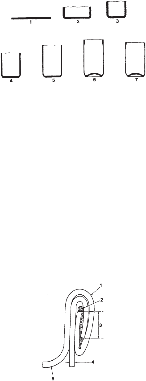
form a gasket in the finished double seam (see Figure 11).
Compounds are either solvent based (hexane) or water
based, which are, respectively, drying by evaporation
of the solvent or by heat drying (hot air or various
radiations).
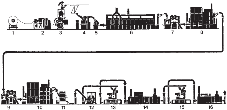
The components of a D&I line are shown in Figure 12.
The coils are shipped with the axis vertical, for safety and
to avoid damage to the laps. A down ender is used to bring
the axis horizontal and to transfer the coil to a coil car for
distribution to one of several dereelers (unwind stands),
each feeding one cupping press or cupper. Dereelers may
be dual and engineered in such a way that coil changes are
rapid either when coils are finished or if one has to be
removed for being defective. The coil is passed through a
lubricator where lubricant is applied by dipping in a tank;
the excess is removed in a couple of rubber-covered rolls.
The lubricant is constantly recirculated for filtering, tem-
perature control, and bacteriological control. It is essential
that lubricants, coolant-lubricants and washing chemicals
be compatible and form a system possibly supplied by
the same manufacturer. The steel coils are additionally
and continuously inspected to detect pinholes and surface
defects (visual inspection), and to monitor the gauge
thickness, which is interlocked to stop the cupper when
out-of-specification material is detected. The cupper (7) is
a double-action press used to blank and draw the cups
under a perfectly controlled blankholder force. Blanking
the disk and drawing the cup are two consecutive phases
in one stamping cycle or press stroke.
Depending on coil width, as many as 12 cups may be
produced in one working stroke. The cuppers can be
designed with top drives (Minster) or underdrive (Stan-
dun). Cups are produced at speeds of up to 200 strokes per
minute.
The cupping process demands great precision because
of (a) extremely narrow drawing gaps of 10% in excess of
the material thickness, the between punch and die. Ma-
terials currently used have a thickness of 0.009’’ (0.24 mm)
and canstock will undoubtedly become thinner still in the
future. (b) Shreds (intervals) between two adjacent cuts of
blanks is about 0.04 in. (1 mm). (c) All press and tool parts
must be perfectly aligned, flat, parallel, and/or concentric.
The cups should show no wrinkling or measurable or
visual differences all around the walls. This is fundamen-
tal for successful ironing. The wall ironer (bodymaker in
the United States) (8, 9) converts the cups into a cylinder
with the correct preestablished and correct thickness
distribution along the wall and dome shapes (the base)
to resist elevated internal pressure. Figure 9(a) shows the
arrangement of the ironing tool set as it is basically used
in all ironers. At the end of the stroke, at the moment the
punch reciprocates after the front dead point of the ram,
spring-loaded stripper fingers, assisted by compressed air
fed through the ram to the punch nose, strip the can body
from the punch into a discharge conveyor, which transfers
the cans sideways to the trimmer. For the alledged base of
constance of metal volume, the length of the cans will vary
with the tolerances of the material and toolings. The top
end of the cylinder will be more or less wavy, earing, which
is caused by specific characteristics of the canstock as long
as toolings and alignments, as well as ironer stability,
cannot be incriminated.
Ironers run at about the same speed as the cuppers, so
that one wall ironer is needed for every tool or ‘‘out’’ in the
cupper. In practice, one ironer was added as a stand by to
bridge short interventions on the machine or/and clear
jams, and so on. Newer generations of ironers run faster
than the cupper and twin-ram machines allow to half the
number of ironers in the canmaking line. Stand by must
still be available as the loss of output is doubled during
down time in case of twin-ram machines. The tooling uses
inserts of carbides or/and ceramics in the ironing dies
together with carbide or ceramic punches when steel cans
Figure 11. Double-seam closure. Showing fixing of end to cylin-
der, and function of lining compound: 1, end curl, folding round
flange on cylinder, 2, lining compound; 3, seam overlap; 4,
cylinder; and 5, end.
Figure 10. Stages in forming a D&I body. 1, Circular blank; 2,
cup; 3, redraw; 4, first ironing stage; 5, second ironing stage; 6,
third ironing and dome forming (note thickening at top where
flange is to be formed); and 7, trimmed body.
736 METAL CANS, FABRICATION
are fabricated. Good quality tool steels are adequate for
aluminum cans. Associated with every ironer is a trimmer
to which the eared bodies are transferred positively held
by the base either magnetically or by vacuum. Rail (sickel
knife) or roller trimmers are used.
In rail trimmers, the end of the canbodies is trimmed
between a mandrel mounted on a rotating turret and a
stationary rail. A certain number of mandrels are fitted
and the turret is in continuous motion.
In the roll trimmer, cans are indexed to a position where
the end is inserted between two rolls and rotated about
their axis while the rolls are closed, one being pivotly
mounted, to perform a peripheral trimming, or cutting,
action. In one widely used machine, the cutting rolls are
mounted in an easily removable cartridge for refurbishing
and precision-setting in a toolroom environment.
After trimming the canbodies to their specified height,
they are mass conveyed in bulk, in upright position, to a
washer. The cans are conveyed on a flatbed open-mesh
belt, open-end down, through a series of compartments
fitted with spray nozzles above and below. The top con-
veyors are used in each spray compartment to restrain the
cans from falling over. After prewashing with detergents
for removing drawing and ironing lubricants, the cans are
washed, prerinsed, and rinsed with demineralized/deio-
nized water. Aluminum cans commonly receive an etching
treatment to make the surface receptive to organic coat-
ings applied in the finishing operations. Deionized water
rinse ensures stain-free drying.
Alternatively, the final rinse may contain an organic
coating to protect the outside surface of tinplate food cans
underneath the paper label applied by the filler. The
washed and dried cans are now ready for receiving inter-
nal and external finishes, both structural (necking/flan-
ging and eventual reforming) and protective (coatings and
decoration). The food cans are usually beaded for the thin
wall to stand buckling and/or implosion in the same way
as with three-piece cans. The machinery, however, is
differing in detail because of the presence of the integral
bottom and the absence of side-seam extra thickness as on
three-piece cans. Spin flanging is invariably used to avoid
split flanges in the axial metal grain structure caused by
ironing, although excessive work hardening does not
occur. The top of the beverage cans is necked-in to yield
metal cost savings through the use of smaller diameter
and therefore thinner ends material. The first necking
steps may be die-necking operations followed by spin
necking/flanging. This method is finding increasing appli-
cation (10). When the first cans were die necked and spin
flanged from 211 to 209 diameter, they are now necked
down to 202. It creates an aesthetically pleasing neck
profile and contour when cans are spin necked, and this
technique provides with minimal strain on the split-prone
flange and low axial force on the can. For the smaller
necks, such as 211/202, several die prenecks are necessary
when die necking is applied (11). Single-stage prenecks
are currently practiced by spinning. The final spin-neck/
flanging operation is done either before or after internal
protection depending on local circumstances. In general,
aluminum requires an enameled surface to prevent pick-
up (galling) on the tooling. In some way, the enamel acts as
a lubricant.
DRD Can Manufacturing. The manufacturing steps are
as follows: cut up the coil into scrolled sheets (eventually
coil coated stock); coat and/or decorate sheets; blank disk
and form cups; redraw once or twice depending on the h/d
ratio of the can; form base (or panel can bottom); trim
flange to applying width; bead (if appropriate); spray coat
(either single or top coat on roller coated material accord-
ing to pack) and cure; and test and palletize. See typical
production setup in Figure 8. As in D&I, a multitool
cupper (7) (Figure 8) is used to cut blanks from wide coils
or scrolled sheets and form them into shallow cups. Their
D/d ratio (blank to cup diameter ratio) as chosen will
influence the performance of the subsequent draws if cups
are reformed by one or two more draws, which progres-
sively reduce the diameter and increase the height. By
Figure 12. D&I can manufacture. Diagram showing all the equipment that may be required. 1, Uncoiler (dereeler); 2, lubricator, and
optional coil inspection; 3, cupping press; 4 wall ironer (bodymaker); 5, trimmer, 6, can washer; 7, external coater; 8, pin oven, 9, decorator;
10, pin oven, 11, necker–flanger; 12, tester; 13, internal spray machines; 14, curing oven (IBO); 15, optional second spray; and 16, IBO.
Courtesy of Metal Box Ltd.
METAL CANS, FABRICATION 737