Yu W., LaBoube R.A. Cold-Formed Steel Design
Подождите немного. Документ загружается.

BENDING STRENGTH AND DEFLECTION 125
rigidity, which can be neglected without much loss in
economy. Therefore Eq. (4.38a) can be simplified as shown
in Eq. (4.39) by considering I
y
= I
yc
+ I
yt
and neglecting
the term of 4GJ(K
t
L
t
)
2
/π
2
I
y
Ed
2
:
σ
cr
=
π
2
EdI
yc
(K
y
L
y
)
2
S
xc
(4.39)
Equation (4.39) was derived on the basis of a uniform
bending moment. It is rather conservative for the case of
unequal end moments. For this reason it may be modified
by multiplying the right-hand side by a bending coefficient
C
b
1.161,3.84
as given in Eq. (4.40):
σ
cr
=
C
b
π
2
E
(K
y
L
y
)
2
S
xc
/dI
yc
(4.40)
where C
b
is the bending coefficient, which can conserva-
tively be taken as unity. During the period from 1968 to
1996, the bending coefficient was calculated from C
b
=
1.75 + 1.05(M
1
/M
2
) + 0.3(M
1
/M
2
)
2
but must not exceed
2.3. Here M
1
is the smaller and M
2
the larger bending
moment at the ends of the unbraced length, taken about
the strong axis of the member. The ratio of end moments
M
1
/M
2
is positive when M
1
and M
2
have the same sign
(reverse curvature bending) and negative when they are of
opposite signs (single curvature bending).
The above equation for C
b
was replaced by the following
equation in the 1996 edition of the AISI specification and
is retained in the North American Specification:
C
b
=
12.5M
max
2.5M
max
+ 3M
A
+ 4M
B
+ 3M
C
where M
max
= absolute value of maximum moment in
unbraced segment
M
A
= absolute value of moment at quarter point
of unbraced segment
M
B
= absolute value of moment at centerline of
unbraced segment
M
C
= absolute value of moment at three-quarter
point of unbraced segment
The above equation for bending coefficient C
b
was
derived from Ref. 4.156. It can be used for various shapes
of moment diagrams within the unbraced segment and gives
more accurate results for fixed-end beams and moment
diagrams which are not straight lines.
Consequently, the simplified, elastic critical moment for
lateral–torsional buckling of doubly symmetric I-beams
can be calculated from the elastic critical buckling stress
given in Eq. (4.40) and the section modulus relative to the
compression fiber as follows:
(
M
cr
)
e
= σ
cr
S
xc
=
C
b
π
2
EdI
yc
(K
y
L
y
)
2
(4.41)
The above design formula was used in Section C3.1.2 (b)
of the 1996 edition of the AISI Specification for doubly
symmetric I-sections except that K
y
= 1andL
y
= L.In
the North American Specification, Section C3.1.2.1(b) is
based on Eq. (4.41) for the design of doubly symmetric
I-sections and singly symmetric C-sections.
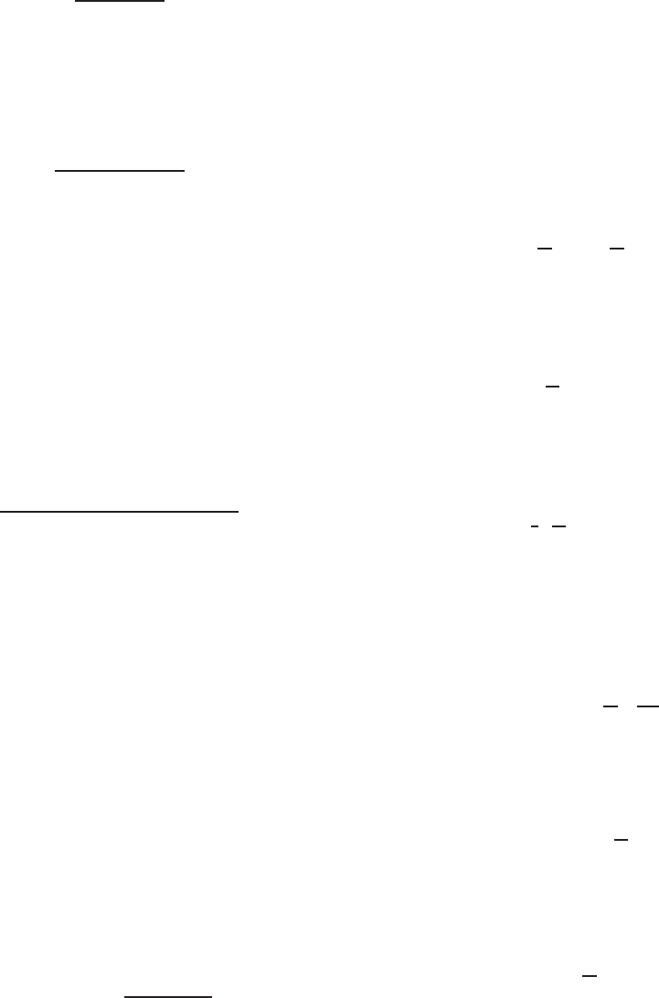
It should be noted that Eq. (4.40) applies to elastic
buckling of cold-formed steel beams when the computed
theoretical buckling stress is less than or equal to the
proportional limit σ
pr
. However, when the computed stress
exceeds the proportional limit, the beam behavior will be
governed by inelastic buckling. For extremely short beams,
the maximum moment capacity may reach the full plastic
moment M
p
for compact sections. A previous study
4.16
has
indicated that for wide-flange beams having an average
shape factor of 10/9,
M
p
=
10
9
M
y
=
10
9
F
y
S
x
(4.42)
where M
p
= full plastic moment
M
y
= yield moment, = S
x
F
y
This means that the stress in extreme fibers may reach
a hypothetical value of
10
9
F
y
when L
2
S
xc
/dI
yc
∼
=
0ifthe
elastic section modulus is used to compute the moment.
As in the previous design approach for compression
members (Ref. 1.4), the effective proportional limit (or the
upper limit of the elastic buckling) may be assumed to be
equal to one-half the maximum stress, that is,
σ
pr
=
1
2
10
9
F
y
= 0.56F
y
(4.43)
As shown in Fig. 4.26, assuming K
y
= 1andL
y
=
L, the corresponding L
2
S
xc
/dI
yc
ratio for σ
cr
= σ
pr
is
1.8π
2
EC
b
/F
y
.
When the theoretical critical stress exceeds σ
pr
, the crit-
ical stress for inelastic buckling may be represented by the
following parabolic equation:
(σ
cr
)
I
= F
y
A −
1
B
F
y
σ
cr
(4.44)
where A and B are constants that can be determined by the
following conditions:
1. When L = 0,
(σ
cr
)
I
=
10
9
F
y
(4.45)
2. When L
2
S
xc
/(dI
yc
) = 1.8π
2
EC
b
/F
y
,
(σ
cr
)
I
= 0.56F
y
(4.46)
By solving Eq. (4.44), A and B are found as follows:
A =
10
9
(4.47)
B = 3.24 (4.48)
126 4 FLEXURAL MEMBERS
Figure 4.26 Maximum lateral–torsional buckling stress for I-
beams (K
y
= 1andL
y
=L).
Therefore Eq. (4.44) can be rewritten as
(
σ
cr
)
I
= F
y
10
9
−
1
3.24
F
y
(
σ
cr
)
e
=
10
9
F
y
1 −
10
36
F
y
(
σ
cr
)
e
(4.49)
where
(
σ
cr
)
e
is the elastic buckling stress for
lateral–torsional buckling a nd
(
σ
cr
)
I
is the theoretical
equation for lateral–torsional buckling in the inelastic
range.
Even though the maximum stress computed by Eq. (4.49)
as shown in Fig. 4.26 is larger than F
y
, a conservative
approach has been used by AISI to limit the maximum
stress to F
y
.
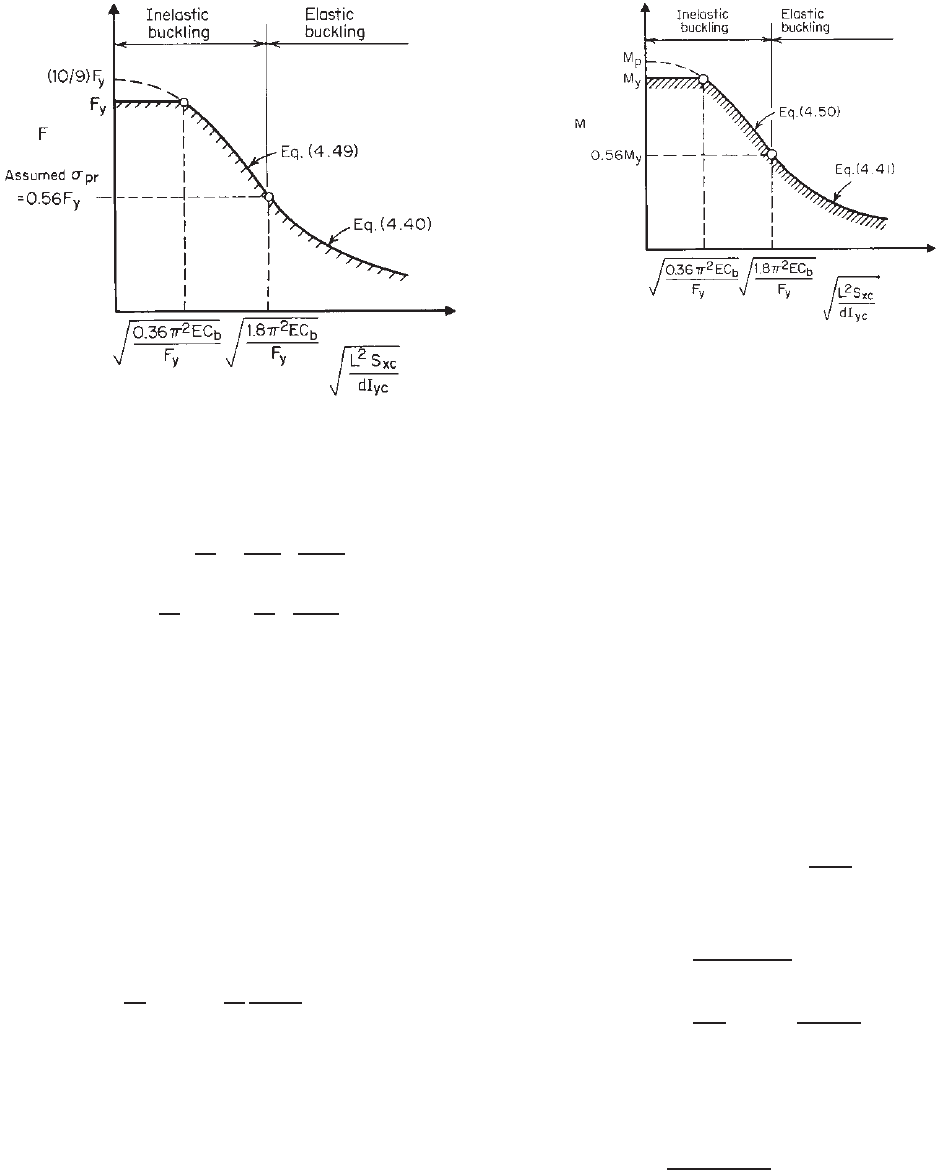
By using the inelastic critical buckling stress given in Eq.
(4.49) and the section modulus relative to the compression
fiber, the inelastic critical moment for lateral–torsional
buckling of I-beams can be computed as follows:
(M
cr
)
I
= (σ
cr
)
I
S
xc
≤ M
y
=
10
9
M
y
1 −
10
36
M
y
(M
cr
)
e
≤ M
y
(4.50)
where M
y
is the yield moment and (M
cr
)
e
is the elastic
critical moment defined in Eq. (4.41). Equation (4.50) was
used in Section C3.1.2 of the 1996 edition of the AISI
Specification. It was used only for (M
cr
)
e
> 0.56M
y
as
shown in Fig. 4.27. Hill has demonstrated that the equations
derived for I-sections can also be used for channels with
satisfactory accuracy.
4.17
For cold-formed steel design, Eqs. (4.40) and (4.49) were
used in the 1968 and 1980 editions of the AISI Specification
Figure 4.27 Maximum lateral–torsional buckling moment for
I-beams (K
y
= 1andL
y
= L).
to develop the design equations for lateral–torsional buck-
ling of I-beams and channels. In the 1986 and 1996 editions
of the AISI Specification, in addition to the use of Eqs.
(4.41) and (4.50) for determining the critical moment, new
design formulas for lateral–torsional buckling strength were
added as alternative methods. These additional equations
were developed from the previous study conducted by
Pekoz and Winter on flexural–torsional buckling of thin-
walled sections under eccentric load. The AISI Specifi-
cation also considers the effect of local buckling on the
lateral–torsional buckling strength of beams.
Specifically, Section C3.1.2 of the 1996 edition of the
AISI Specification provided Eq. (4.51) for computing the
elastic critical moment on the basis of the flexural–torsional
buckling theory. It is used for singly and doubly symmetric
sections bending about the symmetry axis perpendicular to
the web:
(M
cr
)
e
= C
b
r
0
A
√
σ
ey
σ
t
(4.51)
where A is the full cross-sectional area and
σ
ey
=
π
2
E
(K
y
L
y
/r
y
)
2
(4.52)
σ
t
=
1
Ar
2
0
GJ +
π
2
EC
w
(K
t
L
t
)
2
(4.53)
where K
y
,K
t
= effective length factors for bending about
the y axis and for twisting
L
y
,L
t
= unbraced length for bending about the y
axis and for twisting
r
0
=
r
2
x
+ r
2
y
+ x
2
0
r
x
,r
y
= radii of gyration of the cross section
about the centroidal principal axes
BENDING STRENGTH AND DEFLECTION 127
x
0
= distance from the shear center to the
centroid along the principal x axis, taken
as negative
Other terms were defined previously. For singly symmetric
sections, the x axis is the axis of symmetry oriented such
that the shear center has a negative x coordinate. The
basis for Eq. (4.51) is discussed by Pekoz in Ref. 3.17.
A comparison of Eqs. (4.41) and (4.51) shows that these
two equations give similar results for channels having
I
x
>I
y
.
3.17
However, for channel sections having I
x
<
I
y
with large K
y
L
y
/r
y
ratios, the simplified Eq. (4.41)
provides very conservative results as compared with Eq.
(4.51).
For singly symmetric sections bending about the
centroidal axis perpendicular to the symmetry axis, the
elastic critical moment based on the flexural–torsional
buckling theory can be computed by using Eq. (4.54):
(M
cr
)
e
=
C
s
Aσ
ex
[j + C
s
j
2
+ r
2
0
(σ
t
/σ
ex
)]
C
TF
(4.54)
where C
s
=+1 for moment causing compression on
shear center side of centroid
C
s
= –1 for moment causing tension on shear
center side of centroid
σ
ex
= π
2
E/(K
x
L
x
/r
x
)
2
(4.55)
C
TF
= 0.6 − 0.4(M
1
/M
2
),whereM
1
is the smaller
and M
2
the larger bending moment at the
ends of the unbraced length and M
1
/M
2
,the
ratio of end moments, is positive when M
1
and M
2
have the same sign (reverse
curvature bending) and negative when they
are of opposite sign (single curvature
bending). When the bending moment at any
point within an unbraced length is larger
than that at both ends of this length and for
members subject to combined axial load and
bending moment, C
TF
shall be taken as
unity.
K
x
= effective length factor for bending about the
x axis
L
x
= unbraced length for bending about the x axis
and
j =
1
2l
y
A
x
3
dA +
A
xy
2
dA
− x
0
(4.56)
= β
y
/2 (see Appendix C for computation of β
y
)
(4.57)
Other terms were defined previously.
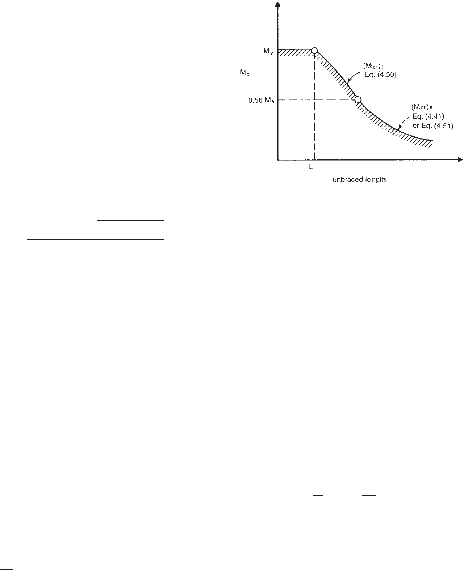
Figure 4.28 Elastic and inelastic critical lateral buckling
moments for members bending about centroidal axis perpendicular
to the web.
The derivation of Eq. (4.54) is presented in Chapter 6
for beam–columns. See Eqs. (6.46) and (6.50).
It should be noted that Eqs. (4.51) and (4.54) can be used
only when the computed value of (M
cr
)
e
does not exceed
0.56M
y
, which is considered to be the upper limit for the
elastic buckling range. When the computed (M
cr
)
e
exceeds
0.56M
y
, the inelastic critical moment can be computed from
Eq. (4.50). The elastic and inelastic critical moments are
shown in Fig. 4.28.
The above discussion dealt only with the lateral–torsional
buckling strength of locally stable beams. For locally
unstable beams, the interaction of the local buckling of
compression elements and the overall lateral–torsional
buckling of beams may result in a reduction of the
lateral–torsional buckling strength of the member. The
effect of local buckling on the critical moment was consid-
ered in Section C3.1.2 of the 1986 and 1996 editions of the
AISI specification, in which the nominal lateral–torsional
buckling strength w as determined as follows:
M
n
= M
c
S
c
S
f
= S
c
M
c
S
f
= S
c
F
c
(4.58)
where M
c
= elastic or inelastic critical moment whichever
is applicable
S
c
= elastic section modulus of effective section
calculated a t stress F
c
(= M
c
/S
f
) in extreme
compression fiber
S
f
= elastic section modulus of full unreduced
section for extreme compression fiber
F
c
= elastic or inelastic critical lateral–torsional
buckling stress
128 4 FLEXURAL MEMBERS
Table 4.2 Coefficients K in Eq. (4.59)
3.3
Loads Act At
Centroid Top Flange Bottom Flange
GJ
EC
w
L
2
0.4 86.4 51.3 145.6
4 31.9 20.2 50.0
8 25.6 17.0 38.2
16 21.8 15.4 30.4
24 20.3 15.0 27.2
32 19.6 14.8 26.3
48 19.0 14.8 23.5
64 18.3 14.9 22.4
80 18.1 14.9 21.7
96 17.9 15.1 21.1
160 17.5 15.3 20.0
240 17.4 15.6 19.3
320 17.2 15.7 18.9
400 17.2 15.8 18.7
In Eq. (4.58), the ratio of S
c
/S
f
was used to account for the
effect of local buckling on the lateral–torsional buckling
strength of beams. The same design concept is used in the
North American Specification.
The equations developed above for the uniform bending
moment can also be used for other loading conditions with
reasonable accuracy.
1.161,4.18
If more accurate results are
desired, the theoretical critical value for a concentrated load
at the center of a simply supported beam can be computed
as
3.3
P
cr
= K
EI
y
GJ
L
2
(4.59)
where K is a coefficient to be taken from Table 4.2 based
on the parameter GJL
2
/EC
w
. For symmetrical I-sections,
C
w
I
y
d
2
/4, where d is the depth of the section.
For a uniformly distributed load, the critical load is
w
cr
= K
EI
y
GJ
L
3
(4.60)
where K is to be taken from Table 4.3.
4.2.3.2 Point-Symmetric Sections Point-symmetric sec-
tions such as Z-sections with equal flanges will buckle later-
ally at lower strengths than doubly and singly symmetric
sections. A conservative design approach has been used in
the AISI Specification and is being used in the North Amer-
ican Specification, in which the elastic critical moment is
taken to be one-half of those permitted for I-beams or chan-
nels. Therefore instead of using Eq. (4.51), the following
equation is used for determining the elastic critical moment
for point-symmetric Z-sections bending about the centroidal
Table 4.3 Coefficients K in Eq. (4.60)
3.3
Loads Act At
Centroid Top Flange Bottom Flange
GJ
EC
w
L
2
0.4 143.0 92.9 222.0
4 53.0 36.3 77.3
8 42.6 30.4 59.4
16 36.3 27.4 48.0
24 33.8 26.6 43.4
32 32.6 26.1 40.4
48 31.5 25.8 37.6
64 30.5 25.7 36.2
80 30.1 25.7 35.1
128 29.0 26.0 33.3
200 29.0 26.4 32.1
280 28.8 26.5 31.4
360 28.7 26.6 31.0
400 28.6 26.6 30.7
axis perpendicular to the web:
(M
cr
)
e
=
1
2
(C
b
r
0
A
√
σ
ey
σ
t
) (4.61)
In lieu of Eq. (4.61), the following simplified equation
can be used to calculate the elastic critical moment for Z-
sections:
(
M
cr
)
e
=
C
b
π
2
EdI
yc
2
K
y
L
y
2
(4.62)
All symbols used in Eqs. (4.61) and (4.62) are defined in
Section 4.2.3.1.
4.2.3.3 North American Design Criteria for Lateral–
Torsional Buckling Strength of Singly, Doubly, and Point-
Symmetric Sections The following excerpts are adapted
from Section C3.1.2.1 of the 2007 edition of the North
American Specification, which provides the needed design
equations for computing the critical lateral–torsional buck-
ling stress.
1.345
The application of the North American
design criteria is illustrated in Examples 4.9–4.11.
C3.1.2.1 Lateral–Torsional Buckling Strength
[Resistance] of Open Cross-Section Members
The provisions of Section C3.1.2.1 of the specification shall
apply to I-, Z-, C-, and other singly symmetric section flexural
members (not including multiple-web deck, U- and closed
box-type members, and curved or arch members) subject
to lateral–torsional buckling. The provisions of this section
shall not apply to laterally unbraced compression flanges of
otherwise laterally stable sections. See Section 4.2.5 for C- and
Z-purlins in which the tension flange is attached to sheathing.
BENDING STRENGTH AND DEFLECTION 129
For laterally unbraced segments of singly, doubly,and
point-symmetric sections subject to lateral–torsional buckling,
the nominal flexural strength [moment resistance], M
n
,shall
be calculated in accordance with the equation
M
n
= S
c
F
c
(4.63)
b
= 1.67 (ASD)
φ
b
=
0.90 (LRFD)
0.90 (LSD)
where S
c
is the elastic section modulus of the effective section
calculated relative to extreme compression fiber at F
c
and F
c
shall be determined as follows: For F
e
≥ 2.78F
y
,the member
segment is not subject to lateral-torsional buckling at bending
moments less than or equal to M
y
. The available flexural
strength [moment resistance] shall be determined in accordance
with Section 4.2.2.1.
For 2.78F
y
>F
e
> 0.56F
y
,
F
c
=
10
9
F
y
1 −
10F
y
36F
e
(4.64a)
For F
e
≤ 0.56F
y
,
F
c
= F
e
(4.64b)
where F
y
is the design yield stress as determined in accordance
with Section 2.2 and F
e
is the elastic critical lateral–torsional
buckling stress calculated in accordance with (a) or (b):
(a) For singly, doubly, and point-symmetric sections:
i. For bending about the symmetry axis:
F
e
=
⎧
⎪
⎪
⎪
⎪
⎨
⎪
⎪
⎪
⎪
⎩
C
b
r
o
A
S
f
√
σ
ey
σ
t
for singly and doubly
symmetric sections (4.65a)
C
b
r
o
A
2S
f
√
σ
ey
σ
t
for point - symmetric
sections (4.65b)
C
b
=
12.5M
max
2.5M
max
+3M
A
+4M
B
+3M
C
(4.66)
where M
max
= absolute value of maximum moment in
unbraced segment
M
A
= absolute value of moment at quarter
point of unbraced segment
M
B
= absolute value of moment at centerline
of unbraced segment
M
C
= absolute value of moment at
three-quarter point of unbraced segment
and C
b
shall be permitted to be conservatively taken as
unity for all cases. For cantilevers or overhangs where
the free end is unbraced, C
b
shall be taken as unity. The
polar radius of gyration of the cross section about the
shear center is given as
r
o
=
r
2
x
+ r
2
y
+ x
2
o
where r
x
,r
y
= radii of gyration of cross section about
centroidal principal axes
x
o
= distance from shear center to centroid
along principal x axis, taken as negative
Here A is the full unreduced cross-sectional area, S
f
is
the elastic section modulus of the full unreduced section
relative to the extreme compression fiber, and
σ
ey
=
π
2
E
(K
y
L
y
/r
y
)
2
(4.67)
where E = modulus of elasticity of steel
K
y
= effective length factors for bending about y
axis
L
y
= unbraced length of member for bending
about y axis
and
σ
t
=
1
Ar
2
o
GJ +
π
2
EC
w
(
K
t
L
t
)
2
(4.68)
where G = shear modulus
J = St. Venant torsion constant of cross section
C
w
= torsional warping constant of cross section
K
t
= effective length factors for twisting
L
t
= unbraced length of member for twisting
For singly symmetric sections, t he x axis shall be the
axis of symmetry oriented such that the shear center has
a negative x coordinate.
For point-symmetric sections, such as Z-sections, the
x axis shall be the centroidal axis perpendicular to the
web.
Alternatively, F
e
shall be permitted to be calcu-
lated using the equation given in (b) for doubly
symmetric I-sections, singly symmetric C-sections, or
point-symmetric Z-sections.
ii. For singly symmetric sections bending about the
centroidal axis perpendicular to the axis of symmetry,
F
e
=
C
s
Aσ
ex
C
TF
S
f
j + C
s
j
2
+ r
2
o
(
σ
t
/σ
ex
)
(4.69)
where C
s
equals +1 for the moment causing compres-
sion on the shear center side of the centroid and -1 for
the moment causing tension on the shear center side of
the centroid and
σ
ex
=
π
2
E
(
K
x
L
x
/r
x
)
2
(4.70)
where K
x
= effective length f actors for bending about x
axis
L
x
= unbraced length of member for bending
about x axis
130 4 FLEXURAL MEMBERS
and
C
TF
= 0.6 − 0.4
M
1
M
2
(4.71)
where M
1
and M
2
are the smaller and larger bending
moments, respectively, at the ends of the unbraced
length in the plane of bending; M
1
/M
2
, the ratio of end
moments, is positive when M
1
and M
2
have the same
sign (reverse-curvature bending) and negative when they
are of opposite sign (single-curvature bending). When the
bending moment at any point within an unbraced length
is larger than that at both ends of this length, C
TF
shall
be taken as unity,
j =
1
2I
y
A
x
3
dA +
A
xy
2
dA
− x
o
(4.72)
(b) For I-sections, singly symmetric C-sections, or Z-sections
bent about the centroidal axis perpendicular to the web (x
axis), the following equations shall be permitted to be used
in lieu of (a) to calculate Fe:
F
e
=
⎧
⎪
⎪
⎪
⎪
⎪
⎪
⎪
⎪
⎪
⎨
⎪
⎪
⎪
⎪
⎪
⎪
⎪
⎪
⎪
⎩
for doubly symmetric
I - sections and
C
b
π
2
EdI
yc
S
f
(K
y
L
y
)
2
singly symmetric
C - sections (4.73a)
C
b
π
2
EdI
yc
2S
f
(K
y
L
y
)
2
for point - symmetric
Z - sections (4.73b)
where d = depth of section
I
yc
= moment of inertia of compression portion of
section about centroidal axis of entire section
parallel to web using full unreduced section
See (a) for definition of other variables.
According to Section C3.1.2.1 of the 2007 North Amer-
ican Specification, it can be seen that for members bent
about the centroidal axis perpendicular to the web calcu-
lation of lateral–torsional buckling strength is unnecessary
when the unbraced length does not exceed a length, L
u
,
which is determined for M
e
= 2.78M
y
(or F
e
= 2.78F
y
)
(see Fig. 4.28). The following equations are given in
Section 1.4 of Part II of the AISI Design Manual
1..349
for
computing L
u
:
(a) For singly, doubly, and point-symmetric sections,
L
u
=
⎧
⎨
⎩
GJ
2C
1
+
C
2
C
1
+
GJ
2C
1
2
0.5
⎫
⎬
⎭
0.5
(4.74)
where
1. For singly and doubly symmetric sections,
C
1
=
7.72
AE
K
y
F
y
S
f
C
b
πr
y
2
C
2
=
π
2
EC
w
(K
t
)
2
Figure 4.29 Example 4.9.
2. For point-symmetric sections,
C
1
=
30.9
AE
K
y
F
y
S
f
C
b
πr
y
2
C
2
=
π
2
EC
w
(K
t
)
2
(b) For I-, C-, or Z-sections bent about the centroidal axis
perpendicular to the web (x axis), in lieu of (a), the
following equations may be used:
1. For doubly symmetric I-sections and singly
symmetric C-sections,
L
u
=
0.36C
b
π
2
EdI
yc
F
y
S
f
K
y
2
0.5
(4.75a)
2. For point-symmetric Z-sections,
L
u
=
0.18C
b
π
2
EdI
yc
F
y
S
f
K
y
2
0.5
(4.75b)
In addition, Part II of the Design Manual provides
beam design charts for determining the nominal flexural
strengths of C-sections and Z-sections with lips. These
charts were prepared for F
y
= 33, 50 and 55 ksi (228, 345,
and 379 MPa; 2.32, 3.52, and 3.87 × 10
3
kg/cm
2
) with
C
b
= 1.0. The torsional unbraced length (K
t
L
t
) is assumed
to be equal to the unbraced length about the y axis (K
y
L
y
).
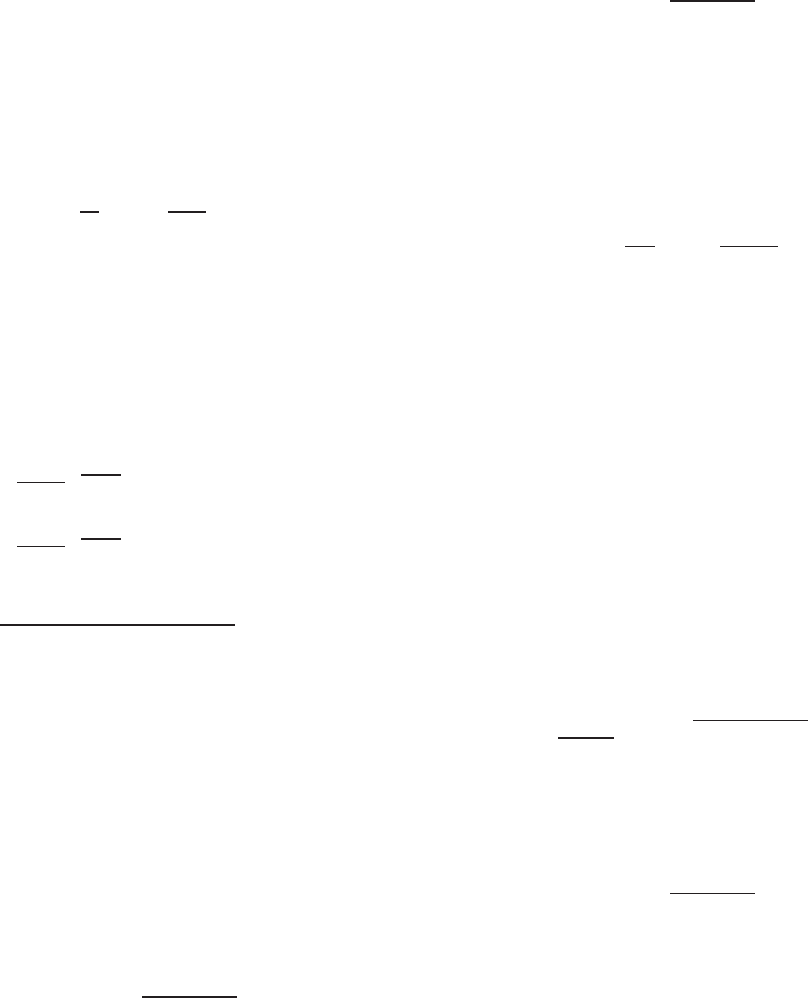
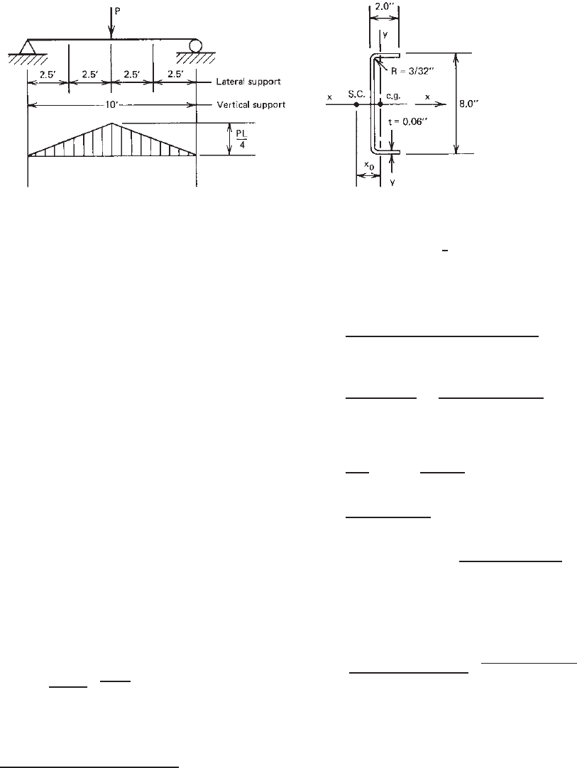
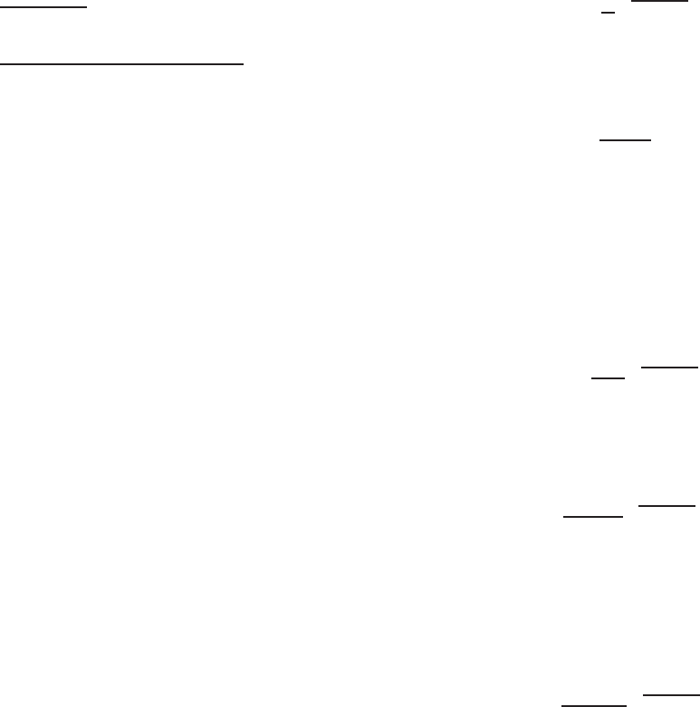
Example 4.9 For the I-beam used in Example 4.1, what is
the maximum spacing of lateral supports in order to use the
nominal moment of 312.35 in.-kips determined for section
strength? Assume that the I-section is to be used as a simply
supported beam with a span length of 10 ft to support a
uniform load (see Fig. 4.29).
SOLUTION. In order to use the nominal moment for
section strength, the maximum spacing of lateral s upports
can be determined from the following equation:
M
n
for section strength = M
n
for lateral–torsional
buckling strength
From Eqs. (4.4) and (4.63),
S
e
F
y
= S
c
F
c
BENDING STRENGTH AND DEFLECTION 131
As shown in Fig. 4.28, when K
y
L
y
≤ L
u
, M
c
= M
y
(or
F
c
= F
y
)andS
e
= S
c
. Assume that the elastic critical
lateral–torsional buckling stress of the I-section is deter-
mined according to Section C3.1.2.1(b) of the North Amer-
ican specification. For F
c
= F
y
,
F
e
≥ 2.78F
y
Substituting Eq. (4.73a) for F
e
into the above expression
yields
π
2
EC
b
dI
yc
S
f
(K
y
L
y
)
2
≥ 2.78F
y
Therefore,
K
y
L
y
≤
π
2
EC
b
dI
yc
/(2.78S
f
F
y
)
where E = 29.5 × 10
3
ksi
C
b
= 1.0 (assumed value)
d = 8.0 in.
F
y
= 50 ksi
K
y
= 1.0
I
yc
= 0.724 in.
4
(see the following calculation)
Area A Distance from Ax
2
Element (in.
2
) y Axis, x (in.) (in.
4
)
Flanges 4(1.6775)(0.135) = 0.9059 1.1613 1.2217
Corners 4(0.05407) = 0.2163 0.1564 0.0053
Webs 2(7.355)(0.135) =
1.9859 0.0675 0.0090
Total 3.1081 1.2360
I
flanges
= 4 ×
1
12
×0.135(1.6775)
3
=0.2124
I
y
= 1.4484 in.
4
I
yc
=
1
2
I
y
= 0.724 in.
4
S
f
= 6.54 in.
3
(see the following calculation)
Area A Distance from Ay
2
Element (in.
2
) Mid depth y(in.) (in.
4
)
Flanges 4(1.6775)(0.135) = 0.9059 3.9325 14.0093
Corners 4(0.05407) = 0.2163 3.8436 3.1955
Webs 2(7.355)(0.135) =
1.9859 0 0
Total 3.1081 17.2048
2I
web
= 2 ×
1
12
× (0.135)(7.355)
3
8.9522
I
x
= 26.1570 in.
4
S
f
=
I
x
8/2
= 6.54 in.
3
The maximum unbraced length between lateral
supports is
L
y
=
π
2
(29,500)(1)(8)(0.724)
2.78(6.54)(50)
= 43.1in.
Alternatively, the above unbraced length can be calculated
directly from Eq. (4.75a). Actually, the beam may be braced
laterally at one-third span length with an unbraced length of
Figure 4.30 Lateral supports.
Figure 4.31 Example 4 .10.
40 in., as shown in Fig. 4.30. For segment CD, C
b
= 1.01,
which is practically the same as the assumed value of 1.0.
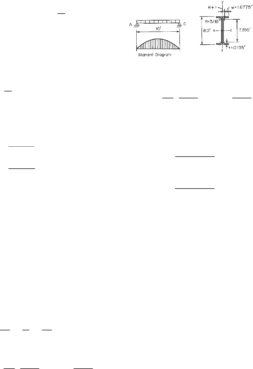
Example 4.10 Determine the allowable uniform load if
the I-beam used in Example 4.9 is braced laterally at both
ends and midspan. See Fig. 4.31. Use the value of C
b
determined by the formula included in the North American
Specification and F
y
= 50 ksi. Use the ASD method and the
LRFD method with an assumed dead load–live load ratio
D/L =
1
5
.
SOLUTION
A. ASD Method
1. Nominal Moment for Section Strength. From Example
4.1, the nominal moment for section strength
according to Eq. (4.4) is
(M
n
)
1
= S
e
F
y
= 312.35 in.-kips
2. Nominal Moment for Lateral–Torsional Buckling
Strength. From Example 4.9, S
f
= 6.54 in.
3
and
I
yc
= 0.724 in.
4
Considering the lateral supports at
both ends and midspan and the moment diagram
shown in Fig 4.31, the bending coefficient C
b
for
132 4 FLEXURAL MEMBERS
segment AB can be calculated by using Eq. (4.66) as
follows:
C
b
=
12.5M
max
2.5M
max
+ 3M
1
+ 4M
2
+ 3M
3
where M
max
= wL
2
/8 at midspan
M
1
= 7wL
2
/128 at
1
/
4
point of unbraced
segment
M
2
= 12wL
2
/128 at midpoint of unbraced
segment
M
3
= 15wL
2
/128 at
3
/
4
point of unbraced
segment
C
b
=
12.5(wL
2
/8)
2.5(wL
2
/8) + 3(7wL
2
/128)
+4(12wL
2
/128) + 3(15wL
2
/128)
= 1.30
Using Eq. (4.73a), with K
y
= 1.0,
F
e
=
π
2
EC
b
dI
yc
S
f
(K
y
L
y
)
2
=
π
2
(29,500)(1.30)(8)(0.724)
(6.54)
(
5 × 12
)
2
= 93.11 ksi
0.56F
y
= 28.00 ksi
2.78F
y
= 139.00 ksi
Since 2.78F
y
>F
e
> 0.56F
y
, from Eq. (4.64a)
F
c
=
10
9
F
y
1 −
10F
y
36F
e
=
10
9
(
50
)
1 −
10
(
50.0
)
36
(
93.11
)
= 47.27 ksi
Based on Eq. (4.63), the nominal moment for lateral–
torsional buckling strength is
(M
n
)
2
= S
c
F
c
in which S
c
is the elastic section modulus of the
effective section calculated at a compressive stress of
f = 47.27 ksi. By using the procedure illustrated in
Example 4.1, S
c
= 6.294 in.
3
Therefore, the nominal
moment for lateral–torsional buckling strength is
(M
n
)
2
= (6.294)(47.27) = 297.5in.-kips
3. Allowable Uniform Load. Because (M
n
)
2
<(M
n
)
1
,
lateral–torsional buckling strength governs the design.
Use M
n
= 297.5 in.-kips to determine the allowable
moment as follows:
M
a
=
M
n
b
=
297.5
1.67
= 178.14 in.-kips
The maximum moment at midspan is wL
2
/8 ft-kips:
1
8
wL
2
(
12
)
= 178.14 in.-kips
Then the allowable uniform load is
w = 1.188 kips/ft
It should be noted that the allowable load computed
above is based on the bending moment. It should also
be checked for shear, web crippling, deflection, and
other requirements as applicable.
B. LRFD Method.
Using the same method employed above for the ASD
method, the governing nominal moment for lateral–
torsional buckling strength is
M
n
= 297.5in.-kips
Since the I-section has an unstiffened flange, the resistance
factor as listed in Table 3.1 and discussed in Section 4.2.1
is 0.90.
Therefore, the design moment is
φ
b
M
n
= 0.90(297.5) = 267.75 in.-kips
Based on the load combination of Eq. (3.5a), the required
moment is
M
u
= 1.4M
D
where M
D
is the bending moment due to dead load.
Similarly, based on the load combination of Eq. (3.5b),
the required moment is
M
u
= 1.2M
D
+ 1.6M
L
= 1.2M
D
+ 1.6(5M
D
) = 9.2M
D
where M
L
is the bending moment due to live load. A
comparison of the above computations indicates that for a
given member the load combination of Eq. (3.5b) allows
a smaller moment M
D
than the load combination of
Eq. (3.5a). Therefore, the bending moment M
D
can be
computed from M
u
= φ
b
M
n
as follows:
9.2M
D
= 267.75 in.-kips
Therefore,
M
D
=
267.75
9.2
= 29.10 in.-kips
M
L
= 5M
D
= 145.50 in-kips
Theallowablemomentis
M
a
= M
D
+ M
L
= 29.10 + 145.50 = 174.60 in.-kips
The allowable uniform load can be calculated as follows:
1
8
wL
2
(
12
)
= 174.60 in-kips w = 1.164 kips/ft
It can be seen that the allowable uniform load computed
on the basis of the LRFD method is similar to that computed
from the ASD method. The difference is only about 2%.
BENDING STRENGTH AND DEFLECTION 133
Figure 4.32 Example 4 .11.
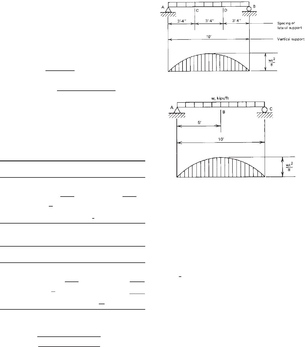
Example 4.11 For the singly symmetric channel section
(8 × 2 × 0.06 in.) shown in Fig. 4.32, determine the
nominal moment for lateral–torsional buckling strength
according to Section C 3.1.2.1 of the 2007 edition of the
North American Specification. Assume that the channel is
used as a simply supported beam to support a concentrated
load at midspan and lateral supports are located at one-
fourth of the span length. Use F
y
= 33 ksi, K
y
L
y
= K
t
L
t
=
2.5ft.
SOLUTION
1. Sectional Properties. By using the design formulas
given in Part I of the AISI design manual, the
following full-section properties can be calculated:
A = 0.706 in.
2
x
0
=−0.929 in.
S
f
= 1.532 in.
3
r
o
= 3.14 in.
r
x
= 2.945 in. J = 0.000848 in.
4
r
y
= 0.569 in. C
w
= 2.66 in.
6
2. Elastic Critical Lateral–Torsional Buckling Stress, F
e
.
Because the given singly symmetric channel section is
subject to a moment bending about the symmetry axis
(x axis), the elastic critical lateral–torsional buckling
stress can be determined according to Eq. (4.65a) as
follows:
F
e
=
C
b
r
0
A
S
f
√
σ
ey
σ
t
For two central segments, the value of C
b
can be
computed from Eq. (4.66) as follows:
C
b
=
12.5M
max
2.5M
max
+ 3M
1
+ 4M
2
+ 3M
3
where M
max
= PL/4 at midspan
M
1
= 5PL/32 at
1
/
4
point of unbraced
segment
M
2
= 6PL/32 at midpoint of unbraced
segment
M
3
= 7PL/32 at
3
4
point of unbraced
segment
Then
C
b
=
12.5(P L/4)
2.5(P L/4) + 3(5PL/32)
+4(6PL/32) + 3(7PL/32)
= 1.25
σ
ey
=
π
2
E
K
y
L
y
/r
y
2
=
π
2
(
29,500
)
(
2.5 × 12/0.569
)
2
= 104.74 ksi
σ
t
=
1
Ar
2
0
GJ +
π
2
EC
w
(
K
t
L
t
)
2
=
1
(0.706)(3.14)
2
(11,300)(0.000848)
+
π
2
(29,500)(2.66)
(2.5 × 12)
2
= 125.0ksi
Therefore, the e lastic critical lateral–torsional buck-
ling stress is
F
e
=
(
1.25
)(
3.14
)(
0.706
)
(
1.532
)
(
104.74
)(
125.0
)
= 206.96 ksi
3. Critical Lateral–Torsional Buckling Stress, F
c
0.56F
y
= 18.48 ksi 2.78F
y
= 91.74 ksi
Since F
e
> 2.78 F
y
, the member segment is not
subject to lateral–torsional buckling. The nominal
moment should be determined in accordance with
Section 4.2.2.1 in this volume or C3.1.1(a) of the
Specification:
F
c
= F
y
134 4 FLEXURAL MEMBERS
4. Nominal Moment M
n
.AccordingtoSection4.2.2.1
the nominal moment based on section strength can be
calculated a s follows:
M
n
= S
e
F
y
By using the same procedure illustrated in Example
4.1 w ith f = F
y
, the elastic section modulus of the
effective section is
S
e
= 1.211 in.
3
Therefore, the nominal moment is
M
n
= (1.211)(33) = 39.96 in.-kips
5. It should be noted that the above calculation is based
on Section C3.1.2.1(a) of the AISI North American
Specification.
1.345
If Section C3.1.2.1(b) is used to
compute F
e
, then, according to Eq. (4.73a),
F
e
=
π
2
EC
b
dI
yc
S
f
(K
y
L
y
)
2
=
π
2
(
29,500
)(
1.25
)(
8.0
)(
0.1145
)
(
1.532
)(
2.5 × 12
)
2
= 241.78 ksi
Since F
e
> 2.78F
y
= 91.74 ksi, similar to Item 4
above, the compressive stress is
f = F
y
= 33 ksi
The elastic section modulus of the effective section is
S
c
= 1.211 in.
3
The nominal moment is
M
n
= 39.96 in.-kips
It can be seen that for the given channel section
with quarter-point lateral supports, Sections C3.1.2.1(a)
and C3.1.2.1(b) of the North American Specification give
the same nominal moment for lateral–torsional buckling
strength.
4.2.3.4 Closed-Box Sections Closed sections such as
box shapes have relatively larger torsional stiffness as
compared with open sections such as I-beams, C-sections,
and Z-sections discussed in Sections 4.2.3.1 and 4.2.3.2. As
far as lateral–torsional buckling is concerned, these closed,
double-web sections are more stable than single-web open
sections, and therefore any use of closed-box sections will
result in an economical design if lateral–torsional stability
of the beam is essential.
In Ref. 4.18, Winter indicated that for closed-box beams
the bending strength is unaffected by lateral–torsional buck-
ling even when the length-to-width ratio is as high as 100
for a steel having a yield stress of 33 ksi (228 MPa or 2320
kg/cm
2
).
Previous editions of the AISI Specification contained
in Section D3.3a conservative design provision for
lateral–torsional buckling of closed-box beams, in which
laterally unbraced box sections can be designed without
any strength reduction for lateral–torsional buckling
consideration if the ratio of the unsupported length to the
distance between the webs of the section does not exceed
0.086E/F
y
. In 1999, this design requirement was replaced
by Section C3.1.2.2 in the Supplement to the 1996 edition
of the AISI Specification.
1.333
The same design provisions
are retained in the North American Specification, except
that the laterally unbraced length, L, was clarified to be
K
y
L
y
.
For a closed-box section subjected to a uniform bending
moment as shown in Fig. 4.23, the elastic critical moment
for lateral–torsional buckling is
3.84
(
M
cr
)
e
=
π
L
EI
y
GJ
All terms are defined in Section 4.2.3.1, except that the
torsional constant J maybedeterminedbythefollowing
equation for a closed-box section having a uniform
thickness
4.157
:
J =
2b
2
d
2
t
b + d
where b = midline or centerline dimension of flange
d = midline or centerline dimension of web
t = wall thickness
When a closed-box section is subject to a nonuniform
bending moment, the above equation for the elastic critical
moment can be modified by a bending coefficient C
b
as
follows:
(
M
cr
)
e
=
C
b
π
L
EI
y
GJ (4.76)
Consequently, the elastic critical lateral–torsional buck-
ling stress F
e
can be determined by Eq. (4.77) as given in
Section C3.1.2.2 of the 2007 edition of the North American
Specification as follows
1.345
:
F
e
=
C
b
π
K
y
L
y
S
f
EI
y
GJ (4.77)
in which S
f
is the elastic section modulus of the full unre-
duced section relative to the extreme compression flange,
K
y
is the effective length factor, and L
y
is the unbraced
length for bending about y axis.
Based on Eq. (4.77), the following equation for L
u
can
be derived from F
e
= 2.78F
y
:
L
u
=
0.36C
b
π
F
y
S
f
EI
y
GJ (4.78)