Yu W., LaBoube R.A. Cold-Formed Steel Design
Подождите немного. Документ загружается.

BENDING STRENGTH AND DEFLECTION 135
Figure 4.33 Three possible types of supporting elastic frame for
equivalent column.
4.19
The calculation of lateral–torsional buckling strength is
unnecessary when the laterally unbraced length does not
exceed L
u
. Otherwise, the critical lateral–torsional buckling
stress F
c
should be determined from Eq. (4.64a) or Eq.
(4.64b) using the value of F
e
calculated from Eq. (4.77).
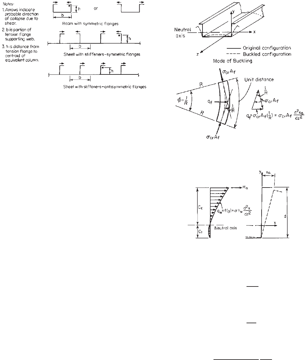
4.2.3.5 Laterally Unbraced Compression Flanges The
problems discussed in Sections 4.2.3.1 and 4.2.3.2 dealt
with the type of lateral–torsional buckling of I-beams, C-
sections, a nd Z-shaped sections for which the entire cross
section rotates and deflects in the lateral direction as a
unit. But this is not the case for U-shaped beams and the
combined sheet stiffener sections as shown in Fig. 4.33.
For the latter, when it is loaded in such a manner that
the brims and the flanges of stiffeners are in compression,
the tension flange of the beams remains straight and does
not displace laterally; only the compression flange tends to
buckle separately in the lateral direction, accompanied by
out-of-plane bending of the web, as shown in Fig. 4.34,
unless adequate bracing is provided.
The precise analysis of the lateral–torsional buckling
of U-shaped beams is rather complex. Not only to the
compression flange and the compression portion of the web
act like a column on an elastic foundation, but also the
problem is complicated by the weakening influence of the
torsional action of the flange. For this reason, the design
procedure for determining the allowable design stress for
laterally unbraced compression flanges has been based on
the considerable simplification of an analysis presented by
Douty in Ref. 4.19. See Section 2 of Part V of the 2002
edition of the AISI Cold-Formed Steel Design Manual .
1.340
When the compression flange of a U-shaped beam is
subject to the critical bending forces σ
cr
A
f
(σ
cr
being the
critical stress and A
f
the area of the flange), the c omponent
Figure 4.34 Force normal to buckled flange.
4.19
Figure 4.35 Force normal to buckled web.
4.19
of these forces normal to the buckling flange is
q
f
= σ
cr
A
f
d
2
x
a
dz
2
(4.79)
See Fig. 4.34. In the same manner, the component on a unit
strip of the buckled web as shown in Fig. 4.35 is
q
w
= σt
w
d
2
x
dz
2
(4.80)
As a result, the total lateral force R
a
transmitted to the
compression flange by the buckled web is
σ
cr
A
web
12C
c
/
(
3C
c
− C
t
)
d
2
x
a
dz
2
(4.81)
where A
web
is the area of the web and C
c
and C
t
are the
distance from the neutral axis to the extreme compression
fiber and the extreme tension fiber, respectively (Fig. 4.35).

136 4 FLEXURAL MEMBERS
Consequently, the equation of equilibrium of the
compression flange is
EI
f
d
4
x
a
dz
4
+ σ
cr
A
f
+
A
web
12C
c
/
(
3C
c
− C
t
)
d
2
x
a
dz
2
= 0
(4.82)
and the corresponding nontrivial eigenvalue leads to
σ
cr
=
π
2
E
(
L/r
)
2
(4.83)
where
r =
I
f
A
f
+ A
web
/[12C
c
/
(
3C
c
− C
t
)
]
(4.84)
which is the radius of gyration of the effective column
consisting of the compression flange and a part of the
compression portion of the web having a depth of [(3C
c
−
C
t
)/12C
c
]d,whered is the depth of the beam.
The above analysis is for the type of column supported on
an elastic foundation where the elastic support is provided
by the remaining portion of the web and the tension flange
acting together as an elastic frame. The effect of torsional
weakening in the combined flexural–torsional stability of
the effective column can be determined by the theorem of
minimum potential energy
4.19
:
U = V
1
+ V
2
+ U
w
=
1
2
L
0
[EI
y
(u
)
2
+ EC
w
(φ
)
2
+ GJ (φ
)
2
]dz
+
1
2
L
0
(C
1
u
2
− 2C
2
uφ + C
3
φ
2
)dz
−
P
2
L
0
(u
)
2
+ 2y
0
u
φ
+
I
p
A
(φ
)
2
dz (4.85)
where U = change in entire potential energy of system
consisting of effective column and its
supporting elastic frame
V
1
= strain energy accumulated in bent and twisted
column
V
2
= strain energy of deflected supporting frame
U
w
= change in potential energy of external forces
acting on system
I
y
= moment of inertia of column about its
vertical y axis
u = horizontal displacement of shear center
φ = rotation of column
J = torsional constant of column
y
0
= vertical distance between shear center and
centroid of column
I
p
= polar moment of inertia of column about its
shear center
C
w
= warping constant
C
1
= δ
φ
/
δ
u
δ
φ
− δ
2
uφ
C
2
= δ
uφ
/
δ
u
δ
φ
− δ
2
uφ
C
3
= δ
u
/
δ
u
δ
φ
− δ
2
uφ
δ
u
= horizontal displacement of shear center due
to unit load
δ
uφ
= horizontal displacement of shear center due
to unit moment
δ
φ
= rotation of column due to unit moment
By solving Eq. (4.85) and applying considerable simpli-
fications, the following expressions can be obtained for
the stability of the effective column on an elastic foun-
dation taking the torsional weakening of the flange into
consideration
4.19
:
P
cr
=
⎧
⎪
⎪
⎪
⎪
⎪
⎪
⎪
⎪
⎨
⎪
⎪
⎪
⎪
⎪
⎪
⎪
⎪
⎩
T
1 +
βL
2
π
2
P
e
P
e
whenβL
2
/P
e
≤ 30 (4.86)
T
⎛
⎝
0.6 +
2
π
βL
2
π
2
P
e
⎞
⎠
P
e
whenβL
2
/P
e
> 30 (4.87)
where P
cr
= critical load of equivalent column
P
e
= Euler critical load, π
2
EI /L
2
β = spring constant, 1/D
D = lateral deflection of column centroid due to a
unit force applied to web at level of column
centroid
L = unbraced length of equivalent column
and T , the torsional reduction factor, is determined as
follows:
T =
⎧
⎪
⎪
⎨
⎪
⎪
⎩
T
0
=
h
h + 3.4y
0
ifL ≥ L
(4.88)
T
0
L
L
=
h
h + 3.4y
0
L
L
ifL<L
(4.89)
where L
= π
4
2I(h/t)
3
= 3.7
4
I(h/t)
3
y
0
= distance from centroid of equivalent column to
its shear center
h = distance from tension flange to centroid of
equivalent column
For beams with a large distance between bracing, the
following expression for P
cr
may be used:
P
cr
= T
0
4βEI (4.90)
BENDING STRENGTH AND DEFLECTION 137
From the value of P
cr
given above, the equivalent slen-
derness ratio (L/r)
eq
can then be determined as follows:
L
r
eq
= k
π
2
E
P
cr
/A
c
=
490
√
P
cr
/A
c
(4.91)
where k is an experimental correction factor for the post-
buckling strength and equals 1/1.1 and A
c
is the cross-
sectional area of the equivalent column.
The allowable compression stress F
a
for the ASD method
can be computed from the column formula (Chapter 5) on
the basis of this equivalent slenderness ratio. To obtain
the allowable compression bending stress in the extreme
compression fiber F
b
, the axial stress F
a
may be extrap-
olated linearly from the centroid level and adjusted for
the different factors of safety used for beam yielding and
column buckling, that is,
F
b
=
c
b
C
c
y
c
F
a
(4.92)
where
c
= safety factor used for column buckling
b
= safety factor used for beam yielding
y
c
= distance from neutral axis of beam to centroid
of equivalent column
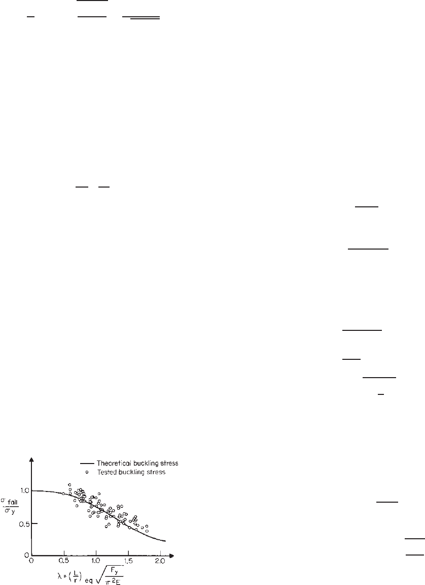
The design method developed in Ref. 4.19 has been
compared with the results of more than 100 tests (Fig. 4.36).
It has been found that discrepancies are within about
30% on the conservative side and about 20% on the
nonconservative side.
Based on the analysis and simplifications, the following
10-step design procedure has been included in the AISI
design manual since 1962.
1.159,1.349
1. Determine the location of the neutral axis a nd define
as the ‘’equivalent column” the portion of the beam from
the extreme compression fiber to a level that is a distance of
[(3C
c
− C
t
)/12C
c
]d from the extreme c ompression fiber.
Figure 4.36 Comparison between analysis and tests.
4.19
In this expression, C
c
and C
t
are the distances from the
neutral axis to the extreme compression and tension fibers,
respectively, and d is the depth of the section.
2. Determine the distance y
0
measured parallel to the
web from the centroid of the equivalent column to its shear
center. (If the cross section of the equivalent column is of
angle or T shape, its shear center is at the intersection of
the web and flange; if of channel shape, the location of
the shear center is obtained from Section 4.4. If the flanges
of the channel are of unequal width, for an approximation
take w as the mean of the two flange widths, or compute
the location of the shear center by rigorous methods. See
Appendix B.)
3. To determine the spring constant β, isolate a portion
of the member 1 in. (25.4 mm) long, apply a force of 0.001
kip (4.45 N) perpendicular to the web at the level of the
column centroid, and compute the corresponding lateral
deflection D of the centroid. Then the spring constant is
β =
0.001
D
(4.93)
4. Calculate
T
0
=
h
h + 3.4y
0
(4.94)
where h is the distance from the tension flange to the
centroid of the equivalent column in inches.
5a. If the flange is laterally braced at two or more points,
calculate
P
e
=
290,000I
L
2
(4.95)
C =
βL
2
P
e
(4.96)
L
= 3.7
4
I
h
t
3
(4.97)
where I = moment of inertia of equivalent column about
its gravity axis parallel to web, in.
4
L = unbraced length of equivalent column, in.
If C ≤ 30, compute
P
cr
= TP
e
1 +
βL
2
π
2
P
e
(4.98)
If C > 30, compute
P
cr
= TP
e
(
0.60 + 0.635
)
βL
2
P
e
(4.99)
In both cases, if L ≥ L
,
T = T
0
138 4 FLEXURAL MEMBERS
and if L<L
,
T =
T
0
L
L
(4.100)
5b. If the flange is braced at less than two points, compute
P
cr
= T
0
4βEI (4.101)
6. Determine the slenderness ratio of the equivalent
column,
KL
r
eq
=
490
√
P
cr
/A
c
(4.102)
where A
c
is the cross-sectional area of the equivalent
column.
7. From Eqs. (5.54), (5.55), and (5.56) compute the
stress F
n
corresponding to (KL/r)
eq
.
8. The design compression bending stress based on
previous factors of safety is
F
b2
= 1.15F
n
C
c
y
c
≤ F
y
(4.103)
where C
c
= distance from neutral axis of beam to extreme
compression fiber
y
c
= distance from neutral axis of beam to centroid
of equivalent column
The critical moment is M
c
= F
b2
S
f
.
Use Eq. (4.58) or (4.63) to compute M
n
.
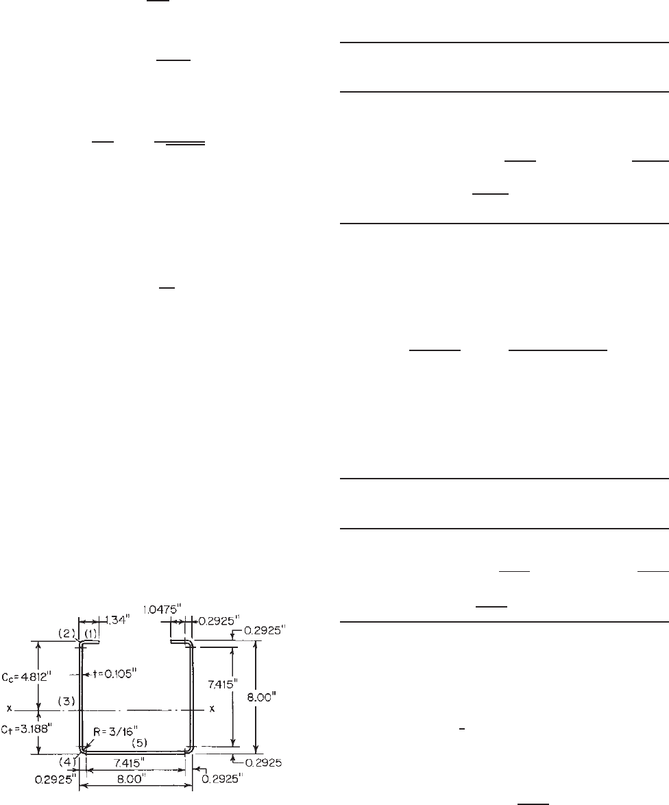
Example 4.12 Determine the design compression bending
stress in the compression flanges (top flanges of the
U-shaped section shown in Fig. 4.37. Assume that the
compression flanges are laterally braced at the third points
with unbraced lengths of 48 in. The yield point of steel is
33 ksi.
Figure 4.37 Example 4.12.
SOLUTION
1. Location of Neutral Axis and Determination of Equiv-
alent Column (Fig. 4.37)
a. Location of Neutral Axis
Distance from
Area A Top Fiber Ay
Element (in.
2
) y (in.) (in.
3
)
1 2(1.0475)(0.105) = 0.2200 0.0525 0.0116
2 2(0.0396) (Table 4.1) = 0.0792 0.1373 0.0109
3 2(7.415)(0.105) = 1.5572 4.0000 6.2288
4 2(0.0396) = 0.7920 7.8627 0.6227
5 7.415(0.105) =
0.7786 7.9475 6.1879
Total 2.7142 13.0619
C
c
=
13.0619
2.7142
= 4.812 in.
C
t
= 8.0 − 4.812 = 3.188 in.
b. Equivalent Column. Based on step 1 of the proce-
dure, the equivalent column used in the design is
an angle section a s shown in Fig. 4.38. The depth
of the equivalent column can be determined as
follows:
3C
c
− C
t
12C
c
d =
3
(
4.812
)
− 3.188
12
(
4.812
)
× 8.00
= 1.558 in
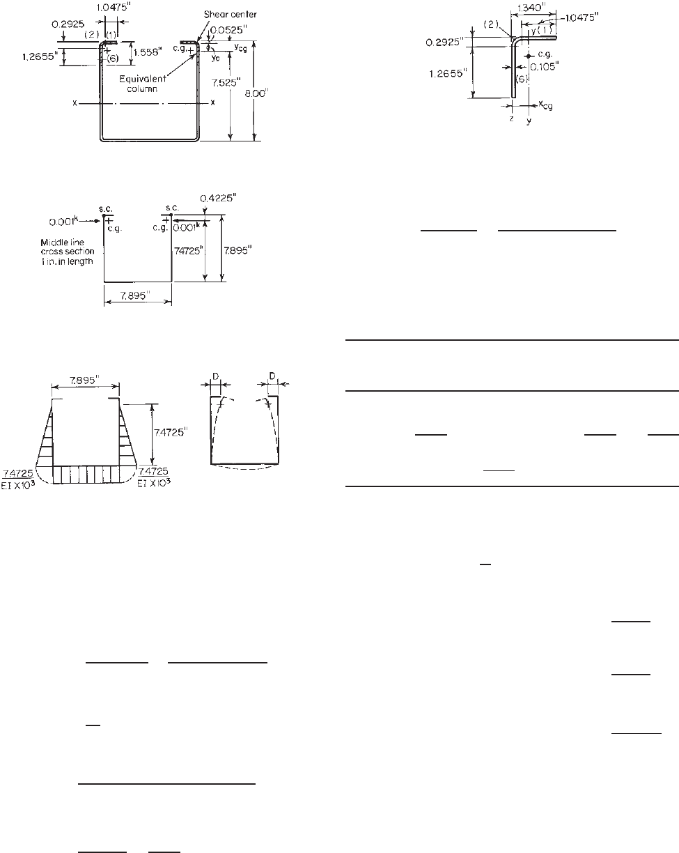
2. Determination of y
0
(Distance from Centroid of
Equivalent Column to Its Shear Center) (Fig. 4.38).
The centroid of the equivalent column can be located
as follows:
Distance from
Area A Top Fiber Ay
Element (in.
2
) y (in.) (in.
3
)
1 1.0475(0.105) = 0.1100 0.0525 0.0058
2 0.0396 (Table 4.1) = 0.0396 0.1373 0.0055
6 1.2655(0.105) =
0.1329 0.9253 0.1230
Total 0.2825 0.1343
y
cg
=
0.1343
0.2825
= 0.475 in.
From Appendix B it can be seen that the s hear center
of an angle section is located at the intersection of two
legs. Therefore, the distance y
0
between the centroid
and the shear center of the equivalent column is
y
0
= y
cg
−
1
2
t = 0.475 − 0.0525 = 0.4225 in
3. Calculation of Spring Constant β. The spring constant
β can be computed from Eq. (4.93) as
β =
0.001
D
BENDING STRENGTH AND DEFLECTION 139
Figure 4.38 Equivalent column.
Figure 4.39 Force applied to web for computing spring constant.
Figure 4.40 Lateral deflection of equivalent column.
for a portion of the member 1 in. in length. Here D
is the lateral deflection of the column centroid due
to a force of 0.001 kip applied to the web a t the
level of the column centroid (Fig. 4.39). Using the
moment–area method (Fig. 4.40), the deflection D can
be computed:
D =
(
7.4725
)
3
3EI × 10
3
+
(
7.4725
)
2
(
7.895
)
2EI × 10
3
where E = 29.5 × 10
3
ksi and
I =
1
12
(
0.105
)
3
= 96.5 × 10
−6
in.
4
Therefore
D =
359.50
29.5 × 10
3
96.5 × 10
−6
10
3
= 0.1263 in.
β =
1
D × 10
3
=
1
126.3
= 7.918 × 10
−3
Figure 4.41 Dimensions of equivalent column.
4. Computation of T
0
[Eq.(4.94)]
T
0
=
h
h + 3.4y
0
=
7.525
7.525 + 3.4
(
0.4225
)
= 0.840
5. Determination of P
cr
. In order to determine P
cr
,we
should first compute the moment of inertia of the
equivalent column about its y axis parallel to the web
(Fig. 4.41) as follows:
Distance from z
Area A Axis, Ax Ax
2
Element (in.
2
) x (in.) (in.
3
)(in.
4
)
1 0.1100 0.8163 0.0898 0.0733
2 0.0396 0.1373 0.0055 0.0008
6
0.1329 0.0525 0.0070 0.0004
Total 0.2825 0.1023 0.0745
x
cg
=
0.1023
0.2825
= 0.362 in.
The I values of the individual elements about their
own centroidal axes parallel to the web are
I
1
=
1
12
(
0.105
)(
1.0475
)
3
= 0.0101
I
2
= 0.0002
I
6
= 0.0000
I
1
+ I
2
+ I
6
= 0.0103
Ax
2
= 0.0745
I
z
= 0.0848 in.
4
−
A
x
2
cg
=−0.2825
(
0.362
)
2
=−0.0370
I
y
= 0.0478 in.
4
and
A = 0.2825 in.
2
Since the compression flange is braced at the third
points, the values of P
e
, C ,andL
can be computed
140 4 FLEXURAL MEMBERS
from Eqs. (4.95)–(4.97):
P
e
= 290,000
I
L
2
=
290,000
(
0.0478
)
48
2
= 6.016 kips
C =
βL
2
P
e
=
7.918 × 10
−3
(
48
)
2
6.016
= 3.032
L
= 3.7
4
I
h
t
3
= 3.7
4
0.0478
7.525
0.105
3
= 42.61 in.
Since C < 30 and L >L
, from Eq. (4.98),
P
cr
= T
0
P
e
1 +
βL
2
π
2
P
e
= 0.840
(
6.016
)
1 +
7.918 × 10
−3
(
48
)
2
π
2
(
6.016
)
= 0.840
(
6.016
)(
1 + 0.307
)
= 6.605 kips
6. Determination of (KL/r)
eq
. For the equivalent
column [Eq. (4.102)]
KL
r
eq
=
490
√
P
cr
/A
c
=
490
√
6.60/0.2825
= 101.3
7. Determination of Compression Stress F
n
.FromEq.
(5.56),
F
e
=
π
2
E
(
KL/r
)
2
eq
=
π
2
(
29,500
)
(
101.3
)
2
= 28.37 ksi
λ
c
=
F
y
F
e
=
33
28.37
= 1.08 < 1.5
F
n
=
0.658
λ
2
c
F
y
=
0.658
1.08
2
(
33
)
= 20.25 ksi
8. Design Compression Bending Stress [Eq. (4.103)]
F
b2
= 1.15F
n
C
c
y
c
= 1.15
(
20.25
)
4.812
4.337
= 25.84 ksi
<
F
y
= 33 ksi
OK
Once the design compression bending stress is computed,
the critical or nominal moment can be calculated as M
c
=
F
b2
S
c
.
In 1964, Haussler presented rigorous methods for deter-
mining the strength of elastically stabilized beams.
4.20
In his
methods, Haussler also treated the unbraced compression
flange as a column on an elastic foundation and maintained
more rigor in his development. A comparison of Haussler’s
method with Douty’s simplified method indicates that the
latter may provide a smaller critical stress.
In the early 1990s, the flexural behavior of standing seam
roof panels with laterally unsupported compression flanges
was restudied by Serrette and Pekoz.
4.158–4.162
Based on the
available test data and the analytical results from elastic
finite-strip buckling analysis, the authors introduced two
design methods in Ref. 4.161 to estimate the maximum
moment capacity of sections subjected to an interaction
between local and distortional buckling. It was assumed
that distortional buckling may be taken as local overall
buckling behavior. Both methods used the design philos-
ophy currently used in the North American Specification
for local–lateral buckling interaction. Method A used a
derived analytical expression for distortional buckling and
method B used a modified version of Douty’s formulation
discussed in this section. It was concluded that method A
gives somewhat better results than method B and is consis-
tent with the present formulation for flexural, torsional, and
torsional–flexural buckling.
According to the 2008 edition of the AISI Cold-Formed
Steel Design Manual, this type of buckling problem can
be solved by using the direct-strength method provided
in Appendix 1 of the North American Specification. For
this reason, the above 10-step design procedure has been
removed from the 2008 edition of the Design Manual.
4.2.4 Distortional Buckling Strength
The flexural strength of cold-formed steel beams bending
about the major axis may be limited by local buckling, or
lateral–torsional buckling. For members with edge-stiffened
flanges, the flexural strength may also be limited by distor-
tional buckling. As shown in Fig. 4.42, the local buck-
ling mode of a C-section for major-axis bending consists
of buckling of the compression portion of the web, the
compression flange, and edge stiffener without movement
of the line junction between the flange and edge stiff-
ener. For this type of limit state, the section strength
of the member is determined according to Section 4.2.2.
For the flange distortional buckling mode, the flange and
edge stiffener rotate about the flange–web junction with
some rotational resistance provided by the web. This
mode of failure occurs at considerably longer wavelengths
BENDING STRENGTH AND DEFLECTION 141
Figure 4.42 C-section purlin buckling stress versus half wavelength for major-axis bending.
1.69
than local buckling but generally shorter wavelength than
lateral–torsional buckling.
Distortional buckling may occur simultaneously with
local buckling.
1.358,4.208,4.223,4.224
Research work indicated
that the local–distortional interaction is generally weak
and that if this limit state is included in the design
requirements the resulting capacities are not consistent
with observations.
1.412
Therefore, no design provisions are
currently included in Appendix 1of the North American
Specification for this limit state. For detailed discussion
of modal interactions, see Section 13.4.4 of the SSRC
guide.
1.412
In earlier years, distortional buckling has not been
specifically considered for the design of cold-formed steel
members having edge-stiffened compression flanges. The
AISI design provisions provided by Desmond et al.
3.76
in
Section B4 of the specification account for the inability
of the stiffener to prevent flange buckling by reducing the
local buckling coefficient k to less than 4.0 for the partially
stiffened compression flange. The reduced buckling coeffi-
cient is then used to compute the effective width of the
flange element. However, in 1992 Kwon and Hancock
found that the AISI approach is unconservative for distor-
tional buckling of C-sections composed of high-strength
steel using a yield stress of 80 ksi (550 MPa or 5624
kg/cm
2
).
4.196
In 1999, Schafer and Pekoz indicated that the
AISI-reduced local buckling coefficient is only intended to
be used in conjunction with the specific effective width
expressions and is not actually the elastic buckling coeffi-
cient for distortional buckling.
1.412,3.226
In addition, the tests
conducted by Yu and Schafer s howed that the AISI effec-
tive width method is inadequate to account for distortional
buckling.
4.206,4.210
4.2.4.1 Research Work Since 1962, the distortional
buckling problem of cold-formed steel members has been
studied by Douty,
4.19
Haussler,
4.20
Desmond, Pekoz and
Winter,
3.76,3.77
Hancock,
1.69,4.163,4.164,1.358,4.223
Lim and
Rhodes,
4.293
Kwon and Hancock,
4.196
Hancock, Rogers,
and Schuster,
4.165
Lau and Hancock,
5.109–5.111
Serrette and
Pekoz,
4.158–4.162
Buhagiar, Chapman, and Dowling,
4.166
Davies and Jiang,
4.167,4.1.68,4.197
Schafer and Pekoz,
3.168,3.175,3.176,3.195
Bambach, Merrick, and Hancock,
3.173
Bernard, Bridge, and Hancock,
3.171,3.172
Ellifritt, Sputo,
and Haynes,
4.186
Kavanagh and Ellifritt,
4.188
Ellifritt,
Glover, and Hren,
4.169
Jonson,
4.198,4.199
Bradford,
4.200
Sarawit and Pekoz,
4.201
Camotim, Silvestre, and
Dinis,
4.202,4.203,4.207,4.208,4.214,4.225
Nuttayasakul and
Esterling,
4.204
Cortese and Murray,
4.205
Yu,
4.209
Yu
and Schafer,
4.206,4.210,4.217
Chodraui, Malite, Goncalves,
and Neto,
4.211,4.213
Schafer, Sarawit, and Pekoz,
4.212
Schafer and Adany,
4.215
Yap and Hancock,
4.216
Yu and
Lokie,
4.218
Javaroni and Goncalves,
4.219
Mahaarachchi and
Mahendran,
4.220
Georgescu,
4.221
Pham and Hancock,
4.222
Schafer, Sangree, and Guan,
4.223
Yap and Hancock,
4.226
Bambach,
4.227
and others. Some of the past research
findings and the development of the AISI design criteria
for distortional buckling strength of cold-formed steel
members are well summarized in the AISI commentary
1.346
and direct-strength method design guide.
1.383
Section
13.4.1 of the SSRC guide
1.412
presents detailed discussions
of the available research work on distortional buckling.
According to Section 13.2.3 of the SSRC Guide, Lau
and Hancock’s analytical model
5.109
is in widest use and
is based primarily on the assumption that the flange acts
as an isolated column undergoing flexural–torsional buck-
ling, while the web provides elastic restraint to the flange.

142 4 FLEXURAL MEMBERS
This model was subsequently improved to include more
consistent treatment of the web. Their model is used in
the Standards of A ustralia and New Zealand.
1.391
In 1999,
Schafer and Pekoz further developed the model to allow
for the impact of applied stresses on the web’s rotational
stiffness, thus allowing for the case when distortional buck-
ling is triggered by instability of the web as opposed to the
flange.
3.168
Schafer and Pekoz’s model is used in the North
American Specification.
1.345
4.2.4.2 North American Design Criteria for Distortional
Buckling Strength of Open-Section Flexural Members
In the North American Specification, Appendix 1 was
developed in 2004 for the use of the direct-strength method
to determine the structural strength of cold-formed steel
members by considering local buckling, distortional buck-
ling, and overall (global) buckling.
1.343
Subsequently, in
2007, a new Section C3.1.4 was added to the main
document of the North American Specification for deter-
mining the distortional buckling strength of I-, Z-, C-, and
other open cross-sectional flexural members having edge-
stiffened compression flanges.
1.345
For the convenience of readers, the following excerpts
are adapted from the 2007 edition of the North Amer-
ican Specification.
4.228
At the present time (2009), the
AISI Committee intends to move Section C3.1.4(a) to the
Commentary because it is for preliminary design and has
been specifically derived to always be more conservative
than Section C3.1.4(b).
C3.1.4 Distortional Buckling Strength [Resistance]
The provisions of Section C3.1.4 of the specification shall
apply to I-, Z-, C-, and other open cross-section members
that employ compression flanges with edge stiffeners, with
the exception of members that meet the criteria of Sections
4.2.5 and 4.2.6 w hen the R factor of Eq. (4.123) is employed
or Section 4.2.6.1. The nominal flexural strength [moment
resistance] shall be calculated in accordance with Eq. (4.104)
or Eq. (4.105). The safety factor and resistance factors given in
this section of the specification shall be used to determine the
allowable flexural strength or design flexural strength [factored
moment resistance] in accordance with the applicable design
method in Section 3.3.1, 3.3.2, or 3.3.3:
b
= 1.67 (ASD)
φ
b
=
0.90 (LRFD)
0.85 (LSD)
For λ
d
≤ 0.673
M
n
= M
y
(4.104)
For λ
d
> 0.673
M
n
=
1 − 0.22
M
crd
M
y
0.5
M
crd
M
y
0.5
M
y
(4.105)
where
λ
d
=
M
y
M
crd
(4.106)
M
y
= S
fy
F
y
(4.107)
where S
fy
is the elastic section modulus of full unreduced
section relative to the extreme fiber in the first yield and
M
crd
= S
f
F
d
(4.108)
where S
f
= elastic section modulus of full unreduced section
relative to extreme compression fiber
F
d
= elastic distortional buckling stress calculated in
accordance with either Section C3.1.4(a), (b), or
(c)
(a) Simplified Provision for Unrestrained C- and Z-Sections
with Simple Lip Stiffeners. For C- and Z-sections that have no
rotational restraint of the compression flange and are within the
dimensional limits provided in this section of the specification,
Eq. (4.109) shall be permitted to be used to calculate a
conservative prediction of the distortional buckling stress, F
d
.
See Section C3.1.4(b) or C3.1.4(c) for alternative provisions
and for members outside the dimensional limits of this section.
The following dimensional limits shall apply:
1. 50 ≤ h
o
/t ≤ 200,
2. 25 ≤ b
o
/t ≤ 100,
3. 6.25 < D /t ≤ 50,
4. 45
◦
≤ θ<90
◦
,
5. 2 ≤ h
o
/b
o
≤ 8, and
6. 0.04 ≤ D sinθ /b
o
≤ 0.5.
where h
o
=out-to-out web depth as defined in Fig. 3.30c
t = base steel thickness
b
o
= out-to-out flange width as d efined in Fig. 3.30c
D = out-to-out lip dimension as defined in Fig. 3.48
θ = lip angle as defined in Fig. 3.48
The distortional buckling stress F
d
shall be calculated as
follows:
F
d
= βk
d
π
2
E
12(1 − μ
2
)
t
b
o
2
(4.109)
where β, a value accounting for the moment gradient, which
is permitted to be conservatively taken as 1.0, is given as
β = 1.0 ≤ 1 + 0.4
L
L
m
0.7
1 +
M
1
M
2
0.7
≤ 1.3 (4.110)
where L is the minimum of L
cr
and L
m
:
L
cr
= 1.2h
o
b
o
Dsin θ
h
o
t
0.6
≤ 10h
o
(4.111)
L
m
is the distance between discrete restraints that restrict
distortional buckling (for continuously restrained members
L
m
= L
cr
); M
1
and M
2
are the smaller and the larger end
moments, respectively, in the unbraced segment (L
m
)ofthe
BENDING STRENGTH AND DEFLECTION 143
beam; M
1
/M
2
is positive when the moments cause reverse
curvature and negative when bent in single curvature;
k
d
= 0.5 ≤ 0.6
b
o
D sin θ
h
o
t
0.7
≤ 8.0 (4.112)
E is the modulus of elasticity; and μ is Poisson’s ratio.
(b) For C- and Z-Sections or any Open Section with a Stiffened
Compression Flange Extending to One Side of the Web Where
the Stiffener Is Either a Simple Lip or a Complex Edge Stiff-
ener. The provisions of this section of the Specification shall
be permitted to apply to any open section with a single web
and single edge-stiffened compression flange, including those
meeting the geometric limits of Section C3.1.4(a). The distor-
tional buckling stress F
d
shall be calculated in accordance with
Eq. (4.113) as follows:
F
d
= β
k
φfe
+ k
φwe
+ k
φ
˜
k
φfg
+
˜
k
φwg
(4.113)
where β, a value accounting for the moment gradient, which
is permitted to be conservatively taken as 1.0, is given as
β = 1.0 ≤ 1 + 0.4
L
L
m
0.7
1 +
M
1
M
2
0.7
≤ 1.3 (4.114)
where L is the minimum of L
cr
and L
m
:
L
cr
=
4π
4
h
o
(1 − μ
2
)
t
3
I
xf
(x
o
− h
x
)
2
+ C
wf
−
I
2
xyf
I
yf
(x
o
− h
x
)
2
+
π
4
h
4
o
720
1/4
(4.115)
where h
o
= out-to-out web depth as defined in Fig. 3.30 a
μ = Poisson’s ratio
t = base steel thickness
I
xf
= x-axis moment of inertia of flange
x
o
= x distance from flange/web juncti on to centroid
of flange
h
x
= x distance from centroid of flange to shear
centerofflange
C
wf
= warping torsion constant of flange
I
xyf
= product of moment of inertia of flange
I
yf
= y-axis moment of inertia of flange
In the above, I
xf
, I
yf
, I
xyf
, C
wf
, x
o
,andh
x
are properties o f
the compression flange plus edge stiffener about an x–y axis
system located at the centroid of the flange, with the x axis
measured positive to the right from the centroid and the y axis
positive down from the centroid.
The distance between discrete restraints that restrict distor-
tional buckling is given as L
m
(for continuously restrained
members L
m
= L
cr
)andM
1
and M
2
are the smaller and the
larger end moments, respectively, in the unbraced segment
(L
m
)ofthebeam;M
1
/M
2
is positive when the moments cause
reverse curvature and negative when bent in single curvature.
The elastic rotational stiffness provided by the flange to the
flange/web juncture is given as
k
φfe
=
π
L
4
EI
xf
(x
o
− h
x
)
2
+ EC
wf
− E
I
2
xyf
I
yf
(x
o
− h
x
)
2
+
π
L
2
GJ
f
(4.116)
where E = modulus of elasticity of steel
G = shear modulus
J
f
= St. Venant torsion constant of compression flange
plus edge stiffener about an x –y axis located at
centroid of flange with x axis measured positive
to the right from the centroid and y axis positive
down from the centroid
The elastic rotational stiffness provided by the web to the
flange/web juncture is given as
k
φwe
=
Et
3
12(1 − μ
2
)
3
h
o
+
π
L
2
19h
o
60
+
π
L
4
h
3
o
240
(4.117)
k
φ
is the rotational stiffness provided by a restraining element
(brace, panel, sheathing) to the flange/web juncture of a
member (zero if the compression flange is unrestrained); and
the geometric rotational stiffness (divided by the stress F
d
)
demanded by the flange from the flange/web juncture is
given as
˜
k
φfg
=
π
L
2
A
f
(
x
o
− h
x
)
2
I
xyf
I
yf
2
− 2y
o
(
x
o
− h
x
)
I
xyf
I
yf
+ h
2
x
+ y
2
o
+ I
xf
+ I
yf
(4.118)
where A
f
= cross-sectional area of compression flange plus
edge stiffener about x –y axis located at centroid
of flange, with x axis measured positive to the
right from the centroid and y axis positive down
from the centroid
y
o
= y distance from flange/web junction to centroid
of flange
The geometric rotational stiffness (divided by the stress F
d
)
demanded by the web from the flange/web juncture is given as
˜
k
φwg
=
h
o
tπ
2
13,440
⎛
⎜
⎜
⎜
⎝
[45,360(1 −ξ
web
) + 62,160]
(
L/h
o
)
2
+448π
2
+
(
h
o
/L
)
2
[53 + 3(1 −ξ
web
)]π
4
π
4
+ 28π
2
(
L/h
o
)
2
+ 420
(
L/h
o
)
4
⎞
⎟
⎟
⎟
⎠
(4.119)
where ξ
web
= (f
1
- f
2
)/f
1
, stress gradient in t he web, where
f
1
and f
2
are the stresses at the opposite ends of the web,
f
1
>f
2
, compression is positive, tension is negative, and the
stresses are calculated on the basis of the gross section (e.g.,
pure symmetrical bending, f
1
=-f
2
, ξ
web
= 2).
(c) Rational Elastic Buckling Analysis. A rational elastic buck-
ling analysis that considers distortional buckling shall be
144 4 FLEXURAL MEMBERS
permitted to be used in lieu of the expressions given in Section
C3.1.4(a) or (b). The safety and resistance factors in Section
C3.1.4 shal l apply.
In the above design criteria, Eqs. (4.104)–(4.107) are
based on Section 1.2.2.3 of Appendix 1 of the North Amer-
ican Specification. Good agreements are shown in Fig. 4.43
between the distortional buckling strength predictions and
the test data on commonly used C- and Z-sections in
bending.
1.346,4.210
Equation (4.108) is used to compute the critical elastic
distortional buckling moment, M
crd
. For the calculation of
the elastic distortional buckling s tress, f
d
, the following
three methods are given in the Specification:
1. Method (a) provides a simplified and conservative
prediction for C- and Z-sections with simple lip stiffeners
subjected to the given dimensional limits. For this approach,
the compression flange is assumed to be unrestrained.
2. Method (b) is for C- and Z-sections or any open section
with a stiffened compression flange extending to one side of
the web where the edge stiffener is either a simple lip or a
complex stiffener. This method considers elastic rotational
stiffnesses, rotational stiffness, and geometric rotational
stiffnesses.
For this method, design equations were derived by
Schafer and Pekoz.
3.168
The influence of the moment
gradient on distortional buckling was examined by Yu.
4.209
Since the design equations are complicated, the geometric
flange properties of C- a nd Z-sections can be computed
by using the equations provided in Table 4.4 based on the
midline dimentions and square corners.
3. Method (c) permits the use of a rational elastic buck-
ling analysis based on the principles of mechanics to
obtain an accurate prediction of elastic distortional buckling
strength. For example, the “finite-strip method” or “finite-
element method” can provide the solution as detailed in
the AISI commentary on Appendix 1 of the North Amer-
ican specification.
1.346
As discussed in Section 3.1.4 of the
Commentary on the 2007 edition of the North American
Specification, distortional buckling is unlikely to control the
strength of flexural member if (a) edge stiffeners are suffi-
ciently stiff to stabilize the flange, (b) unbraced lengths are
long and lateral–torsional strength limits the capacity, or (c)
adequate rotational restraint is provided to the compression
flange from attachments.
Example 4.13 illustrates the calculation of the nominal
flexural strength for distortional buckling based on Eq.
(4.105) using the elastic distortional buckling stresses deter-
minated by Sections C3.1.4(a) a nd C3.1.4(b) in the Speci-
fication.
Example 4.13 For the C-section used in Example 4.2,
determine the allowable moment for distortional buckling
according to ASD. Use the elastic distortional buckling
stresses based on the simplified provision of Section
C3.1.4(a) and the more precise provision of Section
C3.1.4(b) of the North American Specification.
Figure 4.43 Performance of distortional buckling prediction with test data on common C- and
Z-sections in bending.
1.346,4.210