Yu W., LaBoube R.A. Cold-Formed Steel Design
Подождите немного. Документ загружается.

BENDING STRENGTH AND DEFLECTION 145
Table 4.4 Geometric Flange Properties for C- and Z-Sections
1.346
For C-Sections For Z -Sections
A
f
= (b + d)t A
f
= (b + d)t
J
f
=
1
3
bt
3
+
1
3
dt
3
J
f
=
1
3
bt
3
+
1
3
dt
3
I
xf
=
t(t
2
b
2
+ 4bd
3
+ t
2
bd + d
4
)
12(b + d)
I
xf
=
t(t
2
b
2
+ 4bd
3
− 4bd
3
cos
2
(θ) + t
2
bd + d
4
− d
4
cos
2
(θ))
12(b + d)
I
yf
=
t(b
4
+ 4 db
3
)
12(b + d)
I
yf
=
t(b
4
+ 4 db
3
+ 6d
2
b
2
cos(θ) + 4d
3
b cos
2
(θ) + d
4
cos
2
(θ))
12(b + d)
I
xyf
=
tb
2
d
2
4(b + d)
I
xyf
=
tbd
2
sin(θ)[b + d cos(θ)]
4(b + d)
C
wf
= 0 C
wf
= 0
x
0
=
b
2
2(b + d)
x
0
=
b
2
− d
2
cos(θ)
2(b + d)
h
x
=
−(b
2
+ 2 db)
2(b + d)
h
x
=
−[b
2
+ 2 db + d
2
cos(θ)]
2(b + d)
h
y
= y
0
=
−d
2
2(b + d)
h
y
= y
0
=
−d
2
sin(θ)
2(b + d)
SOLUTION
A. Distortional Buckling Strength Based on Section
C3.1.4(a).
In order to use Section C3.14(a) of the Specification for
computing the elastic distortional buckling stress, F
d
,the
following geometric limits should be checked as the first
step:
1. 50 <(h
o
/t = 133.33)<200 OK
2. 25 <(b
o
/t = 46.67)<100 OK
3. 6.25 <(D/t = 9.6)<50 OK
4. 45
◦
<(θ= 90
◦
) = 90
◦
OK
5. 2 <(h
o
/b
o
= 2.86)<8OK
6. 0.04 <(Dsin θ/b
o
= 0.21)<0.5OK
From Eq. (4.109), the elastic distortional buckling stress
is calculated a s follows:
F
d
= βk
d
π
2
E
12(1 − μ
2
)
t
b
o
2
Based on Eq. (4.112), the plate buckling coefficient for
distortional buckling is
k
d
= 0.6
b
o
D sin θ
h
o
t
0.7
= 0.6
3.5(0.72) sin 90
◦
10(0.075)
0.7
= 1.40
Since 0.5 <k
d
< 8, use k
d
= 1.40. Because M
1
and M
2
are not given in the problem, use β = 1.0 as a conservative
value. Therefore,
F
d
= (1)(1.40)
π
2
(29,500)
12(1 − 0.3
2
)
0.075
3.50
2
= 17.14 ksi
Based on the full unreduced section and using the design
procedure shown earlier, the elastic modulus relative to the
extreme compression fiber is
S
f
= 4.11 in.
3
The critical elastic distortional buckling moment [(Eq.
(4.108)] is
M
crd
= S
f
F
d
= (4.11)(17.14) = 70.45 in.-kips
146 4 FLEXURAL MEMBERS
The yield moment [(Eq. 4.107)] is
M
y
= S
fy
F
y
= S
f
F
y
= (4.11)(50) = 205.50 in.-kips
The slenderness factor for distortional buckling [(Eq.
4.106)] is
λ
d
=
M
y
M
crd
=
205.50
70.45
= 1.71
Since λ
d
> 0.673, the nominal moment for distortional
buckling can be computed according to Eq. (4.105) as
follows:
M
nd
=
1 − 0.22
M
crd
M
y
0.5
M
crd
M
y
0.5
M
y
=
1 − 0.22
70.45
205.50
0.5
70.45
205.50
0.5
(205.50)
= 104.82 in.-kips
Based on ASD, the allowable moment for distortional
buckling according to Section C3.1.4(a) is
M
a
=
M
nd
b
=
104.82
1.67
= 62.77 in.-kips
B. Distortional Buckling Strength Based on Section
C3.1.4(b).
Based on the equations listed in Table 4.4, the geometric
flange properties for the C-section can be computed as
follows. The reason for these calculations is that the
mechanical model for prediction of distortional buckling
strength considers the flange itself as a “column”which
may undergo restrained flexural–torsional buckling, and the
restraint comes from the web and any additional attach-
ments. It should be noted that in the following equations, the
symbols x
o
and y
o
are presented as x
of
and y
of
, respectively,
to prevent confusions with other sections of the specifica-
tion:
h = h
0
− t = 10.000 − 0.075 = 9.925 in.
b = b
0
− t = 3.500 − 0.075 = 3.425 in.
d = D − t/2 = 0.720 −0.075/2 = 0.6825 in.
A
f
= (b + d)t = (3.425 +0.6825)(0.075) = 0.308 in.
2
I
xf
= t[t
2
b
2
+ 4bd
3
+ t
2
bd + d
4
]/12(b + d)
= (0.075)[(0.075)
2
(3.425)
2
+ 4(3.425)(0.6825)
3
+ (0.075)
2
(3.425)(0.6825)
+ (0.6825)
4
]/12(3.425 + 0.6825) = 0.00708 in.
4
I
yf
= t[b
4
+ 4bd
3
]/12(b + d)
= (0.075)[(3.425)
4
+ 4(0.6825)(3.425)
3
]
/12(3.425 + 0.6825)
= 0.376 in
4
.
I
xyf
= tb
2
d
2
/4(b + d)
= (0.075)(3.425)
2
(0.6825)
2
/4(3.425 + 0.6825)
= 0.0249 in
4
.
x
0f
= b
2
/2(b + d) = (3.425)
2
/2(3.425 + 0.6825)
= 1.428 in.
y
0f
=−d
2
/2(b + d) =−(0.6825)
2
/2(3.425 + 0.6825)
=−0.0567 in.
h
x
=−[b
2
+ 2db]/2(b + d)
=−[(3.425)
2
+ 2(0.6825)(3.425)]/2(3.425 + 0.6825)
=−1.997 in.
J
f
= [bt
3
+ dt
3
]/3
= [(3.425)(0.075)
3
+ (0.6825)(0.075)
3
]/3
= 0.000578 in
4
.
C
wf
= 0.0in.
6
According to Eq. (4.115), the critical unbraced length of
distortional buckling, L
cr
, can be computed as follows:
L
cr
=
4π
4
h
0
(1 − μ
2
)
t
3
I
xf
(x
0f
− h
x
)
2
+ C
wf
−
I
2
xyf
I
yf
(x
0f
− h
x
)
2
+
π
4
h
4
0
720
'
1/4
=
4π
4
(10.000)(1 − 0.3
2
)
(0.075)
3
0.00708[1.428
− (−1.997)]
2
+ 0 −
(0.0249)
2
0.376
×[1.428 − (−1.997)
2
]
+
π
4
(10.000)
4
720
1/4
= 27.07 in.
Assume that the distortional buckling length L equals L
cr
,
L = L
cr
= 27.07 in.
BENDING STRENGTH AND DEFLECTION 147
From Eq. (4.116), the elastic rotational s tiffness provided
by the flange to the flange/web juncture, k
φfe
,is
k
φfe
=
π
L
4
EI
xf
(x
0f
− h
x
)
2
+ EC
wf
− E
I
2
xyf
I
yf
(x
0f
− h
x
)
2
+
π
L
2
GJ
=
π
27.07
4
(29,500)(0.00708)[1.428 − (−1.997)]
2
+ (29,500)(0.0) − (29,500)
(0.0249)
2
0.376
[1.428
− (−1.997)]
2
+
π
27.07
2
(11,300)(0.000578)
= 0.429 in.-kips/in.
From Eq. (4.117), the elastic rotational s tiffness provided
by the web to the flange/web juncture, k
φfe
,is
k
φwe
=
Et
3
12(1 − μ
2
)
3
h
0
+
π
L
2
19h
0
60
+
π
L
4
h
3
0
240
=
(29,500)(0.075)
3
12[1 − (0.3)
2
]
3
10.000
+
π
27.07
2
(19)(10.000)
60
+
π
27.07
4
(10.000)
3
240
= 0.391 in.-kips/in.
From Eq. (4.118), the geometric rotational stiffness
demanded by the flange from the flange/web juncture,
˜
k
φfg
,
is
˜
k
φfg
=
π
L
2
A
f
(
x
of
− h
x
)
2
I
xyf
I
yf
2
− 2y
of
(
x
of
− h
x
)
I
xyf
I
yf
+ h
2
x
+ y
2
of
+ I
xf
+ I
yf
=
π
27.07
2
(0.308)
[1.428 − (−1.997)]
2
×
0.0249
0.376
2
− 2
(
−0.0567
)
[1.428 − (−1.997)]
×
0.0249
0.376
+ (−1.997)
2
+ (−0.0567)
2
+ 0.00708 + 0.376
= 0.0220 (in.-kips/in.)/ksi
From Eq. (4.119), the geometric rotational stiffness
demanded by the web from the flange/web juncture,
˜
k
φwg
˜
k
φwg
=
h
o
tπ
2
13,440
×
⎛
⎜
⎜
⎜
⎝
[45,360(1 − ξ
web
) + 62,160]
(
L/h
o
)
2
+448π
2
+
(
h
o
/L
)
2
[53 +3(1 − ξ
web
)]π
4
π
4
+ 28π
2
(
L/h
o
)
2
+ 420
(
L/h
o
)
4
⎞
⎟
⎟
⎟
⎠
=
(10.000)(0.075)π
2
13,440
×
⎛
⎜
⎜
⎜
⎝
[45,360(1 − 2) + 62,160]
(
27.07/10.000
)
2
+448π
2
+
(
10.000/27.07
)
2
[53 + 3(1 − 2)]π
4
π
4
+ 28π
2
(
27.07/10.000
)
2
+ 420
(
27.07/10.000
)
4
⎞
⎟
⎟
⎟
⎠
= 0.00286 (in.-kips/in.)/ksi
From Eq. (4.113), the elastic distortional buckling stress
F
d
is
F
d
= β
k
φfe
+ k
φwe
+ k
φ
˜
k
φfg
+
˜
k
φwg
In the above equation, use β = 1.0 as a conservative value
(i.e., ignoring moment gradient). Since no sheathing is
attached to the beam, k
φ
= 0. Therefore,
F
d
= 1.0
0.429 + 0.391 + 0.0
0.0220 + 0.00286
= 32.98 ksi
which is 92% higher than the elastic distortional buckling
stress computed in item A above using the simplified provi-
sion on the basis of Section C3.1.4(a) of the specification.
From item A, S
f
= 4.11 in.
3
Based on Eq. (4.108), the crit-
ical elastic distortional buckling moment, M
crd
,is
M
crd
= S
f
F
d
= (4.11)(32.98) = 135.55 in.-kips
Also from item A, M
y
= 205.50 in.-kips. The slenderness
factor for distortional buckling [Eq. (4.106)] is
λ
d
=
M
y
M
crd
=
205.50
135.55
= 1.231 > 0.673
The nominal moment for distortional buckling according to
Eq. (4.105) is
M
nd
=
1 − 0.22
M
crd
M
y
0.5
M
crd
M
y
0.5
M
y
=
1 − 0.22
135.55
205.50
0.5
135.55
205.50
0.5
(205.50)
= 137.08 in.-kips

148 4 FLEXURAL MEMBERS
Based on ASD, the allowable moment for distortional
buckling according to Section C3.1.4 (b)is
M
a
=
137.08
1.67
= 82.08 in.-kips
It is noted that Section C3.1.4 (b) provides 31% higher
moment than the conservative Section C3.1.4 (a) of the
North American Specification and is used for design.
It can be seen that the above allowable moment for
distortional buckling based on Section C3.1.4(b) of the
Specification is smaller than the allowable moment for
section strength of 96.14 in.-kips computed in Example 4.2.
If Section C3.1.4(c) is used, a similar difference could be
obtained. See Chapter 15 for using Section C3.1.4(c) of the
Specification. Example II-4 of the 2008 edition of the AISI
Design Manual illustrates the use of Sections C3.1.4(a), (b),
and (c) for distortional buckling of the C-section. For design
purpose, it is appropriate to use either Section C3.1.4(b)
or (c) of the specification. In Tables II-7, II-8, a nd II-
9 of the AISI Design Manual, the computed distortional
buckling properties are provided for the representative C-
shapes, SSMA studs, and Z-shapes with lips, respectively.
The values in these tables have been calculated for use with
Section C3.1.4(b) of the Specification.
4.2.5 Beams Having One Flange Through Fastened
to Deck or Sheathing
When roof purlins or wall girts are subject to the suction
force due to wind load, the compression flange of the
member is laterally unbraced, but the tension flange is
supported by the deck or sheathing. The bending capacity
of this type of flexural member is less than the fully braced
member but is greater than the laterally unbraced condition
because of the rotational restraint provided by the panel-
to-purlin (or girt) connection. The rotational stiffness has
been found to be a function of the member thickness, sheet
thickness, fastener type, and fastener location.
In the past, the bending capacity of flexural members
having the tension flange through-fastened to deck or
sheathing has been studied by a large number of inves-
tigators in various countries.
4.30–4.40
Based on the results
of these studies, reduction factors for the effective yield
moment have been developed for simple- a nd continuous-
span conditions. These factors are given in Section D6.1.1
of the 2007 edition of the North American Specification.
It should be noted that the R factors for simple-span
C- and Z-sections up to 8.50 in. (216 mm) in depth have
been increased from the 1986 AISI Specification based on
Fisher’s study (Ref. 4.170). In view of the fact that these
reduction factors were based on the available experimental
data, their use for design is limited only to the conditions
listed in the Specification. For the convenience of readers,
the following excerpts are adapted from the North American
Specification:
D6.1.1 Flexural Members Having One Flange Through
Fastened to Deck or Sheathing
Section D6.1.1 of the specification shall not apply to a contin-
uous beam for the region between inflection points adjacent to
a support, or to a cantilever beam.
The nominal flexural strength [moment resistance], M
n
,of
a C- or Z-section loaded in a plane parallel to the web, with
the tension flange attached to deck or sheat hing and wit h the
compression flange laterally unbraced shall be calculated in
accordance with Eq. (4.120). The safety factor and resistance
factors given in this section of the Specification shall be used
to determine the allowable flexural strength or d esign flexural
strength [factored moment resistance] in accordance with the
applicable design method in Sections 3.3.1, 3.3.2, or 3.3.3.
M
n
= RS
e
F
y
(4.120)
b
= 1.67 (ASD)
φ
b
=
0.90 (LRFD)
0.90 (LSD)
where R is obtained from Table D6.1.1-1 for simple-span C- or
Z-sections and R equals 0.60 for continuous-span C-sections
and 0.70 for continuous-span Z-sections. The values S
e
and F
y
are as defined in Section 4.2.2.1.
The reduction factor, R, shall be limited to roof and wall
systems meeting the following conditions:
1. Member depth less than 11.5 in. (292 mm).
2. Member flanges with edge stiffeners.
3. 60 ≤ depth/thickness ≤170.
4. 2.8 ≤ depth/flange width ≤4.5.
5. 16 ≤ flat width/thickness of flange ≤43.
6. For continuous-span systems, the lap length at each
interior support in each direction (distance from center
of support to end of lap) is not less than 1.5d .
7. Member span length is not greater than 33 ft (10 m).
8. Both flanges are prevented from moving laterally at the
supports.
9. Roof or wall panels are steel sheets with 50 ksi (345 MPa
or 3520 kg/cm
2
) minimum yield stress and a minimum
of 0.018 in. (0.46 mm) base metal thickness, having a
minimum rib depth of 1
1
8
in. (29 mm), spaced a maximum
Table D6.1.1-1 Simple Span C- or Z-Section R Values
Depth Range, in. (mm) Profile R
d ≤ 6.5 (165) C or Z 0.70
6.5 (165) < d ≤ 8.5 (216) C or Z 0.65
8.5 (216) < d ≤ 11.5 (292) Z 0.50
8.5 (216) < d ≤ 11.5 (292) C 0.40

BENDING STRENGTH AND DEFLECTION 149
of 12 in. (305 mm) on centers and attached in a manner to
effectively inhibit relative movement between the panel
and purlin flange.
10. Insulation is g lass fiber blanket 0 to 6 in. (152 mm) thick
compressed between the member and panel in a manner
consistent with the fastener being used.
11. Fastener type is, at minimum, No. 12 self-drilling or self-
tapping sheet metal screws or
3
16
-in. (4.76-mm) rivets,
having washers
1
2
in. (12.7 mm) diameter.
12. Fasteners is not standoff t ype screws.
13. Fasteners are spaced not greater than 12 in. (305 mm) on
centers and placed near the center of the beam flange,
and adjacent to the panel high rib.
14. The design yi el d stress of the member does not exceed
60 ksi (410 MPa or 4220 kg/cm
2
).
If variables fall outside any of the above-stated limits, the
user shall perform full-scale tests in accordance with Section
F1 of this Specification or apply a rational analysis procedure.
For continous purlin systems in which adjacent bay span
lengths vary by more than 20 percent, the R values for the
adjacent bays shall be taken from Table D6.1.1-1. The user
shall be permitted to perform tests in accordance with Section
Fl as an alternate to the procedure described in this section of
the Specification.
For simple-span members, R shall be reduced for the
effects of compressed insulation between the sheeting and the
member. The reduction shall be calculated by multiplying R
from Table D6.1.1-1 by the following correction factor, r.
r =
(
1.00 − 0.01t
i
when t
i
is in inches (4.121)
1.00 − 0.0004t
i
when t
i
is in millimeters (4.122)
where t
i
is the thickness of uncompressed glass fiber blanket
insulation.
4.2.6 Flexural Members Having One Flange Fastened
to a Standing Seam Roof System
Standing seam roofs were first introduced in the 1930s.
4.171
Because standing seam roof panels are attached to
supporting purlins with a clip that is concealed in the
seam, this type of roof system has proved to be a
cost-effective roof membrane due to its superior weather
tightness, its ability to provide consistent thermal perfor-
mance, its low maintenance requirements, as well as its
ability to adjust to thermal expansion and contraction.
4.172
For C- or Z-purlins supporting a standing seam roof
system, the bending capacity is greater than the bending
strength of an unbraced member and may be equal to the
bending strength of a fully braced member. The bending
capacity is governed by the nature of the loading, gravity
or uplift, and the nature of the particular standing seam
roof system. Due to the availability of numerous types
of standing seam roof systems, an analytical method for
computing positive and negative bending capacities has not
been developed. Consequently, Section C3.1.4 was added
in the 1996 edition of the AISI Specification and is retained
in Appendix A of the 2007 edition of the North American
Specification as Section D6.1.2 for beams having one flange
fastened to a standing seam roof system. In this section,
it is specified that the available flexural strength of a C-
or Z-section loaded in a plane parallel to the web with
the top flange supporting a standing seam roof system
shall be determined using discrete point bracing and the
provisions of Section C3.1.2.1 of the Specification or shall
be calculated as follows:
M
n
= RS
e
F
y
(4.123)
b
= 1.67 (ASD)
φ
b
= 0.90 (LRFD)
where R is the reduction factor determined in accordance
with AISI S908 and S
e
and F
y
are defined in Section
4.2.2.1. For additional design information, see Ref. 4.172,
which includes detailed discussion and design examples
using standing seam roof systems. The major advantage
of the base test is that a simple span test may be used
to predict the performance of continuous-span systems for
reducing experimental costs. The concepts for the base
test was developed by T. M. Murray and his associates
at Virginia Polytechnic Institute & State University.
In Canada, this type of member is designed in accordance
with the bracing requirements given in Section D3.2.2 of
Appendix B in the 2007 edition of the North American
Specification.
4.2.6.1 Strength of Standing Seam Roof Panel System
Under gravity loading, the nominal strength of standing
seam roof panel systems can be determined according
to Chapters B and C of the Specification because the
load-carrying capacity of usual panels can be calculated
accurately. The strength of this type of panel system can
also be determined by the AISI Test Procedure S906,
Standard Procedures for Panel and Anchor Structural Tests,
in accordance with Section D6.2.1 of the North American
Specification.
1.345
For uplift loading, the nominal strength of standing seam
roof panels and their attachments or anchors cannot be
calculated with accuracy; therefore, it can only be deter-
mined by tests using the AISI Test Procedure S906 with the
requirements and exceptions prescribed in Section D6.2.1
of the Specification on the use of Factory Mutual FM4471,
Corps of Enginners CEGS 07416, and ASTM E1592. The
load combinations including wind uplift are provided in
Section D6.2.1a of Appendix A of the Specification.
150 4 FLEXURAL MEMBERS
The evaluation of test results should follow the AISI
Standard Procedure S906 included in the AISI Cold-
Formed Steel Design Manual.
1.349
When three or more
assemblies are tested, safety factors (not less than 1.67)
and resistance factors (not greater than 0.9) shall be deter-
mined in accordance with the procedure of Section F1.1 (b)
with the target reliability index and statistical data provided
in Section D6.2.1 of the Specification. The justifications for
these variables are discussed in the AISI Commentary.
1.346
When the number of physical test assemblies is less than 3,
a safety factor of 2.0 and resistance factors of 0.8 (LRFD)
and 0.7 (LSD) shall be used.
4.2.7 Unusually Wide Beam Flanges and Unusually
Short Span Beams
When beam flanges are unusually wide, special consid-
eration should be given to the possible effects of shear
lag and flange curling, even if the beam flanges, such as
tension flanges, do not buckle. Shear lag depends on the
type of loading and the span-to-width ratio and is indepen-
dent of the thickness. Flange curling is independent of span
length but depends on the thickness and width of the flange,
the depth of the section, and the bending stresses in both
flanges.
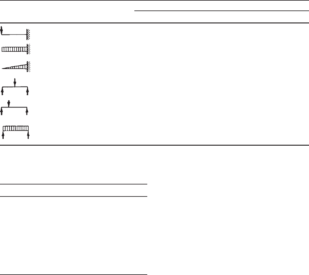
4.2.7.1 Shear Lag For conventional structural members
with ordinary dimensions, the effect of shear deformation
on flange stress distribution is negligible. H owever, if
the flange of a beam is unusually wide relative to its
span length, the effect of shear deformation on bending
stress is pronounced. As a result, the bending stresses in
both compression and tension flanges are nonuniform and
decrease with increasing distance from the web, as shown
in Fig. 4.44 for a box-type beam and an I-section. This
phenomenon is known as shear lag.
Analytical and experimental investigations of the
problem on shear lag have previously been conducted by
Hildebrand and Reissner,
4.41
Winter,
4.42
Miller,
4.43
and
Tate.
4.44,4.45
This subject has been investigated by Malcolm
Figure 4.44 Stress distribution in both compression and tension
flanges of beams due to shear lag.
Figure 4.45 Analytical curve for determining effective width of
flange of short-span beams.
4.42
and Redwood,
4.46
Parr and Maggard,
4.47
Van Dalen and
Narasimham,
4.48
and Lamas and Dowling
4.49
and in Refs.
4.50–4.55.
In their paper, Hildebrand and Reissner concluded that
the amount of shear lag depends not only on the method
of loading and support and the ratio of span to flange
width but also on the ratio of G /E and the ratio m =
(3I
w
+ I
s
)/(I
w
+ I
s
),whereI
w
and I
s
are the moments of
inertia of webs and of cover plates, respectively, about the
neutral axis of the beam.
Based on the theory of plane stress, Winter analyzed
the shear lag problem and developed tabular and graphic
data,
4.42
from which the effective width of any given beam
section can be obtained directly for use in design. The ratios
of the maximum and minimum bending stresses in beam
flanges were computed and verified by the results of 11 I-
beam tests. It was indicated that shear lag is important for
beams with wide flanges subjected to concentrated loads
on fairly short spans; the smaller the span-to-width ratio,
the larger the effect. For beams supporting uniform loads,
shear lag is usually negligible except that the L/w
f
ratio
is less than about 10 as shown in Fig. 4.45. Winter also
concluded that for a given span-to-width ratio the effect of
shear lag is practically the same for box beams, I-beams,
T-beams, and U-shaped beams.
Table 4.5 is a summary of the ratios of effective design
width to actual width based on the results obtained by
several investigators.
4.45
In Table 4.5, w
f
is the width of the flange projec-
tion beyond the web for I-beams and half the distance
between webs for multiple-web sections (Fig. 4.44); L is
the span length. It should be noted that the values obtained
by Hildebrand and Reissner were for G/E = 0.375 and
m = 2.
As far as the design criteria are concerned, the “effective
width” concept used in the design of compression elements
BENDING STRENGTH AND DEFLECTION 151
Table 4.5 Ratio of Effective Design Width to Actual Width for Wide Flanges
L/w
f
Loading Condition Investigator 6 8 10 12 16 20 30
Hildebrand and Reissner 0.830 0.870 0.895 0.913 0.934 0.946
Hildebrand and Reissner 0.724 0.780 0.815 0.842 0.876 0.899
Hildebrand and Reissner 0.650 0.710 0.751 0.784 0.826 0.858
Hildebrand and Reissner 0.686 0.757 0.801 0.830 0.870 0.895 0.936
Winter 0.550 0.670 0.732 0.779 0.850 0.894 0.945
Miller — — 0.750
Hildebrand and Reisser 0.610 0.686 0.740 0.778 0.826 0.855 0.910
Hiildebrand and Reisser 0.830 0.897 0.936 0.957 0.977 0.985 0.991
Winter 0.850 0.896 0.928 0.950 0.974 0.984 0.995
Miller — — 0.875
Table 4.6 Maximum Allowable Ratio of Effective
Design Width to Actual Width for Short-Span,
Wide Flanges
L/w
f
Effective Design Width/Actual Width
30 1.00
25 0.96
20 0.91
18 0.89
16 0.86
14 0.82
12 0.78
10 0.73
80.67
60.55
(Section 3.5) can also be applied to the design of beams
whenever the shear lag problem is critical.
Based on the results of Winter’s investigation,
4.42
design
provisions for s hear lag have been developed as included in
Section B1.1(c) of the North American Specification.
1.345
It is specified that when the effective span L of the beam
is less than 30w
f
and when it carries one concentrated load
or several loads spaced farther apart than 2w
f
, the ratio of
effective design width to actual width of the tension and
compression flanges shall be limited to the value given in
Table 4.6 in accordance with the L/w
f
ratio.
In the application of Table 4.6 the effective span length
of the beam is the full span for simple-span beams, the
distance between inflection points for continuous beams,
or twice the length of cantilever beams. The symbol w
f
indicates the width of the flange projection beyond the
web for I-beams a nd similar sections or half the distance
between webs for multiple-web sections, including box or
U-type sections (Fig. 4.44). When I-beams and similar
sections are stiffened by lips at outer edges, w
f
shall be
taken as the sum of the flange projection beyond the web
plus the depth of the lip.
The tabulated ratios in Table 4.6 are also plotted in
Fig. 4.45 for comparison with the analytical values. The
AISI design values are slightly larger than the analytical
results when L/w
f
ratios exceed about 16.
Although the a bove-discussed provision relative to shear
lag is applicable to tension and compression flanges, local
buckling in compression as discussed in Section 3.5 may be
a critical factor and should also be investigated separately.
The shear lag problem is of particular importance in the
analysis and design of aircraft and naval structures. In cold-
formed steel building construction, however, it is infrequent
that beams are so wide that they would require considerable
reduction of flange widths.
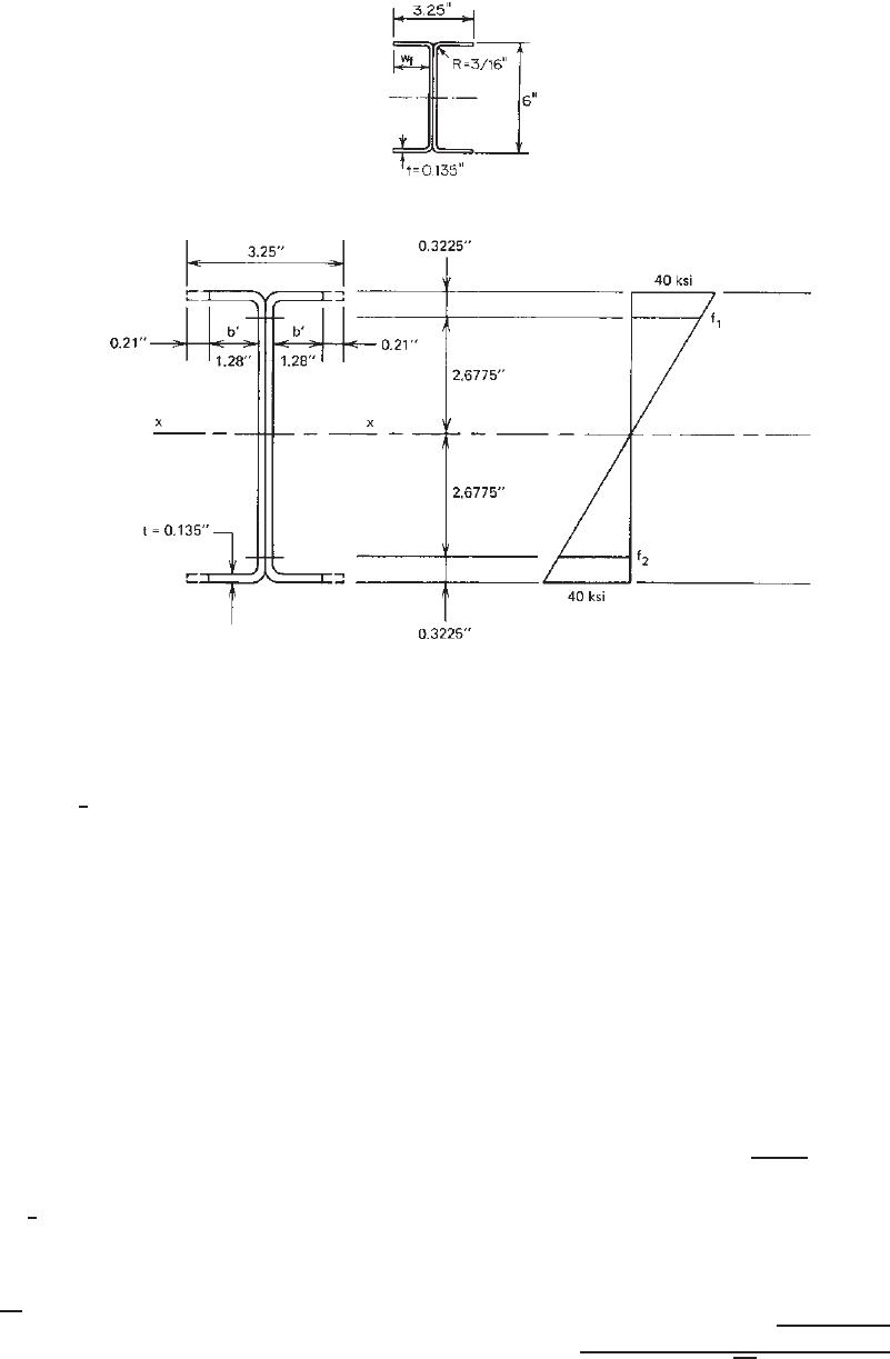
Example 4.14 Compute the nominal moment for the
beam section shown in Fig. 4.46a if it is used to support
a concentrated load on a simple span of 2 ft. Assume that
the minimum yield stress of steel is 40 ksi.
152 4 FLEXURAL MEMBERS
(a)
(b)
Figure 4.46 Example 4.14.
SOLUTION. From Fig. 4.46a,
w
f
=
1
2
(
3.25
)
− 0.135 = 1.490 in.
30w
f
= 44.70 in.
L = 2ft= 24 in.
Since L<30w
f
and the beam is subject to a concentrated
load, shear lag is an important factor.
Using Table 4.6 for L/w
f
= 16.1, the ratio of effective
design width to actual width is 0.86. The effective design
widths for both compression and tension flanges are
b
= 0.86 × 1.49 = 1.28 in.
See Fig. 4.46b.
To check if the web is fully effective according to Section
3.5.1.2,
f
1
= 40
1
3
× 2.6775
= 35.7ksi
(
compression
)
f
2
= 35.7ksi
(
tension
)
=
f
2
f
1
= 1.0
k = 4 + 2[1 + 1]
3
+ 2[1 + 1] = 24
From Fig 4.46a,
h
0
= out-to-out depth of web
= 6.00 in.
b
0
= out-to-out width of the
compression flange of each channel
= 3.25/2
= 1.625 in.
Since h
0
/b
0
= 3.69 < 4, then use Eq. (3.55a),
b
1
=
b
e
3 + ψ
where b
e
is the effective width of the web determined in
accordance with Eqs. (3.41)–(3.44) with f
1
substistuted for
f and k = 24 as follows:
λ =
1.052(5.355/0.135)
√
35.7/29,500
√
24
= 0.296
BENDING STRENGTH AND DEFLECTION 153
Since λ<0.673, ρ = 1.0,
b
e
= 5.355 in.
b
1
=
b
e
3 + ψ
=
5.355
3 + 1
= 1.339 in.
For ψ = 1, which is larger than 0.236,
b
2
=
1
2
b
e
=
1
2
× 5.355 = 2.678 in.
b
1
+ b
2
= 1.339 + 2.678 = 4.017 in.
Since b
1
+ b
2
is larger than the compression portion of the
web of 2.6775 in., the web is fully effective.
Based on the method discussed previously, the effective
section modulus is
S
e
= 3.4in.
3
The nominal moment is
M
n
= S
e
F
y
= 3.4 × 40 = 136 in.-kips
The nominal moment determined above for shear lag
should be checked for local buckling. Since w =
1
2
(3.25) −
(0.1875 + 0.135) = 1.3025 in.,
w
t
=
1.3025
0.135
= 9.62
λ =
1.052
√
0.43
(9.62)
40
29,500
= 0.568 < 0.673
b = w = 1.3025 in.
The nominal moment is
M
n
= S
x
(full section)(40)
In view of the fact that the nominal moment determined
above for local buckling consideration is larger than that
determined for shear lag, the nominal moment of 136 in.-
kips will govern the design.
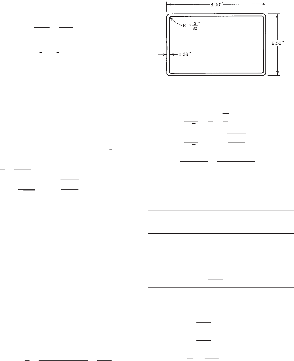
Example 4.15 For the tubular section shown in Fig. 4.47,
determine the nominal moment if the member is to be
used as a simply supported beam to carry a concentrated
load at midspan. Assume that the span length is 5 ft and
F
y
= 50 ksi.
SOLUTION
1. Nominal Moment Based on Effective Width of
Compression Flange. For the compression flange,
w
t
=
8 − 2
(
3/32 + 0.06
)
0.06
=
7.693
0.06
= 128.2
Figure 4.47 Example 4 .15.
Based on Eqs. (3.41)–(3.44),
λ =
1.052
√
k
w
t
f
E
=
1.052
√
4
(128.2)
50
29,500
= 2.776 > 0.673
ρ =
1 − 0.22/λ
λ
=
1 − 0.22/2.776
2.776
= 0.332
b = ρw = 0.332(7.693) = 2.554 in.
See Fig. 4.48a.
Assume that the web is fully effective. The distance
y
cg
can be determined as follows:
Distance from
Area A Top Fiber Ay Ay
2
Element (in.
2
) y (in.) (in.
3
)(in.
4
)
1 2.554 × 0.06 = 0.1532 0.030 0.0046 0.00014
22× 0.01166 = 0.0233 0.073 0.0017 0.0013
32× 4.6925 × 0.06 = 0.5631 2.500 1.4078 3.5194
42× 0.01166 = 0.0233 4.927 0.1148 0.5656
5 7.6925 × 0.06 =
0.4616 4.970 2.2942 11.4019
Total 1.2245 3.8231 15.48717
y
cg
=
(Ay)
A
= 3.122 in.
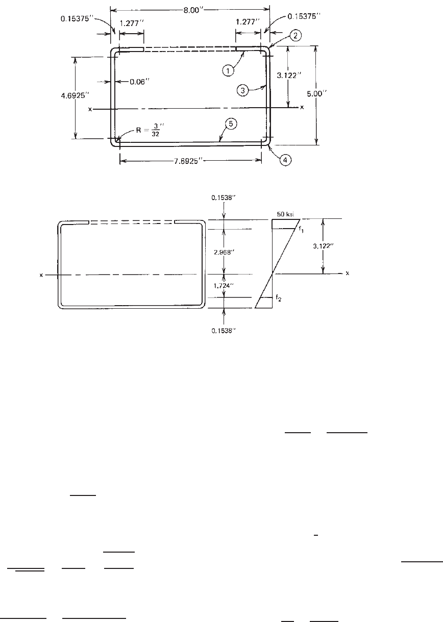
1. To check if the web is fully effective (see
Fig. 4.48b),
f
1
= 50
2.968
3.122
= 47.53 ksi (compression)
f
2
= 50
1.724
3.122
= 27.61 ksi (tension)
ψ =
f
2
f
1
=
27.61
47.53
= 0.581
k = 4 + 2[1 + 0.581]
3
+ 2[1 + 0.581] = 15.066
154 4 FLEXURAL MEMBERS
(a)
(b)
Figure 4.48 (a) Effective width of compression flange for postbuckling strength. (b)Webs
order stress gradient.
From Fig. 4.47,
h
0
= out-to-out depth of web = 5.00 in.
b
0
= out-to-out width of the compression flange
= 8.00 in.
Since h
0
/b
0
= 0.625 < 4, use Eq. (3.55a),
b
1
=
b
e
3 + ψ
where b
e
is the effective width of the web determined
in accordance with Eqs. (3.41)–(3.44) with f
1
substi-
tuted for f and k = 15.066 as follows:
λ =
1.052
√
15.066
4.692
0.06
47.53
29,500
= 0.851 > 0.673
ρ =
1 − 0.22/λ
λ
=
1 − 0.22/0.851
0.851
= 0.871
b
e
= 0.871(4.692) = 4.087 in.
b
1
=
b
e
3 + ψ
=
4.087
3 + 0.581
= 1.141 in.
Since ψ>0.236, b
2
= b
e
/2 = 4.087/2 = 2.0435 in.,
and b
1
+ b
2
= 1.141 + 2.0435 = 3.1845 > 2.968 in.
(compression portion of the web). The web is fully
effective. The total I
x
is determined as
Ay
2
= 15.4872
I
webs
= 2 ×
1
2
(
0.06
)(
4.6925
)
3
= 1.0333
−
A
y
2
cg
=−1.2245
(
3.122
)
2
=−11.9351
I
x
= 4.5850 in.
4
The section modulus is
S
x
=
I
x
y
cg
=
4.5850
3.122
= 1.469 in.
3