Yu W., LaBoube R.A. Cold-Formed Steel Design
Подождите немного. Документ загружается.

DESIGN OF BEAM WEBS 165
B. LRFD Method.
Based on the same nominal shear strength computed in item
A, the design shear strength using the LRFD method for
the design of the channel section is
φ
v
V
n
= (0.95)(6.22) = 5.91 kips
Example 4.20 Use the ASD and LRFD methods to deter-
mine the available shear strength for the hat section used
in Example 4.3. Use F
y
= 50 ksi.
SOLUTION
A. ASD Method.
The depth-to-thickness ratio of the web is
h
t
=
10 − 2
(
0.105 + 0.1875
)
0.105
=
9.415
0.105
= 89.67
Based on k
v
= 5.34 and F
y
= 50 ksi,
1.51
Ek
v
F
y
= 1.51
(29,500)(5.34)
50
= 84.76
Since h/t > 1.51
Ek
v
/F
y
, use Eq. (4.157c) to c ompute
the nominal shear strength, V
n
, for the hat section having
two webs a s follows:
V
n
= A
w
F
v
= 2(ht)
0.904Ek
v
(h/t)
2
= 2(9.415 × 0.105)
0.904 × 29500 ×5.34
(89.67)
2
= 35.02 kips
The allowable shear strength using the ASD method for the
design of the hat section is
V
a
=
V
n
v
=
35.02
1.60
= 21.89 kips
B. LRFD Method.
Based on the same nominal shear strength computed in item
A, the design shear strength using the LRFD method for
the design of the hat section is
φ
v
V
n
= (0.95)(35.02) = 33.27 kips
4.3.3.3 Shear Strength of C-Section Webs with Holes
When holes are present in beam webs, the effect of web
perforation on the reduction of shear strength of C-sections
was investigated in the 1990s by Shan et al.,
3.184,3.197
Schuster et al.,
3.187
and Eiler.
3.192
In these s tudies, three
hole geometries (rectangular hole with corner fillets,
circular hole, and diamond-shaped hole) were considered
in the test programs. Based on the results of research
findings, Section C3.2.2 was added in the supplement to
the 1996 edition of the AISI Specification in 1999
1.333
and
is retained in the North American Specification.
1.336,1.345
Based on Section C3.2.2 of the Specification, for
C-section webs with holes, the shear strength shall be
calculated in accordance with Section C3.2.1, multiplied
by the reduction factor q
s
, a s defined in Eq. (4.160a) or
(4.160b), under the same limits given in Section 3.6.3:
q
s
=
⎧
⎪
⎨
⎪
⎩
1.0when
c
t
≥ 54 (4.160a)
c
54t
when 5 ≤
c
t
< 54 (4.160b)
c =
⎧
⎪
⎪
⎨
⎪
⎪
⎩
h
2
−
d
h
2.83
for circular holes (4.161a)
h
2
−
d
h
2
for noncircular holes (4.161b)
where d
h
= depth of web hole
h = depth of flat portion of web measured along
plane of the web
t = web thickness
Similar to Section B2.4 of the Specification (Section
3.6.3 in this volume), the above design provisions for
circular and noncircular holes apply to any hole pattern
that fits within an equivalent virtual hole, as shown in
Figs. 3.64 a nd 3.65.
4.3.4 Bending
Webs of beams can buckle not only in shear but also due
to the compressive stress caused by bending, for example,
at the location of a maximum moment. Figure 3.27 s hows
a typical pattern of bending failure of beam webs.
The web buckling stress due to bending and the postbuck-
ling strength of flat beam webs are discussed in Section
3.5.1.2. The same section also discusses the AISI design
equations for computing the effective design depth of beam
webs.
For beam webs having relatively large depth-to-thickness
ratios, the buckling of w eb elements becomes more impor-
tant. The structural efficiency of such beam webs can be
improved by adding longitudinal stiffeners in the compres-
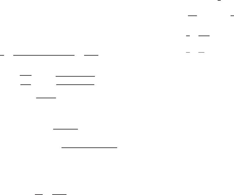
sion portion of the web, as shown in Fig. 4.59. References
4.60, 4.65, and 4.66 present the studies made by Nguyen
and Yu on the structural behavior of longitudinally rein-
forced beam webs.
In Europe, the design methods for profiled sheeting and
sections with stiffeners in the flanges and webs are provided
in Refs. 1.209 and 3.56.
The DSM provided in Appendix 1 of the North American
Specification can handle the available bending strength of
beams having longitudinal web stiffeners.
166 4 FLEXURAL MEMBERS
Figure 4.59 Typical sections for longitudinally reinforced beam specimens.
4.3.5 Combined Bending and Shear
When high bending and high shear act simultaneously, as
in cantilever beams and at interior supports of continuous
beams, the webs of beams may buckle at a lower stress than
if only one stress were present without the other. Such webs
must be safeguarded against buckling due to this combined
bending and shear.
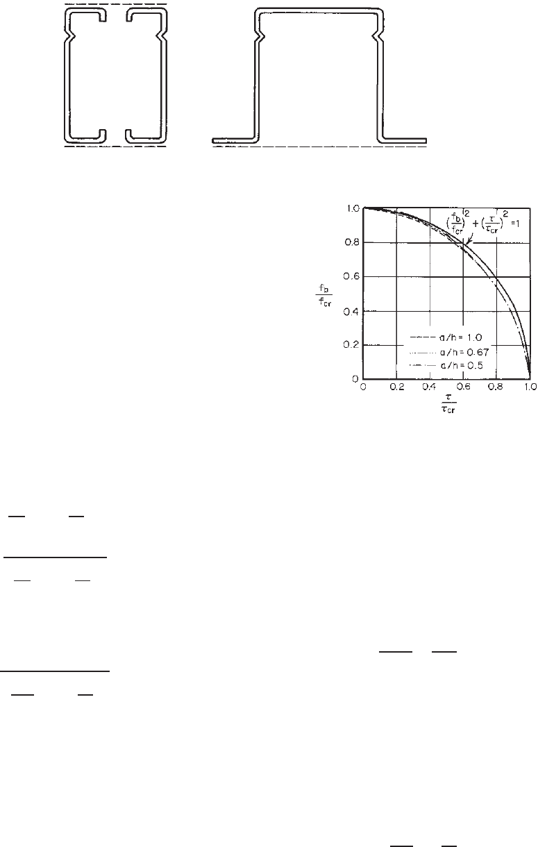
The critical combination of bending and shear stresses
in disjointed flat rectangular plates has been studied by
Timoshenko.
3.2
Figure 4.60 shows the interaction between
f
b
/f
cr
and τ/τ
cr
,inwhichf
b
is the actual computed
bending stress, f
cr
is the theoretical buckling stress in pure
bending, τ is the actual c omputed shear stress, and τ
cr
is
the theoretical buckling s tress in pure shear. It can be seen
from Fig. 4.60 that for a/h ratios ranging from 0.5 to 1.0 the
relationship between f
b
/f
cr
and τ/τ
cr
can be approximated
by Eq. (4.162a), which is a part of the unit c ircle:
f
b
f
cr
2
+
τ
τ
cr
2
= 1 (4.162a)
or
f
b
f
cr
2
+
τ
τ
cr
2
≤ 1 (4.162b)
By using proper safety factors, the following interaction
formula can be used for the allowable stress design of beam
webs subjected to the combined bending and shear stresses:
f
bw
F
bw
2
+
f
v
F
v
2
≤ 1 (4.163)
where f
bw
= actual compression stress at junction of
flange and web
F
bw
= allowable compressive stress
f
v
= actual average shear stress
F
v
= allowable shear stress,
For additional information on simply supported plates
under combined shear and uniformly distributed longitu-
dinal stresses, see Ref. 3.3.
Figure 4.60 Interaction relationship between f
b
/f
cr
and τ/τ
cr
.
4.63
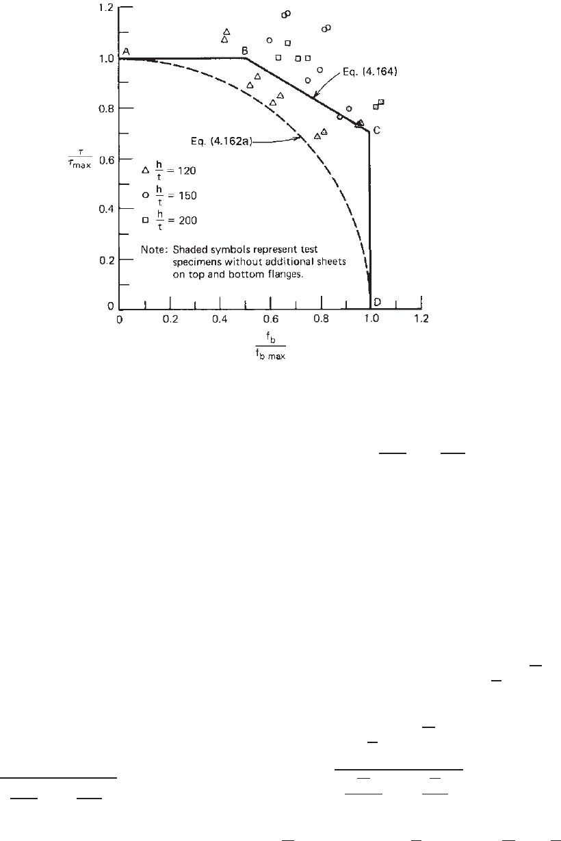
In the past, the structural strength of beam webs subjected
to a combination of bending and s hear has been studied by
LaBoube and Yu.
4.57,4.67
The results of 25 beam tests indi-
cated that Eq. (4.162a), originally developed for a disjointed
individual sheet, would be conservative for beam webs with
adequate transverse stiffeners, for which a diagonal tension
field action can be developed. Based on the test results
shown in Fig. 4.61, the following interaction equation was
developed for beam webs with transverse stiffeners satis-
fying the requirements of Section 4.3.2:
0.6
f
b
f
b,max
+
τ
τ
max
= 1.3 (4.164)
where f
b,max
= maximum computed stress governing
bending
τ
max
= maximum computed stress governing
shear for reinforced web
Accordingly, the allowable stress equation for webs rein-
forced with adequate transverse stiffeners can be expressed
as follows:
0.6
f
bw
F
bw
+
f
v
F
v
≤ 1.3 (4.165)
DESIGN OF BEAM WEBS 167
Figure 4.61 Interaction diagram for τ/τ
max
and f
b
/f
b, max.
Equation (4.165) is applicable only when f
bw
/F
bw
> 0.5
and f
v
/F
v
> 0.7.
For other conditions, the design of beam webs is
governed by either the allowable bending stress or the
allowable shear stress.
Instead of using stress ratios in Eqs. (4.163) and (4.165),
the 1986 and 1996 editions of the AISI Specification and
the North American Specification use strength ratios (i.e.,
moment ratio for bending and force ratio for shear) for
the interaction equations. The following design criteria
are adapted from Section C3.3 of the North American
Specification for combined bending and shear:
C3.3 Combined Bending and Shear
C3.3.1 ASD Method
For beams subjected to combined bending and shear, the
required flexural strength, M , and required shear strength, V ,
shall not exceed M
n
/
b
and V
n
/
v
, respectively.
For beams with unreinforced webs, the required flexural
strength, M , and required shear strength, V , shall also satisfy
the following interaction equation:
b
M
M
nxo
2
+
v
V
V
n
2
≤ 1.0 (4.166a)
For beams with transverse web stiffeners, when
b
M/M
nxo
> 0.5and
v
V/V
n
> 0.7, M and V shall
also satisfy the following interaction equation:
0.6
b
M
M
nxo
+
v
V
V
n
≤ 1.3 (4.166b)
where M
n
= nominal flexural strength when b ending alone is
considered
b
= safety factor for bending (see Section 4.2)
M
nxo
= nominal flexural strength about centroidal x axis
determined in accordance with Section 4.2.2
v
= safety factor for shear (see Section 4.3.3)
V
n
= nominal shear force when shear alone is
considered
C3.3.2 LRFD and LSD Methods
For beams subjected to combined bending and shear, the
required flexural strength [factored moment],
M,andthe
required shear strength [factored shear],
V , shall not exceed
φ
b
M and φ
v
V , respectively.
For beams with unreinforced webs, the required flexural
strength [factored moment],
M, and the required shear strength
[factored shear],
V , shall also satisfy the following equation:
)
*
*
+
M
φ
b
M
nxo
2
+
V
φ
v
V
n
2
≤ 1.0 (4.167a)
For beams with transverse web stiffeners, when
M/(φ
b
M
nxo
)>0.5andV/(φ
n
V
n
)>0.7, M and V shall
168 4 FLEXURAL MEMBERS
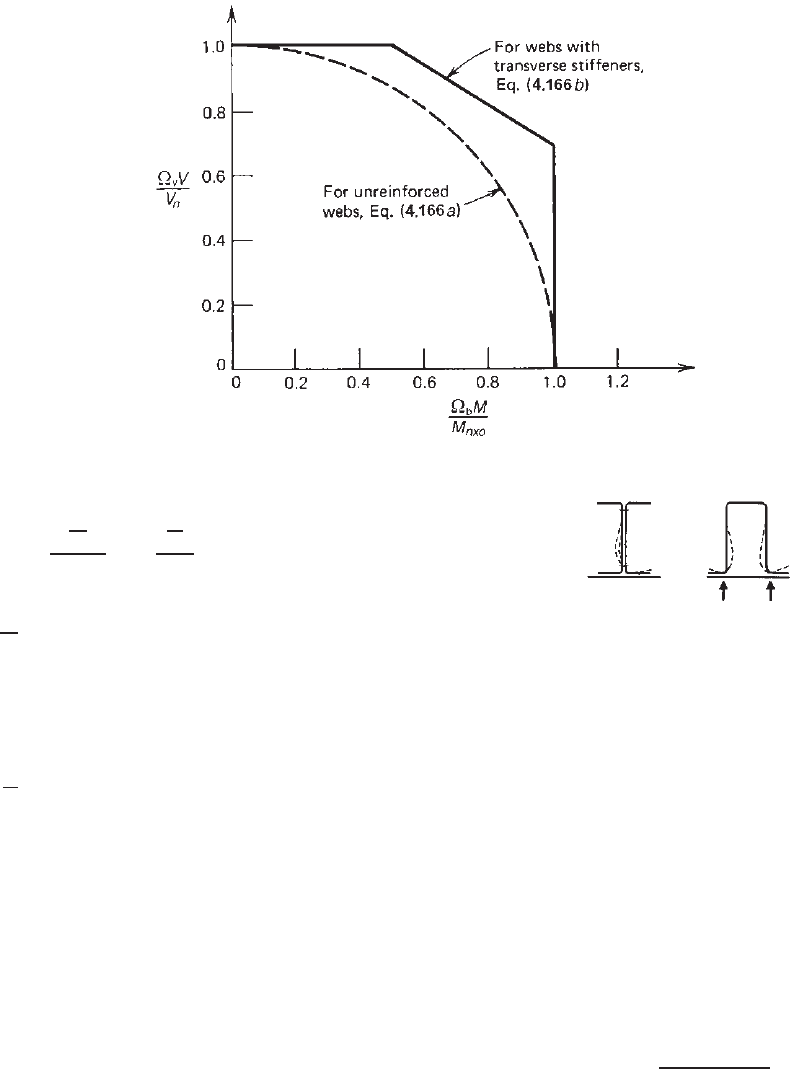
Figure 4.62 Interaction formulas for combined bending and shear using ASD method.
satisfy the following interaction equation:
0.6
M
φ
b
M
nxo
+
V
φ
v
V
n
≤ 1.3 (4.167b)
where M
n
= nominal flexural strength [moment resistance]
when bending alone is considered
M = required flexural strengrth [factored moment]
= M
u
(LRFD)
= M
f
(LSD)
φ
b
= resistance factor for bending (see Section 4.2)
M
nxo
= nominal flexural strength [moment resistance]
about the centroidal x axis determined in
accordance with Section 4.2.2
V = required shear strength [factored shear]
= V
u
(LRFD)
= V
f
(LSD)
φ
v
= resistance factor for shear (see Section 4.3.3)
V
n
= nominal shear strength [resistance] when shear
alone i s considered
Figure 4.62 shows t he interaction formulas using the ASD
method for the design of beam webs subjected to the combina-
tion of bending and shear. These design criteria are based on
Eqs. (4.166a) and (4.166b). A study conducted by Almoney
and Murray indicated that combined bending and shear is a
possible limit state for a continuous lapped Z-purlin system
and that the current design provisions accurately predict the
failure load.
4.173
4.3.6 Web Crippling
4.3.6.1 Web Cripping Strength of Beam Webs without
Holes When the end and load stiffeners are not used
in thin-walled cold-formed steel construction, the webs of
Figure 4.63 Web crippling of unfastened beams.
1.161
beams may cripple due to the high local intensity of the load
or reaction. Figure 4.63 shows the types of failure caused
by web crippling for I-beams and hat sections unfastened
to the support. The web crippling of I-beam webs is also
shown in Fig. 1.31.
The buckling problem of separate flat rectangular plates
under locally distributed edge forces has been studied
by numerous investigators, including Sommerfeld,
4.68
Timoshenko,
4.69
Leggett,
4.70
Hopkins,
4.71
Yama k i,
4.72
Zetlin,
4.73
White and Cottingham,
4.74
Khan and Walker,
4.75
Khan, Johns, and Hayman,
4.76
and others.
3.7
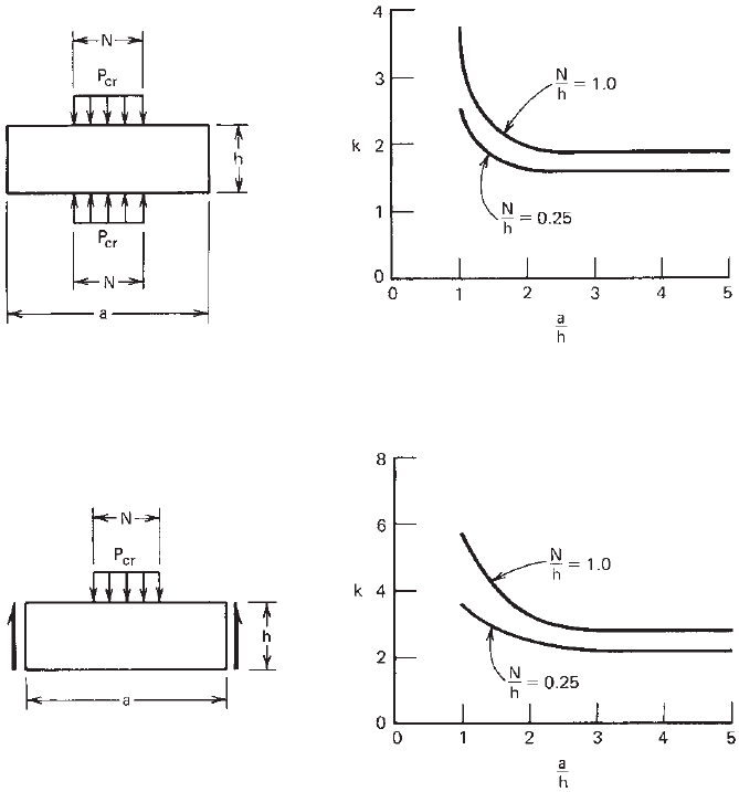
Based on
Refs. 4.75 and 4.76, the buckling load for the plates
subjected to locally distributed edge forces as shown in
Figs. 4.64 and 4.65 can be computed as
P
cr
=
kπ
2
Et
3
12
1 − μ
2
h
(4.168)
where k is the buckling coefficient depending on the ratios
of N /h and a/h as given in these two figures.
For steel beams having webs connected to flanges, theo-
retical and experimental investigations on web crippling
under partial edge loading have been conducted by Lyse
and Godfrey,
4.77
Rocky, Bagchi, and El-gaaly,
4.78–4.83,4.94
DESIGN OF BEAM WEBS 169
Figure 4.64 Buckling coefficient k for simply supported plates subjected to two opposite locally
distributed edge forces.
1.216,4.75
(Reproduced with permission from Walker, A. C. (Ed.), Design
and Analysis of Cold-Formed Sections, International Textbook Co., Glasgow and London, 1975.)
Figure 4.65 Buckl ing coefficient k for simply supported plates subjected to one locally distributed
edge force.
4.76
Roberts and Neware,
4.181
Bergfelt,
4.84
Edlund,
4.102
and
others. However, the theoretical analysis of web crippling
for cold-formed steel flexural members is rather compli-
cated because it involves the following factors:
1. Nonuniform stress distribution under the applied load
and adjacent portions of the web
2. Elastic and inelastic stability of the web element
3. Local yielding in the immediate region of load appli-
cation
4. Bending produced by eccentric load (or reaction)
when it is applied on the bearing flange at a distance
beyond the curved transition of the web
5. Initial out-of-plane imperfection of plate elements
6. Edge restraints provided by beam flanges based on
the fastened condition to the support and interaction
between flange and web elements
7. Inclined webs for decks and panels
For these reasons, in the United States, the AISI
1946–1968 design provisions for web crippling were based
on the extensive experimental investigations conducted
at Cornell University by Winter and Pian
4.85
and by
Zetlin
4.73
in the 1940s and 1950s. The AISI design
previsions were revised in 1980, 1986, and 1996 based on
the additional research work conducted at the University
of Missouri-Rolla by Hetrakul and Yu,
4.58,4.94
Yu,
4.86
Bhakta, LaBoube, and Yu,
4.174
and Cain, LaBoube, and
Yu.
4.175
These modified provisions have been used for
high-strength steels, high h/t ratios, and the increase
of end-one-flange web crippling strength for Z-sections
fastened to the support member. In these experimental
investigations, the web crippling tests have been carried
out under the following four loading conditions for beams
having single unreinforced webs and I-beams:
1. End one-flange (EOF) loading
2. Interior one-flange (IOF) loading
170 4 FLEXURAL MEMBERS
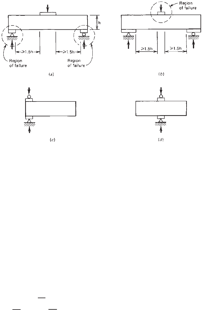
Figure 4.66 Loading conditions for web crippling tests: (a) EOF loading; (b) IOF loading;
(c) ETF loading; (d ) ITF loading.
3. End two-flange (ETF) loading
4. Interior two-flange (ITF) loading
All loading conditions are illustrated in Fig. 4.66. In
Figs. 4.66a and 4.66b the distances between bearing plates
were kept to no less than 1.5 times the web depth in order
to avoid the two-flange action.
The developments of the 1996 and earlier AISI design
requirements for web crippling and the research background
information were summarized by Yu in the third edition of
the book.
1.354
In Canada, the study of web crippling of cold-formed
steel members was initiated at the University of Waterloo
by Wing and Schuster in 1981.
4.88,4.89,4.98
In the 1990s,
Prabakaran and Schuster developed the following unified
web crippling equation for the CSA standard S136-94 with
variable coefficients
1.177,4.177,4.238
:
P
n
= Ct
2
F
y
(sin θ)(1 − C
R
√
R
∗
)
× (1 + C
N
√
N
∗
)(1 − C
H
√
H
∗
) (4.169)
in which C is the web crippling coefficient, C
H
is the web
slenderness coefficient, C
N
is the bearing length coefficient,
C
R
is inside bend radius coefficient, H * = h/t, N * = n/t,
and R* = r/t. All coefficients were listed in three separate
tables for built-up sections (I-beams), shapes having single
webs, and deck sections (multiple webs). Subsequently,
Beshara and Schuster developed additional web crippling
coefficients based on the above-mentioned research data
and the later investigations conducted at (a) the University
of Missouri-Rolla by Santaputra,
4.233
Santaputra, Parks, and
Yu,
4.97,4.104
Langan, LaBoube, and Yu,
3.185,3.198
and Wu,
Yu, and Laboube
4.183,4.192
; (b) the University of Waterloo
by Gerges,
4.239
Gerges and Schuster,
4.178
Beshara,
4.240
and
Beshara and Schuster
4.241–4.243
; and (c) the University of
Sydney by Young and Hancock.
4.182
In 2001, the North American specification adopted the
unified web crippling equation in Section C3.4.1 for deter-
mining the nominal web crippling strengths of the following
five different section types:
1. Built-up sections
2. Single-web channel and C-sections
3. Single-web Z-sections
4. Single hat sections
5. Multiweb deck sections
The limitations of h/t, N /t, N /h, R/t,andθ for using
these tabulated coefficients are given in all five tables. Also
included in these tables are safety factors for ASD and
resistance factors for LRFD and LSD.
The 2001 design provisions were retained in the 2007
edition of the North American Specification, in which an
alternative method was added for end-one-flange loading
condition on a C- or Z-section with an overhang on
one side of the bearing plate. This method was based
on the research findings of Holesapple and Laboube.
4.235
Based on extensive testing, more web crippling coefficients
DESIGN OF BEAM WEBS 171
were developed by Wallace for both the unfastened and
fastened cases of end-one-flange loading for multiweb deck
sections.
4.246
The current design provisions for web crip-
pling strengths of webs without holes are included in
Section C3.4.1 of the North American specification.
4.3.6.2 Web Cripping Strength of C-Section Webs with
Holes Since 1990, the structural behavior of perforated
web elements of flexural members subjected to web crip-
pling and a combination of web crippling and bending
has been investigated at the University on Missouri-Rolla
by Langan et al.,
3.185,3.198
Uphoff,
3.199
Deshmukh,
3.200
and
Laboube, Yu, Deshmukh, and Uphoff.
3.193
It was found
that the reduction in web crippling strength is affected
primarily by the size of the hole as reflected in the d
h
/h
ratio and the location of the hole x /h ratio. New reduction
equations for the web crippling strength of C-section webs
with holes were developed for inclusion in Supplement No.
1 to the 1996 edition of the AISI Specification.
1.333–1.335
The
same design equations were retained in Section C3.4.2 of
the North American Specification. It shoulb be noted that
the design equations for determining the reduction factor
can only be applicable for the C-sections with web holes
subjected to the limitations listed in Section C3.4.2 of the
Specification.
4.3.6.3 North American Design Criteria for Web
Cripping The following excerpts are adapted from
Section C3.4 of the 2007 edition of the North Amer-
ican Specification, which provide the design equations
for computing the available web crippling strengths of
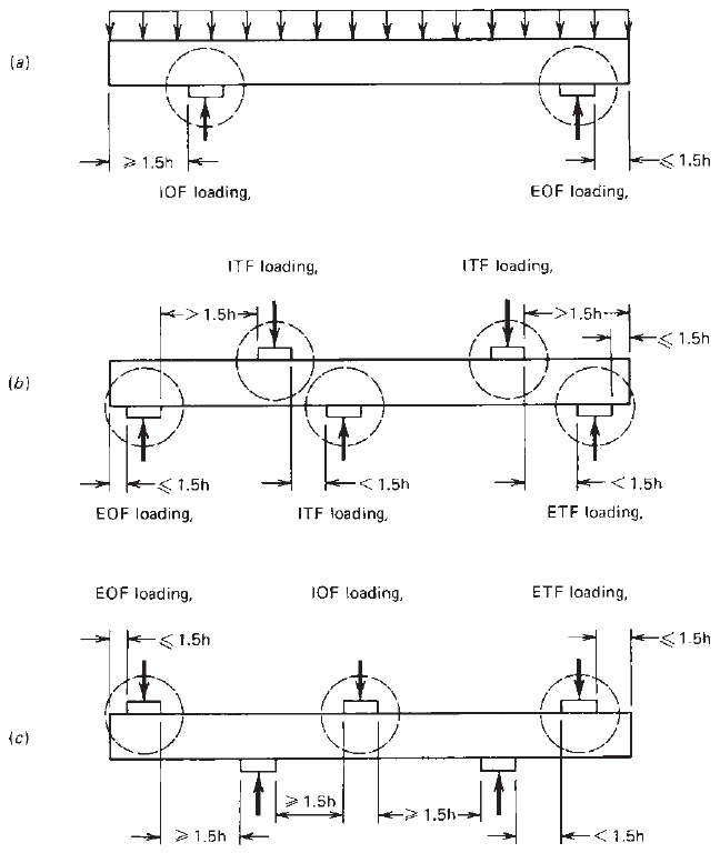
cold-formed steel members. The loading cases (EOF, IOF,
ETF, and ITF) are shown in Fig. 4.67. Examples 4.21–4.23
illustrate the applications of design equations.
Figure 4.67 Application of AISI loading cases.
172 4 FLEXURAL MEMBERS
C3.4.1 Web Crippling Strength [Resistance] of Webs
without Holes
The nominal web crippling strength [resistance], P
n
, shall be
determined in accordance with Eq. (4.170) or Eq. (4.171), as
applicable. The safety factors and resistance factors in Tables
4.8–4.12 shall be u sed to determine the allowable strength or
design strength [factored resistance] in accordance with the
applicable design method in Section 3.3.1, 3.3.2, or 3.3.3:
P
n
= Ct
2
F
y
sin θ
1 − C
R
R
t
1 + C
N
N
t
1 − C
h
h
t
(4.170)
where P
n
=nominal web crippling strength [resistance]
C = coefficient from Table 4.8, 4.9, 4.10, 4.11, or 4.12
t = web thickness
F
y
= design yield stress as determined in accordance
with Section 2.2
θ = angle between plane of web and plane of bearing
surface, 45
◦
≤ θ ≤ 90
◦
C
R
= inside bend radius coefficient from Table 4.8, 4.9,
4.10, 4.11, or 4.12
R = inside bend radius
C
N
= bearing length coefficient from Table 4.8, 4.9,
4.10, 4.11, or 4.12
N = bearing lengt h [
3
4
in. (19 mm) minimum]
C
h
= web slenderness coefficient from Table 4.8, 4.9,
4.10, 4.11, or 4.12
h = flat dimension of web measured in plane of web
Alternatively, for an end-one-flange loading condition on
a C- or Z-section, the nominal web crippling strength [resis-
tance], P
nc
, with an overhang on one side, shall be permitted
to be calculated as follows, except that P
nc
shall not be larger
than the interior-one-flange loading condition:
P
nc
= αP
n
(4.171)
where P
nc
is the nominal web crippling strength [resistance]
of C- and Z-sections with overhang(s) and
α =
1.34
(
L
o
/h
)
0.26
0.009(h/t) + 0.3
≥ 1.0 (4.172)
where L
o
= overhang length measured from edge of bearing
to end of member
P
n
= nominal web crippling strength [resistance] with
end-one-flange loading as calculated by Eq.
(4.170) and Tables 4.9 and 4.10
Equation (4.171) shall be limited to 0.5 ≤L
o
/h ≤ 1.5 and
h/t ≤ 154. For L
o
/h or h/t outside these limits, α = 1.
Webs of members in bending for which h/t is greater than
200 shall be provided with means of transmitting concentrated
loads or reactions directly into the web(s).
The terms P
n
and P
nc
shall represent the nominal strengths
[resistances] for load or reaction for one solid web connecting
top and bottom flanges. For webs consisting of two or more
such sheets, P
n
and P
nc
shall be calculated for each individual
sheet and the results added to obtain the nominal strength for
the full section.
One-flange loading or reaction shall be defined as the
condition where the clear distance between the bearing edges
of adjacent opposite concentrated loads or reactions is equal
to or greater than 1.5h.
Two-flange loading or r eaction shall be defined as the
condition where the clear distance between the bearing edges
Table 4.8 Safety Factors, Resistance Factors, and Coefficients for Built-Up Sections
U.S. and Mexico
ASD LRFD Canada
Support and Flange Conditions Load Cases CC
R
C
N
C
h
w
φ
w
LSD φ
w
Limits
Fastened to
support
Stiffened or
partially
stiffened
flanges
One-flange
loading or
reaction
End 10 0.14 0.28 0.001 2.00 0.75 0.60 R/t ≤ 5
Interior 20.5 0.17 0.11 0.001 1.75 0.85 0.75 R/t ≤ 5
Unfastened Stiffened or
partially
stiffened
flanges
One-flange
loading or
reaction
End 10 0.14 0.28 0.001 2.00 0.75 0.60 R/t ≤ 5
Interior 20.5 0.17 0.11 0.001 1.75 0.85 0.75 R/t ≤ 3
Two-flange
loading or
reaction
End 15.5 0.09 0.08 0.04 2.00 0.75 0.65 R/t ≤ 3
Interior 36 0.14 0.08 0.04 2.00 0.75 0.65 R/t ≤ 3
Unstiffened
flanges
One-flange
loading or
reaction
End 10 0.14 0.28 0.001 2.00 0.75 0.60 R/t ≤ 5
Interior 20.5 0.17 0.11 0.001 1.75 0.85 0.75 R/t ≤ 3
DESIGN OF BEAM WEBS 173
Table 4.9 Safety Factors, Resistance Factors, and Coefficients for Single-Web Channel and C-Sections
U.S. and Mexico
ASD LRFD Canada
Support and Flange Conditions Load Cases CC
R
C
N
C
h
w
φ
w
LSD φ
w
Limits
Fastened to
support
Stiffened or
partially
stiffened
flanges
One-flange
loading or
reaction
End 4 0.14 0.35 0.02 1.75 0.85 0.75 R/t ≤ 9
Interior 13 0.23 0.14 0.01 1.65 0.90 0.80 R/t ≤ 5
Two-flange
loading or
reaction
End 7.5 0.08 0.12 0.048 1.75 0.85 0.75 R/t ≤ 12
Interior 20 0.10 0.08 0.031 1.75 0.85 0.75 R/t ≤ 12
Unfastened Stiffened or
partially
stiffened
flanges
One-flange
loading or
reaction
End 4 0.14 0.35 0.02 1.85 0.80 0.70 R/t ≤ 5
Interior 13 0.23 0.14 0.01 1.65 0.90 0.80 R/t ≤ 5
Two-flange
loading or
reaction
End 13 0.32 0.05 0.04 1.65 0.90 0.80 R/t ≤ 3
Interior 24 0.52 0.15 0.001 1.90 0.80 0.65 R/t ≤ 3
Unstiffened
flanges
One-flange
loading or
reaction
End 4 0.40 0.60 0.03 1.80 0.85 0.70 R/t ≤ 2
Interior 13 0.32 0.10 0.01 1.80 0.85 0.70 R/t ≤ 1
Two-flange
loading or
reaction
End 2 0.11 0.37 0.01 2.00 0.75 0.65 R/t ≤ 1
Interior 13 0.47 0.25 0.04 1.90 0.80 0.65 R/t ≤ 1
of adjacent opposite concentrated loads or reactions is less than
1.5h.
End loading or reaction shall be defined as the condition
where t he distance from the edge of the bearing t o the end of
the member is equal to or less than 1.5h.
Interior loading or reaction shall be defined as the condition
where the distance from the edge of the bearing to the end
of the member is greater than 1.5h, except as otherwise noted
herein.
Table 4.8 shall apply to I-beams made from two channels
connected back to back where h/t ≤ 200, N /t ≤ 210, N /h
≤ 1.0, and θ = 90
◦
. See Section C3.4.1 of Commentary for
further explanation.
Table 4.9 shall apply to single-web channel and C-section
members where h/t ≤ 200, N /t ≤ 210, N /h ≤ 2.0, and θ =
90
◦
. In Table 4.9, for interior two-flange loading or reaction of
members having flanges fastened to the support, the distance
from the edge of the bearing to the end of the member shall
be extended at least 2.5h. For unfastened cases, the distance
from the edge of the bearing to the end of the member shall
be extended at least 1.5h.
Table 4 .10 shall apply to single-web Z-section members
where h/t ≤ 200, N /t ≤ 210, N /h ≤ 2.0, and θ = 90
◦
.
In Table 4.10, for interior two-flange loading or reaction of
members having flanges fastened to the support, the distance
from the edge of the bearing to the end of the member shall
be extended at least 2.5h; for unfastened cases, the distance
from the edge of the bearing to the end of the member shall
be extended at least 1.5h.
Table 4.11 shall apply to single hat section members where
h/t ≤ 200, N /t ≤ 200, N /h ≤ 2, and θ = 90
◦
.
Table 4.12 shall apply to multiweb section members where
h/t ≤ 200, N /t ≤ 210, N /h ≤ 3, and 45
◦
≤ θ ≤ 90
◦
.
C3.4.2 Web Crippling Strength of C-Section Webs with
Holes
Where a web hole i s within the bearing length, a bearing
stiffener shall be used.
For beam webs with holes, the web crippling strength
[factored resistance] shall be computed in accordance with
Section C3.4.1 multiplied by the reduction factor, R
c
,given
in Section C3.4.2 of the specification.
The provisions of this section shall apply within the
following limits:
1. d
h
/h ≤ 0.7,
2. h/t ≤ 200,
3. holes centered at middepth of the web,
4. clear distance between holes ≥ 18 in. (457 mm),
5. distance between the end of the member and the edge of
the hole ≥ d,
6. noncircular holes, corner radii ≥ 2 t,

174 4 FLEXURAL MEMBERS
Table 4.10 Safety Factors, Resistance Factors, and Coefficients for Single-Web Z-Sections
U.S. and Mexico
ASD LRFD Canada
Support and Flange Conditions Load Cases CC
R
C
N
C
h
w
φ
w
LSD φ
w
Limits
Fastened to
support
Stiffened or
partially
stiffened
flanges
One-flange
loading or
reaction
End 4 0.14 0.35 0.02 1.75 0.85 0.75 R/t ≤ 9
Interior 13 0.23 0.14 0.01 1.65 0.90 0.80 R/t ≤ 5.5
Two-flange
loading or
reaction
End 9 0.05 0.16 0.052 1.75 0.85 0.75 R/t ≤ 12
Interior 24 0.07 0.07 0.04 1.85 0.80 0.70 R/t ≤ 12
Unfastened Stiffened or
partially
stiffened
flanges
One-flange
loading or
reaction
End 5 0.09 0.02 0.001 1.80 0.85 0.75 R/t ≤ 5
Interior 13 0.23 0.14 0.01 1.65 0.90 0.80 R/t ≤ 5
Two-flange
loading or
reaction
End 13 0.32 0.05 0.04 1.65 0.90 0.80 R/t ≤ 3
Interior 24 0.52 0.15 0.001 1.90 0.80 0.65 R/t ≤ 3
Unstiffened
flanges
One-flange
loading or
reaction
End 4 0.40 0.60 0.03 1.80 0.85 0.70 R/t ≤ 2
Interior 13 0.32 0.10 0.01 1.80 0.85 0.70 R/t ≤ 1
Two-flange
loading or
reaction
End 2 0.11 0.37 0.01 2.00 0.75 0.65 R/t ≤ 1
Interior 13 0.47 0.25 0.04 1.90 0.80 0.65 R/t ≤ 1
Table 4.11 Safety Factors, Resistance Factors, and Coefficients for Single Hat Sections
U.S. and Mexico
Support ASD LRFD Canada
Conditions Load Cases CC
R
C
N
C
h
w
φ
w
LSD φ
w
Limits
Fastened to
support
One-flange loading
or reaction
End 4 0.25 0.68 0.04 2.00 0.75 0.65 R/t ≤ 5
Interior 17 0.13 0.13 0.04 1.80 0.85 0.70 R/t ≤ 10
Two-flange loading
or reaction
End 9 0.10 0.07 0.03 1.75 0.85 0.75 R/t ≤ 10
Interior 10 0.14 0.22 0.02 1.80 0.85 0.75 R/t ≤ 10
Unfastened One-flange loading
or reaction
End 4 0.25 0.68 0.04 2.00 0.75 0.65 R/t ≤ 4
Interior 17 0.13 0.13 0.04 1.80 0.85 0.70 R/t ≤ 4
7. noncircular holes, d
h
≤ 2.5in.(64 mm) and L
h
≤ 4.5in.
(114 mm),
8. circular holes, diameters ≤ 6 in. (152 mm), and
9. d
h
> 9/16 in.(14 mm)
where d
h
= depth of web hole
h = depth of flat portion of web measured along plane
of web
t = web thickness
d = depth of cross section
L
h
= length of web hole
For end-one-flange reaction [Eq. (4.170) with Table 4.9]
where a web hole is not within the bearing length, the reduction
factor, R
c
, shall be calculated as follows:
R
c
= 1.01 −
0.325d
h
h
+
0.083x
h
≤ 1.0 (4.173)
N ≥ 1in. (25 mm)
For interior-one-flange reaction [Eq. (4.170) with Table 4.9]
where any portion of a web hole is not within the bearing
length, the reduction factor, R
c
, shall be calculated as follows: