Yu W., LaBoube R.A. Cold-Formed Steel Design
Подождите немного. Документ загружается.


DESIGN OF BEAM WEBS 175
Table 4.12 Safety Factors, Resistance Factors, and Coefficients for Multiweb Deck Sections
U.S. and Mexico
Support ASD LRFD Canada
Conditions Load Cases CC
R
C
N
C
h
w
φ
w
LSD φ
w
Limits
Fastened to
support
One-flange loading
or reaction
End 4 0.04 0.25 0.025 1.70 0.90 0.80 R/t ≤ 20
Interior 8 0.10 0.17 0.004 1.75 0.85 0.75 R/t ≤ 10
Two-flange loading
or reaction
End 9 0.12 0.14 0.040 1.80 0.85 0.70 R/t ≤ 10
Interior 10 0.11 0.21 0.020 1.75 0.85 0.75 R/t ≤ 10
Unfastened One-flange loading
or reaction
End 3 0.04 0.29 0.028 2.45 0.60 0.50 R/t ≤ 20
Interior 8 0.10 0.17 0.004 1.75 0.85 0.75 R/t ≤ 20
Two-flange loading
or reaction
End 6 0.16 0.15 0.050 1.65 0.90 0.80 R/t ≤ 5
Interior 17 0.10 0.10 0.046 1.65 0.90 0.80 R/t ≤ 5
R
c
= 0.90 −
0.047d
h
h
+
0.053x
h
≤ 1.0 (4.174)
N ≥ 3in. (76 mm)
where x = nearest distance between web hole and edge of
bearing
N = bearing length
In addition to the research work mentioned in Sections
4.3.6.1 and 4.3.6.2, the web crippling strengths of cold-formed
steel beams have been studied by numerious researchers during
the past decade. For more information on web crippling, the
reader is referred to Refs. 4.105–4.107, 4.179–4.181, 4.184,
and 4.248–4.273.
4.3.7 Combined Web Crippling and Bending
In Section 4.3.6, the web crippling limit state of cold-
formed steel beams was discussed. The design formulas
were used to prevent any localized failure of webs resulting
from the bearing pressure due to reactions or concen-
trated loads without consideration of the effect of other
stresses.
In practical applications, a high bending moment may
occur at the location of the applied concentrated load in
simple span beams. For continuous beams, the reactions
at interior supports may be combined with high bending
moments and/or high shear. Under these conditions, the web
crippling strength as determined in Section 4.3.6 may be
reduced significantly due to the effect of bending moment.
The interaction relationship for the combination of bearing
pressure and bending stress has been studied by numerous
researchers.
4.58,4.80,4.81,4.86–4.88,4.90–4.92,4.237,4.244,4.245,4.249,4.252,
4.265,4.266,4.271
Based on the results of beam tests with
combined web crippling and bending, interaction formulas
have been developed for use in several design specifica-
tions.
4.3.7.1 Shapes Having Single and Multiple Unrein-
forced Webs For the AISI Specification, the interaction
of combined bending and web crippling has been recog-
nized since 1980. The interation equation used in the 1980,
1986, and 1996 editions of the Specification was devel-
oped by Hetrarul and Yu in 1978 on the basis of the test
results for combined web crippling and bending achieved at
Cornell University,
4.85
the University of Missouri-Rolla,
4.58
and United States Steel Research Laboratory.
4.92
See Figs.
4.68, 4.69, and 4.70. The research findings and the devel-
opment of design e quations were summarized by Yu in the
third edition of the book.
1.354
Due to the adoption of the unified web crippling equation
by the N orth American Specification in 2001, the interac-
tion equations for the combination of bending and web
crippling were reevaluated by LaBoube, Schuster, and
Wallace in 2002 using Section 4.3.6.3 for determining
the web crippling strength.
4.244,4.245
The experimental data
were based on research studies conducted by Winter and
Pian,
4.85
Hetrarul and Yu,
4.58,4.94
Yu,
1.354,4.86
and Young and
Hancock.
4.249
The safety factors for ASD and the resistance
factors for LRFD and LSD were selected from the calibra-
tion of test data using the procedures given in Chapter F of
the North American Specification.
Consequently, the following design equations were
developed for the combined bending and web crippling of
cold-formed steel beams in the Specification.
A. ASD Method
(a) For shapes having single unreinforced webs,
0.91
P
P
n
+
M
M
nxo
≤
1.33
(4.175)
(b) For shapes having multiple unreinforced webs such
as I-sections or similar sections that provide a high
176 4 FLEXURAL MEMBERS
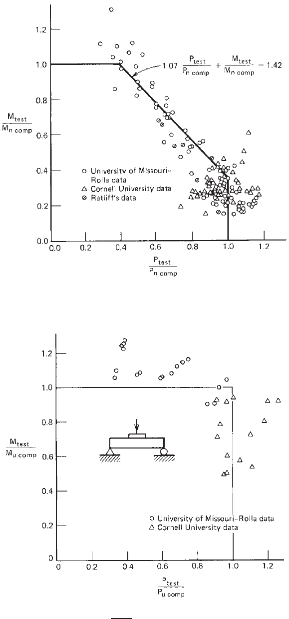
Figure 4.68 Graphic presentation for web crippling (IOF loading) and combined web crippling
and bending for specimens having single unreinforced webs.
4.58
Figure 4.69 Interaction between web crippling and bending for I-beam specimens having
unreinforced webs [when h/t ≤ 2.33/
E
y
/E and ρ = 1].
4.58
DESIGN OF BEAM WEBS 177
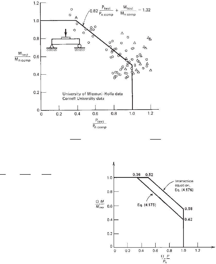
Figure 4.70 Interaction between web crippling and bending for I-beam specimens having
unreinforced webs [when h/ t ≤ 2.33
F
y
/E combined with ρ<1, and 2.33/
F
y
/E < h/t ≤
200 combi ned with any value of w/t] (IOF loading).
4.58
degree of restraint against rotation of the web,
0.88
P
P
n
+
M
M
nxo
≤
1.46
(4.176)
where P = required strength for concentrated load
or reaction in the presence of bending
moment
P
n
= nominal strength for concentrated or
reaction in absence of bending moment
determined in accordance with Section
4.3.6
M = required flexural strength at, or
immediately adjacent to, the point of
application of the concentrated load or
reaction, P
M
nxo
= nominal flexural strength about the x
axis determined in accordance with
Section 4.2.2
= safety factor for combined bending and
web crippling
= 1.70
Equations (4.175) and (4.176) are shown graphi-
cally in Fig. 4.71.
Since the safety factor for bending (Section 4.2.2),
b
, and the safety factor for web crippling (Section
Figure 4.71 ASD interaction equations for combined web crip-
pling and bending (shapes having single and multiple unreinforced
webs).
4.3.6),
w
, are not the same as the safety factor for
combined bending and web crippling, the design should
also satisfy M ≤ M
nxo
/
b
and P ≤ P
n
/
w
.
178 4 FLEXURAL MEMBERS
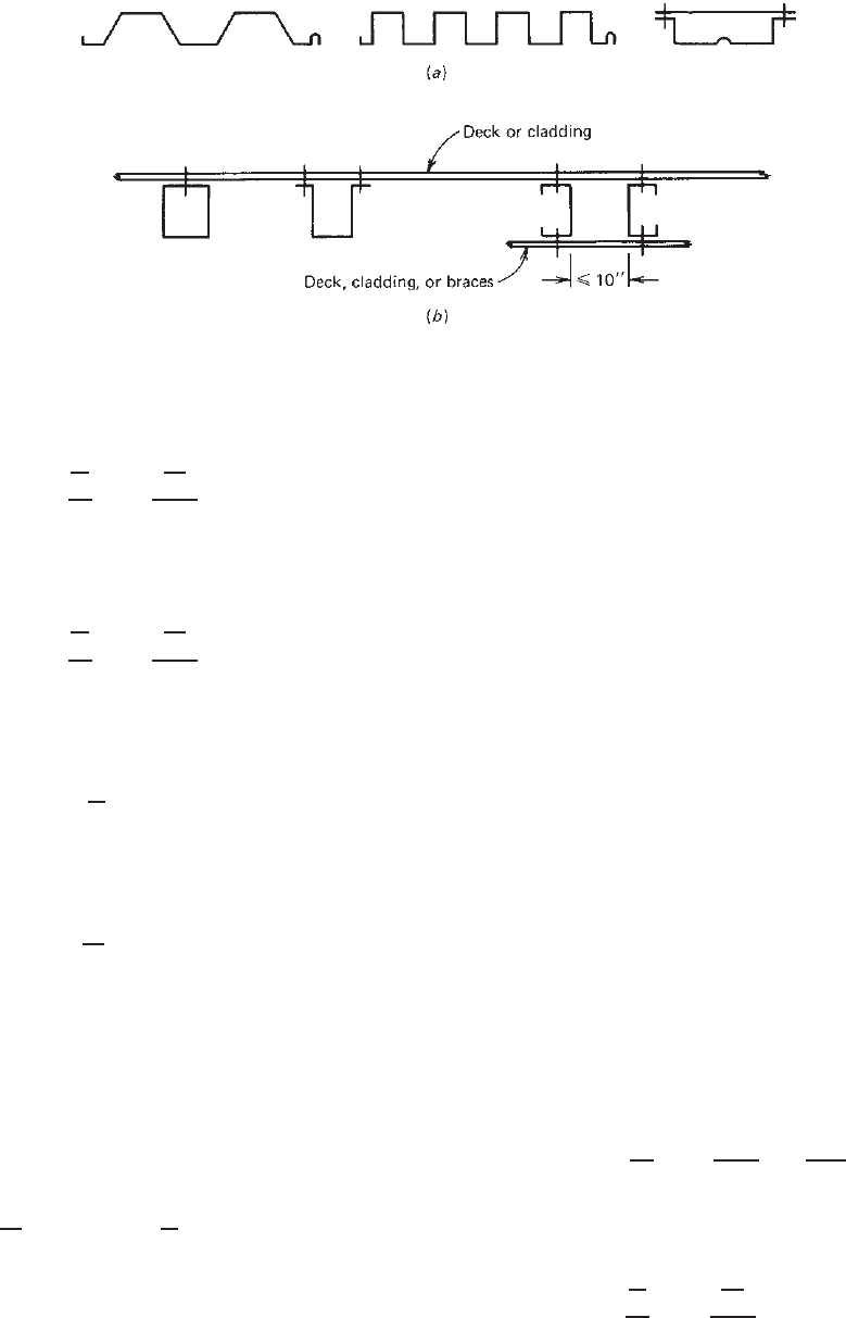
Figure 4.72 Sections used for exception clauses
1.346
:(a) decks; (b) beams.
B. LRFD and LSD Methods
(a) For shapes having single unreinforced webs,
0.91
P
P
n
+
M
M
nxo
≤ 1.33φ (4.177)
(b) For shapes having multiple unreinforced webs such
as I-sections or similar sections that provide a high
degree of restraint against rotation of the web,
0.88
P
P
n
+
M
M
nxo
≤ 1.46φ (4.178)
where the required strength for concentrated load or
reaction (factored concentrated load or reaction) in
the presence of a bending moment is given as
P =
P
u
(LRFD)
P
f
(LSD)
the required flexural strength (factored moment) at
or immediately adjacent to the point of application
of the concentrated load or reaction as
M =
M
u
(LRFD)
M
f
(LSD)
and the resistance factor for combined bending and
web crippling as
φ =
0.90 (LRFD)
0.75 (LSD)
Since the resistance factor for bending (Section 4.2.2),
φ
b
, and the resistance factor for web crippling (Section
4.3.6), φ
w
, are not the same as the resistance factor for
combined bending and web crippling, the design should
also satisfy
M ≤ φ
b
M
nxo
and P ≤ φ
w
P
n
.
Example 4.21 below illustrates the applications of the
design equations.
In the North American Specification, an exception clause
is included for the interior supports of continuous spans
using the decks and beams as shown in Fig. 4.72. This
is because the results of continuous beam tests of steel
decks
4.86
and several independent studies of individual
manufacturers indicate that for these types of members the
postbuckling behavior of beam webs at interior supports
differs from the type of failure mode occurring under
concentrated loads on single-span beams. This postbuckling
strength enables the member to redistribute the moments
in continuous beams. For this reason, Eqs. (4.175) and
(4.177) may be found to be conservative for determining
the load-carrying capacity of continuous spans on the basis
of the conventional elastic design. If localized distortions
of webs over interior supports as shown in Fig. 4.73 are
permitted, the inelastic flexural reserve capacity due to
partial plastification of beam cross section and moment
redistribution may be used, as discussed in Section 4.3.8.
4.3.7.2 Nested Z-Shapes In the 1996 edition of the AISI
Specification, design provisions were added for nested Z-
shapes. The same design equations are retained in the North
American Specification. When two nested Z-shapes are
subject to a combination of bending and concentrated load
or reaction, these members shall be designed to meet the
following requirements of Section C3.5.1 and C3.5.2 of the
2007 edition of the North American Specification.
A. ASD Method
0.86
P
P
n
+
M
M
nxo
≤
1.65
(4.179)
where M
nxo
is the nominal flexural strength for two
nested Z-sections and = 1.70.
B. LRFD and LSD Methods
0.86
P
P
n
+
M
M
nxo
≤ 1.65φ (4.180)
DESIGN OF BEAM WEBS 179
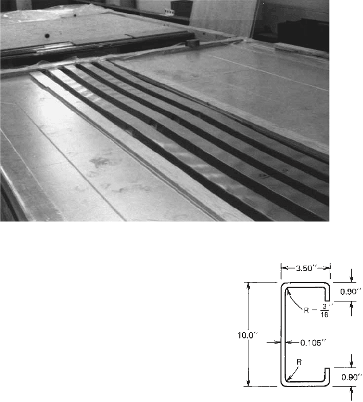
Figure 4.73 Two-span continuous beam tests using uniform loading.
in which φ equals 0.90 (LRFD) and 0.80 (LSD). Other
symbols were defined previously.
The above two equations were originally derived by
Laboube, N unnery, and Hodges from the experimental work
summarized in Ref. 4.176 and reevaluated in 2003 using
revised web crippling equations. These equations are valid
only for the shapes that meet the following limits: h/t ≤
150, N /t ≤ 140, F
y
≤ 70 ksi (483 MPa, or 4920 kg/cm
2
),
and R/t ≤ 5.5. In addition, the following conditions shall
also be satisfied: (1) the ends of each section shall be
connected to another section by a minimum of two
1
/
2
-in.-
(12.7-mm-) diameter A307 bolts through the web, (2) the
combined section is connected to the support by a minimum
of two
1
/
2
-in.- (12.7-mm-) diameter A307 bolts through the
flanges, (3) the webs of the two sections are in contact,
and (4) the ratio of the thicker to thinner part does not
exceed 1.3.
Example 4.21 For the channel section shown in Fig. 4.74
to be used as a simply supported beam:
1. Determine the allowable end reaction P
max
to prevent
web crippling by considering it as a one-flange
loading condition with N = 3.5 in.
2. Determine the allowable interior load to prevent web
crippling by considering the load as a one-flange
loading condition with N = 5 in. and assuming that
the applied bending moment M at the location of
the interior load is less than 42% of the allowable
Figure 4.74 Example 4 .21.
bending moment M
nxo
/ permitted if bending stress
only exists.
3. Same as item 2, except that the applied bending
moment M at the location of the interior load is equal
to the allowable bending moment M
nxo
/.
Use F
y
= 50 ksi and the A SD method. Assume that
the bottom flange of the beam is fastened to the
support.
SOLUTION
1. Allowable End Reaction for Web Crippling (One-
Flange Loading). Based on Eq. (4.170), the nominal

180 4 FLEXURAL MEMBERS
web crippling strength can be computed as follows:
P
n
= Ct
2
F
y
sin θ
1 − C
R
R
t
1 + C
N
N
t
×
1 − C
h
h
t
where h/t = [10 – 2(0.105 + 0.1875)]/0.105 =
89.67 < 200
N /t = 3.5/0.105 = 33.33 < 210
N /h = 3.5/[10 – 2(0.105 + 0.1875)] = 0.37
< 2.0
R/t = 0.1875/0.105 = 1.786 < 9
θ = 90
◦
From Table 4.9 for a simple web channel, C = 4,
C
R
= 0.14, C
N
= 0.35, C
h
= 0.02, and
w
= 1.75.
Therefore,
P
n
= 4(0.105)
2
(50)(sin 90
◦
)[1 − 0.14
√
1.786]
× [1 + 0.35
√
33.33][1 − 0.02
√
89.67]
= 4.39 kips
The allowable end reaction is then
P
a
=
P
n
w
=
4.39
1.75
= 2.51 kips
2. Allowable Interior Load for Web Crippling
(M<0.42M
nxo
/). According to Eq. (4.170),
the nominal web crippling strength for interior
load without considering the effect of the bending
moment is
P
n
= Ct
2
F
y
sin θ
1 − C
R
R
t
1 + C
N
N
t
×
1 − C
h
h
t
From Table 4.9 for interior one-flange loading, C
= 13, C
R
= 0.23, C
N
= 0.14, C
h
= 0.01, and
w
=
1.65. Therefore,
P
n
= 13(0.105)
2
(50)(sin 90
◦
)[1 − 0.23
√
1.786]
× [1 + 0.14
√
33.33][1 − 0.01
√
89.67]
= 8.13 kips
The allowable interior load for web crippling is P
a
=
P
n
/
w
= 8.13/1.65 = 4.93 kips. Because the applied
moment M at the location of the interior load is less
than 42% of the allowable bending moment M
nxo
/
permitted if bending stress only exists, Eq. (4.175)
is not applicable. See Fig. 4.71. For this case, the
computed allowable interior load of 4.93 kips should
be used without any reduction due to combined web
crippling and bending.
3. Allowable Interior Load for Web Crippling (M =
M
nxo
/ = M
nxo
/1.70). From item 2, the computed
nominal interior load for web crippling is 8.13 kips.
Because M = M
nxo
/1.70, which is less than M =
M
nxo
/1.67 for bending, the beam is to be designed for
the allowable bending moment for combined bending
and web crippling. The applied concentrated load
should be reduced according to Eq. (4.175), as shown
in Fig. 4.71, in order to account for the effect of the
bending moment. Accordingly,
0.91
P
P
n
+ 1.0 = 1.33 or
P
P
n
= 0.363
For this case, the allowable interior load for web
crippling is
P
a
=
0.363P
n
1.70
= 1.74 kips <
P
n
w
= 4.93 kips
OK
Example 4.22 Use the ASD method to determine the
allowable end reaction for the single hat section used in
Example 4.3 to prevent web crippling. Assume that the
length of the bearing is 3.5 in. and F
y
= 50 ksi. Also use
the LRFD method to determine the design web crippling
strength. Assume that the hat section is fastened to the
support.
SOLUTION
A. ASD Method
h
t
=
10 − 2(0.105 + 0.1875)
0.105
= 89.67 < 200
N
t
=
3.5
0.105
= 33.33 < 200
N
h
=
3.5
10 − 2(0.105 + 0.1875)
= 0.37 < 2.0
R
t
=
0.1875
0.105
= 1.786 < 5
θ = 90
◦
Equation (4.170) can be used for the design of this hat
section having single unreinforced webs.
P
n
= Ct
2
F
y
sin θ
1 − C
R
R
t
1 + C
N
N
t
×
1 − C
H
h
t

DESIGN OF BEAM WEBS 181
From Table 4.11 for one-flange loading, C = 4, C
R
=
0.25, C
N
= 0.68, C
h
= 0.04,
w
= 2.00, and φ
w
= 0.75.
Therefore,
P
n
= 4(0.105)
2
(50)(sin 90
◦
)[1 − 0.25
√
1.786]
× [1 + 0.68
√
33.33][1 − 0.04
√
89.67]
= 4.49 kips/web
The allowable end reaction, per web, is
P
a
=
P
n
w
=
4.49
2.00
= 2.25 kips/web
For two webs, the total allowable end reaction is
2P
a
= 2(2.25) = 4.50 kips
B. LRFD Method.
The nominal web crippling strength for the LRFD method
is the same as that computed for the ASD method. From
item A above, the nominal web crippling strength for the
end reaction is
P
n
= 4.49 kips/web
The design strength to prevent web crippling of the hat
section having two webs is
2φ
w
P
n
= 2(0.75)(4.49) = 6.74 kips
Example 4.23 Use the ASD and LRFD methods to deter-
mine the allowable end reaction for the I-section used in
Example 4.1 to prevent web crippling. Assume that the
length of the bearing is 3.5 in. and F
y
= 50 ksi. The dead
load–live load ratio is assumed to be
1
5
. Assume that the
I-section is not fastened to the support.
SOLUTION
A. ASD Method.
As the first step, check the AISI limits on h/t, N/t, N/h,and
R/t for using Eq. (4.170):
h
t
=
8 − 2(0.135 + 0.1875)
0.135
= 54.48 < 200
N
t
=
3.5
0.135
= 25.93 < 210
N
h
=
3.5
7.355
= 0.48 < 1.0
R
t
=
0.1875
0.135
= 1.39 < 5
Because the above ratios are within the North American
limits, use Eq. (4.170) to determine the allowable end
reaction for web crippling:
P
n
= Ct
2
F
y
sin θ
1 − C
R
R
t
1 + C
N
N
t
×
1 − C
h
h
t
From Table 4.8 for unfastened end one-flange loading, C
= 10, C
R
= 0.14, C
N
= 0.28, C
h
= 0.001,
w
= 2.00, and
φ
w
= 0.75. Therefore,
P
n
= 10(0.105)
2
(50)(sin 90
◦
)[1 − 0.14
√
1.39]
× [1 + 0.28
√
25.93][1 − 0.001
√
54.48]
= 18.32 kips
For the I-section having double webs, the total allowable
end reaction is
P
a
=
2P
n
w
=
2(18.32)
2.00
= 18.32 kips
B. LRFD Method.
Use the same equation employed in item A for the ASD
method, the nominal web crippling strength for the I-section
having double w ebs is
P
n
= 2(18.32) = 36.64 kips
The design web crippling strength is
φ
w
P
n
= 0.75(36.64) = 27.48 kips
Based on the load combination of Eq. (3.5a), the required
strength is
P
u
= 1.4P
D
Similarly, based on the load combination of Eq. (3.5b),
the required strength is
P
u
= 1.2P
D
+ 1.6P
L
= 1.2P
D
+ 1.6(5P
D
)
= 9.2P
D
Controls
where P
D
=end reaction due to dead load
P
L
= end reaction due to live load
Using P
u
= φ
w
P
n
, the end reaction due to dead load can
be computed as follows:
9.2P
D
= 27.48 kips
P
D
= 2.99 kips
P
L
= 5P
D
= 14.95 kips
The allowable end reaction to prevent web crippling on the
basis of the LRFD method is
P
a
= P
D
+ P
L
= 2.99 + 14.95 = 17.94 kips
182 4 FLEXURAL MEMBERS
It can be seen that for the given I-section the LRFD
method permits a slightly smaller end reaction than the ASD
method. The difference is about 2%.
4.3.8 Moment Redistribution of Continuous Beams
Section 4.2.2.3 dealt with the increase of bending moment
capacity due to the plastification of the cross section.
Studies of continuous beams and steel decks conducted by
Yener and Pekoz,
4.2
Unger,
4.5
Ryan,
4.9
and Yu
4.86
indicate
that the inelastic flexural reserve capacity of continuous
beams due to moment redistribution may be used in the
design of cold-formed steel sections provided that the
following conditions are met:
1. The member is not subject to twisting, lateral,
torsional, or torsional–flexural buckling.
2. The effect of cold forming is not included in deter-
mining the yield stress F
y
.
3. Localized distortions caused by web crippling over
supports are permitted.
4. Reduction of the negative moment capacity over inte-
rior support due to inelastic rotation is considered.
5. Unreinforced flat webs of shapes subjected to a
combination of bending and reaction are designed to
meet the requirements of Section 4.3.7.1, in which P
n
is nominal web crippling load computed from Section
4.3.6 and M
nxo
is the nominal bending moment
defined in Section 4.2.2.3. The values of P and M
should not exceed P
n
and M
n
, respectively.
4.3.9 Additional Information on Web Crippling
During the past 25 years, the web crippling strengths of
various sections have been studied by numerous investiga-
tors. Additional information on web crippling can be found
in Ref. 4.95–4.107, 4.177–4.184, and 4.234–4.273.
4.3.10 Effect of Holes on Web Strength
In recent years, cold-formed steel members have been
widely used in residential and commercial c onstruction.
Holes are usually punched in the webs of joists and wall
studs for the installation of utilities. Additional research
has been conducted to study the effect of holes on bending
strength, shear strength, web crippling strength, and the
combination thereof. “Design Guide for Cold-Formed Steel
Beams with Web Penetration” was published by the AISI in
1997.
4.185
For further information, see Refs. 1.284, 3.179,
3.181, 3.184, 3.185, 3.187, 3.189, 3.190, 3.192, and 3.193.
In 1999, the AISI supplement to the 1996 edition of
the Specification included additional design provisions for
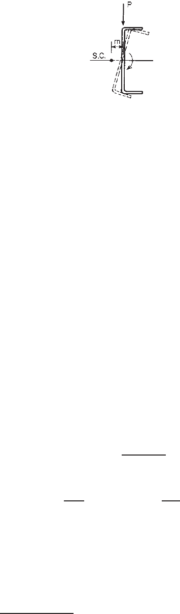
Figure 4.75 Rotation of channel section about its shear center.
(a) C-section webs with holes under stress gradient (see
Section 3.6.3 in this volume), (b) shear strength of C-section
webs with holes (Section 4.3.3.3), and (c) web crippling
strength of C-section webs with holes (Section 4.3.6.2).
These design provisions are retained in the North American
specification.
4.4 BRACING REQUIREMENTS OF BEAMS
4.4.1 Single-Channel (C-Section) Beams
4.4.1.1 Neither Flange Connected to Sheathing When
single-channel sections (C-sections) are used as beams,
adequate bracing must be provided to prevent rotation about
the shear center, as shown in Fig. 4.75, if the load is applied
in the plane of the web.
The shear center is the point through which the external
load must be applied in order to produce bending without
twisting. It is located on the axis of symmetry at a distance
m from the midplane of the web of the channel section.
The value of m can be determined approximately by Eq.
(4.181) or Eq. (4.182) for different types of flanges
∗
:
1. For channels without stiffening lips at the outer
edges,
m =
w
2
f
2w
f
+ d/3
(4.181)
2. For channels with stiffening lips at the outer edges,
m =
w
f
dt
4I
x
w
f
d + 2D
d −
4D
2
3d
(4.182)
where m = distance from shear center to midplane of
web of a channel section
w
f
= projection of flanges from inside face of web
(for channels with flanges of unequal widths,
w
f
shall be taken as the width of the wider
flange)
∗
See Appendix B for the location of the shear center for other open
sections.
BRACING REQUIREMENTS OF BEAMS 183
d = depth of channel
D = overall depth of simple lip (edge stiffener)
I
x
= moment of inertia of one channel about its
centroidal axis normal to web
(a) Bracing of Channel Beams. Since the spacing between
braces is usually larger than the s pacing of connections
required for connecting two channels to form an I-beam
(Section 8.9), each channel section may rotate slightly
between braces and results in additional stress. For this
reason, braces must be arranged and designed so that the
rotation of the beam is small and the additional stresses
will not significantly affect the load-carrying capacity of
the channel section.
The spacing and s trength of bracing required to coun-
teract the twisting tendency of channel beams have been
investigated theoretically and experimentally by Winter,
Lansing, and McCalley.
4.108
A simplified design method
has been developed on the basis of the studies of braced
and unbraced channels and verified by test data.
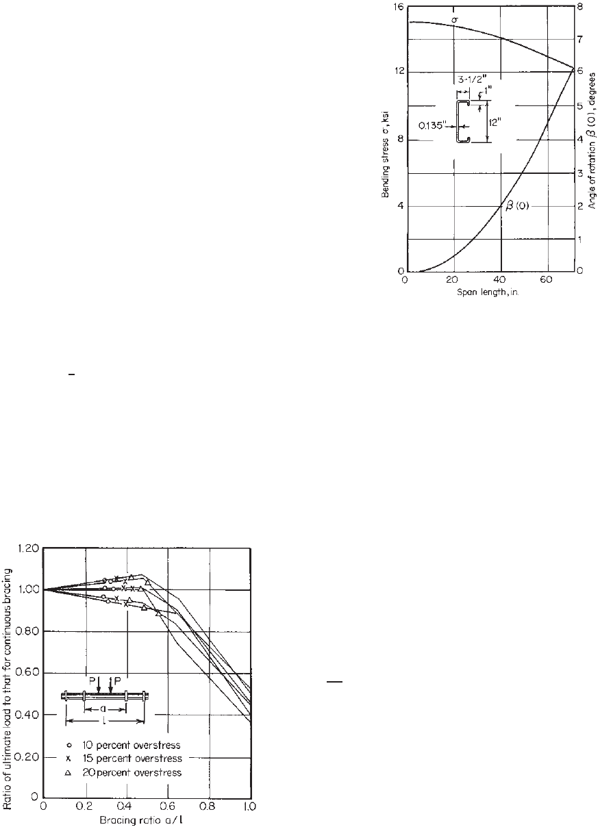
It has been found that even for impractically small spans
the unbraced channel section [depth = 12 in. (305 mm),
flange width = 3
1
2
in. (88.9 mm), depth of flange lip =
1 in. (25.4 mm), and t = 0.135 in. (3.4 mm)] made of steels
having a yield stress of 33 ksi (228 MPa, or 2320 kg/cm
2
)
can only carry less than half of the load that each continu-
ously braced channel would carry before yielding.
4.108
See
Fig. 4.76 for the bracing ratio a/l = 1.0. In addition, the
angle of rotation at the midspan e xceeds 2
◦
if the span
length is larger than 40 in. (1016 mm) (Fig. 4.77).
Figure 4.76 Effect of use of bracing.
4.108
Figure 4.77 Results of analysis for channel beam indicated.
4.108
However, as shown in Fig. 4.76, for braced channels,
even for the spacing of braces equal to 0.478 times the span
length, the ultimate loads for all practical purposes are the
same as for continuous bracing. This fact indicates that the
localized overstresses at corners do not affect the strength
of the channel sections, since plastic redistribution allows
the initially understressed portions of the section to carry
additional load. Furthermore, analyses for a great variety of
practical loading conditions show that it is unnecessary to
provide more than three braces between supports in order
to limit the overstresses to 15% of the simple bending
stress f
= Mc/I , which equals the yield stress at a load
equal to the design load times the safety factor, except that
additional bracing should be provided at the location of
a concentrated load.
4.108
This criterion has been used in
the past as a basis in the development of the earlier AISI
Specifications for a minimum number of braces. The same
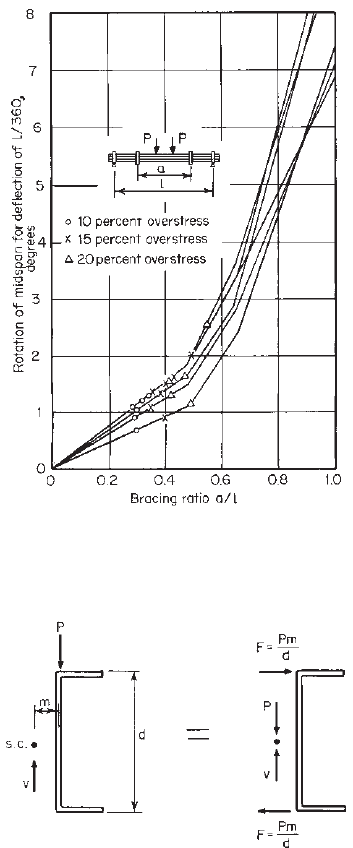
study also showed that for the 15% limitation of overstress
the rotation of the section at midspan for a deflection of
1
360
of the span length under design load would not exceed
1.5
◦
, as shown in Fig. 4.78.
The above discussion dealt with the number of braces
required to limit the additional stress induced by the
twisting of channels between braces. The lateral force to
be resisted by bracing can be determined by calculating the
reaction of a continuous beam consisting of half a channel
loaded by a horizontal force F = Pm/d since the load P
applied in the plane of the web is equivalent to the same
load P applied at the shear center plus two forces applied
at both flanges, as shown in Fig. 4.79.
184 4 FLEXURAL MEMBERS
Figure 4.78 Rotations for load resulting in central vertical
deflections equal to span/360.
4.108
Figure 4.79 Lateral force for design of brace for channels.
Based on the research work and practical considerations,
the following AISI design criteria have been developed and
included in the AISI Specifications during the period from
1956 through 1996 for bracing single-channel beams when
they are loaded in the plane of the web and neither flange
is braced by deck or other means:
Braces are to be attached to both the top and botto m flanges
of the section at the ends and at intervals not greater than
one-quarter of the span length in such a manner as to prevent
tipping at the ends and lateral deflection of either flange in
either direction at intermediate braces. Additional bracing is
to be placed at or near the center of the loaded l engt h if one-
third or more of the total load is concentrated over a length of
one-twelfth or less of the span of the beam. However, when
all loads and reactions on a beam are transmitted through
members which frame into the section in such a manner as to
effectively restrain the section against the rotation and lateral
displacement, no additional braces will be required.
In the early 1990s, beam tests conducted by Ellifritt,
Sputo, and Haynes
4.186
showed that for typical sections
a midspan brace may reduce service load horizontal
deflections and rotations by as much as 80% when
compared to a completely unbraced beam. However, the
restraining effect of braces may change the failure mode
from lateral–torsional buckling to distortional buckling of
the flange and lip at a brace point. The natural tendency
of the member under vertical load is to twist and translate
in such a manner as to relieve the compression on the
lip. When such movement is restrained by intermediate
braces, the compression on the stiffening lip is not relieved
and may increase. In this case, distortional buckling
may occur at loads lower than that predicted by the
lateral–torsional buckling equations of Section C3.1.2 of
the AISI Specification.
The same research
4.186
has also shown that the AISI
lateral–torsional buckling equations predict loads which are
conservative for cases where only one midspan brace is
used but may be unconservative where more than one inter-
mediate brace is used. Based on such research findings,
Section D3.2.2 of the AISI specification was revised in 1996
to eliminate the requirement of quarterpoint bracing. Conse-
quently Section D3.2.2 of the 1996 edition of the AISI
Specification included the following three requirements for
spacing of braces:
1. Braces shall be designed to avoid local crippling at the
points of attachment to the member.
2. When braces are provided, they shall be attached in such
a manner as to effectively restrain the section against
lateral deflection of both flanges at the ends and at any
intermediate brace points.
3. When all loads and reactions on a beam are transmitted
through members which frame into the section in such
a manner as to effectively restrain the section against
torsional rotation and lateral displacement, no additional
braces will be required except those required for strength
according to Section C3.1.2 of the Specification.
The above requirements 2 and 3 are retained in Section
D3.2.1 of the North American Specification with minor
editorial revisions.
(b) Effect of Slope and Eccentricity. The foregoing discus-
sion dealt only with a simple case, for which the gravity
load is applied in the plane of the web of a horizontal beam
as shown Fig. 4.79. For general design practices, the applied