Yu W., LaBoube R.A. Cold-Formed Steel Design
Подождите немного. Документ загружается.

TORSIONAL BUCKLING AND FLEXURAL–TORSIONAL BUCKLING 195
Considering the boundary conditions for a member with
completely fixed ends, that is, at z = 0, L,
u = v = φ = 0 u
= v
= φ
= 0 (5.11)
and for a member with hinged ends, that is, at z = 0, L,
u = v = φ = 0 u
= v
= φ
= 0 (5.12)
Equations (5.8)–(5.10) result in the following characteristic
equation:
r
2
0
(
P
cr
− P
x
)
P
cr
− P
y
(
P
cr
− P
z
)
−
(
P
cr
)
2
(
y
0
)
2
(
P
cr
− P
x
)
− (P
cr
)
2
(x
0
)
2
(P
cr
− P
y
) = 0 (5.13)
where the Euler flexural buckling load about the x axis is
given as
P
x
=
π
2
EI
x
(
K
x
L
x
)
2
(5.14)
the Euler flexural buckling load about the y axis as
P
y
=
π
2
EI
y
K
y
L
y
2
(5.15)
the torsional buckling load about the z axis as
P
z
=
π
2
EC
w
(
K
t
L
t
)
2
+ GJ
1
r
2
0
(5.16)
and KL is the effective length of the column; theoretically,
for hinged ends K = 1, and for fixed ends K = 0.5.
The buckling mode of the column can be determined by
Eq. (5.13). The critical buckling load is the smallest value of
the three roots of P
cr
. The following discussion is intended
to indicate the possible buckling mode for various types of
cross section.
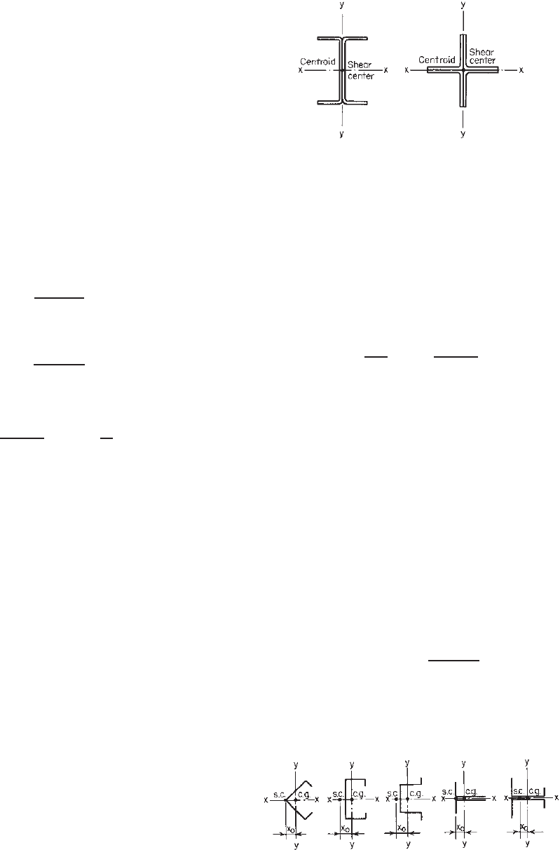
5.4.1 Doubly Symmetric Shapes
For a doubly symmetric shape, such as an I-section or a
cruciform, the shear center coincides with the centroid of
the section (Fig. 5.5), that is,
x
0
= y
0
= 0 (5.17)
For this case, the characteristic equation (5.13) becomes
(P
cr
− P
x
)(P
cr
− P
y
)(P
cr
− P
z
) = 0 (5.18)
The critical buckling load is the lowest value of the
following three solutions:
(P
cr
)
1
= P
x
(5.19)
(P
cr
)
2
= P
y
(5.20)
(P
cr
)
3
= P
z
(5.21)
Figure 5.5 Doubly symmetric shapes.
An inspection of the above possible buckling loads indi-
cates that for doubly symmetric sections the column fails
either in pure bending or in pure torsion, depending on
the column length and the s hape of the section. Usually
compression members are so proportioned that they are
not subject to torsional buckling. However, if the designer
wishes to evaluate the torsional buckling stress σ
t
,the
following formula based on Eq. (5.16) can be used:
σ
t
=
1
Ar
2
0
GJ +
π
2
EC
w
(
K
t
L
t
)
2
(5.22)
The critical stress for flexural buckling was discussed in
Section 5.3.
5.4.2 Singly Symmetric Shapes
Angles, channels (C-sections), hat sections, T-sections,
and I-sections with unequal flanges (Fig. 5.6) are singly
symmetric shapes. If the x axis is the axis of symmetry,
the distance y
0
between the shear center and the centroid in
the direction of the y axis is equal to zero. Equation (5.13)
then reduces to
P
cr
− P
y
r
2
0
(
P
cr
− P
x
)(
P
cr
− P
z
)
−
(
P
cr
x
0
)
2
= 0
(5.23)
For this case, one of the solutions is
(
P
cr
)
1
= P
y
=
π
2
EI
y
K
y
L
y
2
(5.24)
which is the critical flexural buckling load about the y axis.
The other two solutions for the flexural–torsional buckling
Figure 5.6 Singly symmetric shapes.
196 5 COMPRESSION MEMBERS
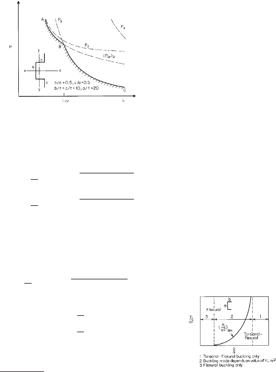
Figure 5.7 Comparison of P
cr
with P
x
,P
y
,andP
z
for hat
section (K
x
L
x
= K
y
L
y
= K
t
L
t
= L).
load can be obtained by solving the following quadratic
equation:
r
2
0
(
P
cr
− P
x
)(
P
cr
− P
z
)
−
(
P
cr
x
0
)
2
= 0 (5.25)
Letting β = 1 − (x
0
/r
0
)
2
,
(
P
cr
)
2
=
1
2β
(P
x
− P
z
) +
(
P
x
− P
z
)
2
− 4βP
x
P
z
(5.26)
(
P
cr
)
3
=
1
2β
(P
x
+ P
z
) −
(
P
x
+ P
z
)
2
− 4βP
x
P
z
(5.27)
Because (P
cr
)
3
is smaller than (P
cr
)
2
, Eq. (5.27) can be
used as the critical flexural–torsional buckling load, which
is always smaller than P
x
and P
z
, but it may be either
smallerorlargerthanP
y
[Eq. (5.24)] (Fig. 5.7).
Dividing Eq. (5.27) by the total cross-sectional area
A, the following equation can be obtained for the elastic
flexural–torsional buckling stress:
σ
TFO
=
1
2β
[(σ
ex
+ σ
t
) −
(σ
ex
+ σ
t
)
2
− 4βσ
ex
σ
t
] (5.28)
where σ
TFO
is the elastic flexural–torsional buckling stress
and
σ
ex
=
P
x
A
(5.29)
σ
t
=
P
z
A
(5.30)
In summary, it can be seen that a singly symmetric
section may buckle either in bending about the y axis
∗
or in flexural–torsional buckling (i.e., bending about the x
∗
It is assumed that the section is symmetrical about the x axis.
axis and twisting about the shear center), depending on the
dimensions of the section and the effective column length.
For the selected hat section used in Fig. 5.7, the critical
length L
cr
, which divides the flexural buckling mode and
the flexural–torsional buckling mode, can be determined by
solving P
y
= (P
cr
)
3
. This means that if the effective length
is shorter than its critical length, the flexural–torsional
buckling load (P
cr
)
3
, represented by curve AB, will govern
the design. Otherwise, if the effective length is longer
than the critical length, the load-carrying capacity of the
given member is limited by the flexural buckling load P
y
,
represented by curve BC. The same is true for other types
of singly symmetric shapes, such as angles, channels, T-
sections, and I-sections having unequal flanges.
In view of the fact that the evaluation of the critical
flexural–torsional buckling load is more complex as
compared with the calculation of the Euler load, design
charts, based on analytical and experimental investiga-
tions, have been developed for several commonly used
sections,
5.1,1.159
from which we can determine whether a
given section will buckle in the flexural–torsional mode.
Such a typical curve is shown in Fig. 5.8 for a channel
section. If a column s ection is so proportioned that
flexural–torsional buckling will not occur for the given
length, the design of such a compression member can then
be limited to considering only flexural, local, or distortional
buckling. Otherwise, flexural–torsional buckling must also
be considered.
As indicated in Fig. 5.8, the possibility of overall column
buckling of a singly symmetric section a bout the x axis
may be considered for three different cases. Case 1 is
for flexural–torsional buckling only. This particular case is
characterized by sections for which I
y
>I
x
.WhenI
y
<I
x
,
the section will fail either in case 2 or in case 3. In
case 2, the channel will buckle in either the flexural or
the flexural–torsional mode, depending on the specific ratio
of b/a and the parameter tL/a
2
,whereb is the flange width,
a is the depth of the web element, t is the thickness, and
L is the effective length. For a given channel section and
Figure 5.8 Buckling mode for channel section.
5.2
TORSIONAL BUCKLING AND FLEXURAL–TORSIONAL BUCKLING 197
column length, if the value of tL/a
2
is above the (tL/a
2
)
lim
curve, the section will fail in the flexural buckling mode.
Otherwise it will fail in the flexural–torsional buckling
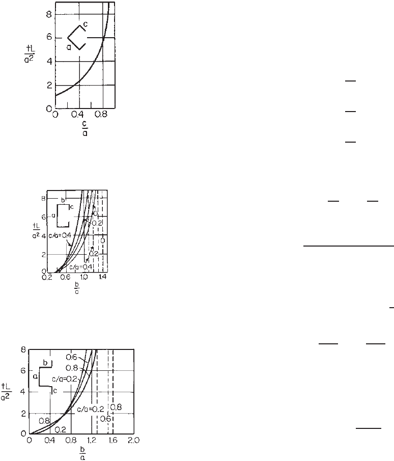
mode. In case 3, the section will always fail in the flexural
mode, regardless of the value of tL/a
2
. The buckling mode
curves for angles, channels, and hat sections are shown in
Figs. 5.9–5.11. These curves apply only to compatible end
conditions, that is,
K
x
L
x
= K
y
L
y
= K
t
L
t
= L
Figure 5.9 Buckling mode curve for angles.
5.2
Figure 5.10 Buckling mode curves for channels.
5.2
Figure 5.11 Buckling mode curves for hat sections.
5.2
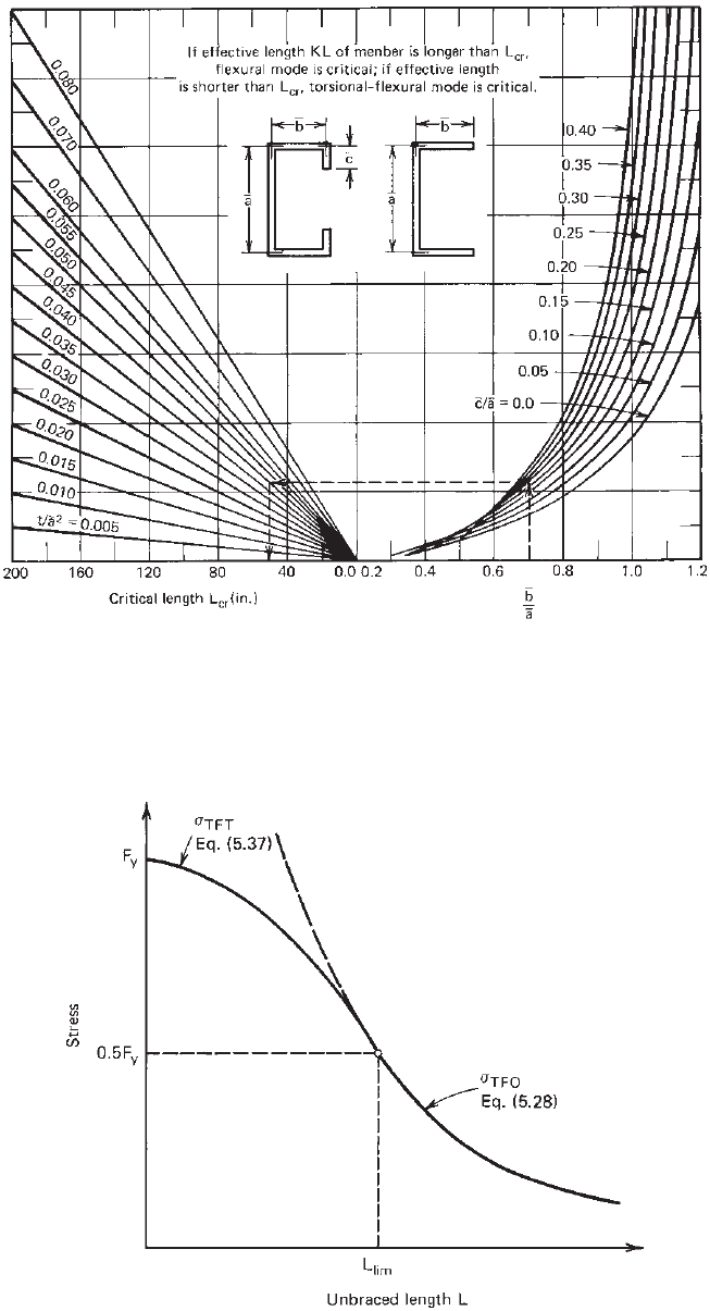
In Part VII of the 1996 edition of the AISI Design
Manual,
1.159
a set of design charts such as Fig. 5.12 were
provided for determining the critical length for angles,
channels, and hat sections. From this type of graphic design
aid, the critical length can be obtained directly according
to the dimensions and shapes of the member.
The preceding discussion deals with flexural–torsional
buckling in the elastic range for which the compression
stress is less than the proportional limit. Members of small
or moderate slenderness will buckle at a stress lower than
the value given by the elastic theory if the computed critical
buckling stress exceeds the proportional limit.
Similar to the case of flexural buckling, the inelastic
flexural–torsional buckling load may be obtained from
the elastic equations by replacing E with E
t
and G with
G(E
t
/E ), where E
t
is the tangent modulus, which depends
on the effective stress–strain relationship of the entire cross
section, that is, for inelastic flexural–torsional buckling:
(
P
x
)
T
=
E
t
E
P
x
(5.31)
(
P
z
)
T
=
E
t
E
P
z
(5.32)
(
P
cr
)
T
=
E
t
E
P
cr
(5.33)
With regard to the determination of E
t
, Bleich
3.3
indicates
that
E
t
= CE
σ
F
y
1 −
σ
F
y
(5.34)
where
C =
1
σ
pr
/F
y
1 − σ
pr
/F
y
(5.35)
F
y
and σ
pr
being the yield stress and proportional limit of
the steel, respectively. The values of C obtained from an
experimental study
5.2
ranged from 3.7 to 5.1. Based on Eq.
(5.34) and using C = 4 (assuming σ
pr
=
1
2
F
y
), the tangent
modulus E
t
for the inelastic buckling stress is given by
E
t
= 4E
σ
TFT
F
y
1 −
σ
TFT
F
y
(5.36)
where σ
TFT
is the inelastic flexural–torsional buckling
stress. Substituting the above relationship into Eq. (5.33),
the following equation for inelastic flexural–torsional buck-
ling stress can be obtained:
σ
TFT
= F
y
1 −
F
y
4σ
TFO
(5.37)
in which σ
TFO
is the elastic flexural–torsional buckling
stress determined by Eq. (5.28). Equation (5.37) is shown
graphically in Fig. 5.13.
198 5 COMPRESSION MEMBERS
Figure 5.12 AISI chart for determining critical length of channels.
1.159
Figure 5.13 Maximum stress for flexural–torsional buckling.
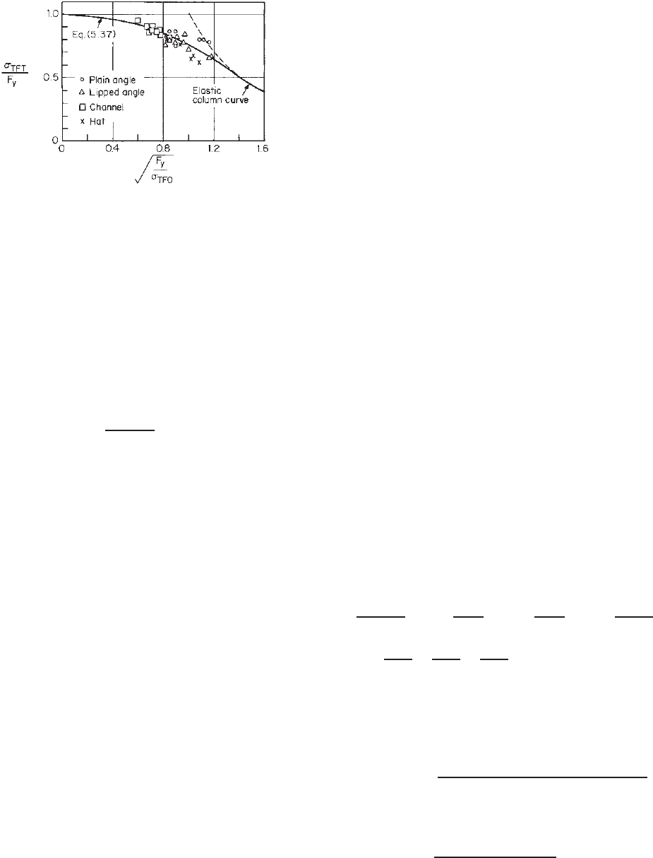
TORSIONAL BUCKLING AND FLEXURAL–TORSIONAL BUCKLING 199
Figure 5.14 Correleation of analytical and experimental
investigations.
5.2
To verify the design procedure described above, a total
of eight columns were tested for elastic flexural–torsional
buckling a nd 30 columns were tested for inelastic
flexural–torsional buckling at Cornell University.
5.2
The
results of the inelastic column tests are compared with Eq.
(5.37) in Fig. 5.14.
Similar to the case for flexural column buckling, Eq.
(5.37) has been used in the AISI specification up to 1996. In
the 1996 edition of the specification, the nominal inelastic
flexural–torsional buckling stress was computed by Eq.
(5.7a), in which λ
c
=
F
y
/σ
TFO
.
Following an evaluation of the test results of angles
reported by Madugula, Prabhu, Temple, Wilhoit, Zandonini,
and Zavellani,
5.12–5.14
Pekoz indicated in Ref. 3.17 that
angle sections are more sensitive to initial sweep than lipped
channels. It was also found that the magnitude of the initial
sweep equal to L/1000 would give reasonable results for
the specimens considered in his study. On the basis of the
findings summarized in Ref. 3.17, an out-of-straightness
of L/1000 was used in Section C5.2 of the 1996 edition
of the AISI specification for computing additional bending
moment M
y
(forASD)orM
uy
(for LRFD). Based on
the research findings of Popvic, Hancock, and Rasmussen,
reported in Ref. 5.100, the North American Specification
uses the additional bending moment due to an out-of-
straightness of L/1000 only for singly symmetric unstiff-
ened angles for which the effective area at s tress F
y
is less
than the full unreduced cross-sectional area. For the struc-
tural strengths of angles and channels, additional informa-
tion can be found in Refs. 5.15, 5.19, 5.101, 5.102, 5.110,
5.117, 5.119, 5.123, 5.125, 5.128, 5.131–5.134, 5.137, and
5.156–5.173.
5.4.3 Point-Symmetric Sections
A point-symmetric section is defined as a section symmet-
rical about a point (centroid), such as a Z-section having
equal flanges or a cruciform section.
5.17
For this case the
shear center coincides with the centroid and x
0
= y
0
= 0.
Similar to doubly symmetric sections, Eq. (5.13)
leads to
(P
cr
− P
x
)(P
cr
− P
y
)(P
cr
− P
z
) = 0 (5.38)
Therefore the section may fail in either bending (P
x
or P
y
)
or twisting (P
z
), depending on the shape of the section and
the c olumn length. It should be noted that the x and y axes
are principal axes.
Although the curve for determining the buckling mode
is not available for Z-sections, a limited investigation has
been carried out at Cornell.
5.2
It was found that plain
and lipped Z-sections will always fail as simple Euler
columns regardless of their size and shape, provided that the
effective length for bending about the minor principal axis
is equal to or greater than the effective length for twisting.
The structural strengths of point-symmetric Z-sections have
been discussed by Rasmussen
5.153,5.154
and Thottunkal and
Ramseyer.
5.174
5.4.4 Nonsymmetric Sections
If the open section has no symmetry either about an axis or
about a point, all three possible buckling loads P
cr
are of the
flexural–torsional type. The lowest value of P
cr
is always
less than the lowest of the three values P
x
, P
y
,andP
z
.
In the design of compact nonsymmetric sections,
the elastic flexural–torsional buckling stress σ
TFO
may
be computed from the following equation by trial and
error
1.159,1.349
:
σ
3
TFO
σ
ex
σ
ey
σ
t
α −
σ
2
TFO
σ
ey
σ
t
γ −
σ
2
TFO
σ
ex
σ
t
β −
σ
2
TFO
σ
ex
σ
ey
+
σ
TFO
σ
ex
+
σ
TFO
σ
ey
+
σ
TFO
σ
t
= 1 (5.39)
In the calculation, the following equation may be used for
the first approximation:
σ
TFO
=[(σ
ex
σ
ey
+ σ
ex
σ
t
+ σ
ey
σ
t
)
−
(σ
ex
σ
ey
+ σ
ex
σ
t
+ σ
ey
σ
t
)
2
−4(σ
ex
σ
ey
σ
t
)(γ σ
ex
+ βσ
ey
+ σ
t
)]
×
1
2
γσ
ex
+ βσ
ey
+ σ
t
(5.40)
200 5 COMPRESSION MEMBERS
where
σ
ex
=
π
2
E
(
K
x
L
x
/r
x
)
2
(5.41)
σ
ey
=
π
2
E
K
y
L
y
/r
y
2
(5.42)
σ
t
=
1
Ar
2
0
GJ +
π
2
EC
w
(
K
t
L
t
)
2
(5.43)
and
E = modulus of elasticity, =29.5 × 10
3
ksi
(203 GPa, or 2.07×10
6
kg/cm
2
)
KL = effective length of compression member
r
x
= radius of gyration of cross section about x
axis
r
y
= radius of gyration of cross section about y
axis
A = cross-sectional area
r
0
=
r
2
x
+ r
2
y
+ x
2
0
+ y
2
0
G = shear modulus, =11.3 × 10
3
ksi (78 GPa, or
794×10
3
kg/cm
2
)
J = St. Venant torsion constant of cross section
α = 1 − (x
0
/r
0
)
2
–(y
0
/r
0
)
2
β = 1 − (x
0
/r
0
)
2
γ = 1 − (y
0
/r
0
)
2
x
0
= distance from shear center to centroid along
principal x axis
y
0
= distance from shear center to centroid along
principal y axis
C
w
= warping constant of torsion of cross section
(Appendix B)
5.5 EFFECT OF LOCAL BUCKLING
ON COLUMN STRENGTH
Cold-formed steel compression members may be so propor-
tioned that local buckling of individual component plates
occurs before the applied load reaches the overall collapse
load of the column. The interaction effect of the local and
overall column buckling may result in a reduction of the
overall column strength.
In general, the influence of local buckling on column
strength depends on the following factors:
1. Shape of cross section
2. Slenderness ratio of column
3. Type of governing overall column buckling (flex-
ural buckling, torsional buckling, or flexural–torsional
buckling)
4. Type of steel used and its mechanical properties
5. Influence of cold work
6. Effect of imperfection
7. Effect of welding
8. Effect of residual stress
9. Interaction between plane components
10. Effect of perforations
During the past 60 years, investigations on the interac-
tion of local and overall buckling in metal columns have
been conducted by numerous researchers.
1.11,3.70,5.20–5.63
Different approaches have been suggested for analysis and
design of columns.
5.5.1 Q -Factor Method
The effect of local buckling on column strength was consid-
ered in the AISI specification during the period from 1946
through 1986 by using a form factor Q in the determination
of allowable stress for the design of axially loaded compres-
sion members. Winter and Fahy were the principal contrib-
utors to the development of this Q factor. Accumulated
experience has proved that the use of such a form factor as
discussed below is a convenient and simple method for the
design of cold-formed steel columns.
1.161
As previously discussed, if an axially loaded short
column has a compact cross section, it will fail in yielding
rather than buckling, and the maximum load P can be deter-
mined as follows:
P = AF
y
(5.44)
where A = full cross-sectional area
F
y
= yield stress of steel
However, for the same length of the column, if the w/t
ratios of compression elements are relatively large, the
member may fail through local buckling at a stress less
than F
y
. Assuming the reduced stress is QF
y
instead of F
y
,
then
P = A(QF
y
) (5.45)
where Q is a form factor which is less than unity, repre-
senting the weakening influence due to local buckling.
From the above two equations it can be seen that the
effect of local buckling on column strength can be consid-
ered for columns that will fail in local buckling by merely
replacing F
y
by QF
y
. The same is true for columns having
moderate KL/r ratios.
The value of form factor Q depends on the form or shape
of the section. It can be computed as follows for various
types of sections:
1. Members Composed Entirely of Stiffened
Elements. When a short compression member
is composed entirely of stiffened elements such as
DISTORTIONAL BUCKLING STRENGTH OF COMPRESSION MEMBERS 201
the tubular member shown in Fig. 5.1a, it will fail
when the edge stress of the stiffened elements reaches
the yield stress. Using the effective width concept,
the column will fail under a load
P = A
eff
F
y
(5.46)
where A
eff
is the sum of the effective areas of all
stiffened elements.
Comparing the above equation with Eq. (5.45), it
is obvious that
Q
a
=
A
eff
A
(5.47)
where Q
a
is the area factor.
2. Members Composed Entirely of Unstiffened
Elements. If a short compression member is
composed entirely of unstiffened elements, it will
buckle locally under a load
P = Aσ
cr
(5.48)
where σ
cr
is the critical local buckling stress of the
unstiffened element.
Comparing the above equation again with Eq.
(5.45), it is found that
Q
s
=
σ
cr
F
y
=
F
c
F
(5.49)
where Q
s
= stress factor
F
c
= allowable compressive stress
F = basic design stress (0.60F
y
)forthe
ASD method
3. Members Composed of both Stiffened and Unstiff-
ened Elements. If a short compression member is
composed of both stiffened and unstiffened elements
as shown in Fig. 5.1c,
∗
the useful limit of the member
may be assumed to be reached when the stress in the
weakest unstiffened element reaches the critical local
buckling stress σ
cr
. In this case, the effective area A
eff
will consist of the full area of all unstiffened elements
and the sum of the reduced or effective areas of all
stiffened elements. That is,
P = A
eff
σ
cr
(5.50)
Comparing the above equation with Eq. (5.45),
Q = A
eff
σ
cr
AF
y
=
A
eff
A
σ
cr
F
y
=
A
eff
A
F
c
F
= Q
a
Q
s
(5.51)
∗
The stiffeners are considered as unstiffened elements.
where Q = form factor
Q
a
= area factor
Q
s
= stress factor
5.5.2 Unified Approach
Even though the Q -factor method has been used success-
fully in the past for the design of cold-formed steel
compression members, additional investigations at Cornell
University and other institutions have shown that this
method is capable of improvement.
3.17,5.26–5.28,5.49
On the
basis of test results and analytical studies of DeWolf, Pekoz,
Winter, Kalyanaraman, and Loh, Pekoz shows in Ref. 3.17
that the Q-factor approach can be unconservative for
compression members having stiffened elements w ith large
width-to-thickness ratios, particularly for those members
having slenderness ratios in the neighborhood of 100. On
the other hand, the Q-f actor method gives very conservative
results for I-sections having unstiffened flanges, especially
for columns with small slenderness ratios. Consequently,
the Q factor was eliminated in the 1986 edition of the AISI
Specification. In order to reflect the effect of local buckling
on column strength, the nominal column load is determined
by the governing critical buckling stress and the effective
area A
e
instead of the full sectional area. When A
e
cannot
be calculated, such as when the compression member has
dimensions or geometry outside the range of applicability
of the generalized effective width equations of the AISI
Specification, the effective area A
e
can be determined exper-
imentally by stub column tests as described in Ref. 3.17.
For C- and Z-shapes and single-angle sections with unstiff-
ened flanges, the nominal column load has been limited
by the column buckling load, which is calculated by the
local buckling stress of the unstiffened flange and the area
of the full, unreduced cross section. This requirement was
included in Section C 4(b) of the 1986 edition of the AISI
Specification. It was deleted in 1996 on the basis of the
study conducted by Rasmussen and Hancock (Refs. 5.101
and 5.102).
The current North American design provisions are
presented in Section 5.8 followed by design examples.
5.6 DISTORTIONAL BUCKLING STRENGTH
OF COMPRESSION MEMBERS
5.6.1 Research Work
The distortional buckling mode for flexural members was
discussed in Section 4.2.4. For column design, flange
distortional buckling is also one of the important failure
modes for open cross-sectional compression members
having edge-stiffened flanges as shown in Fig. 5.15. This
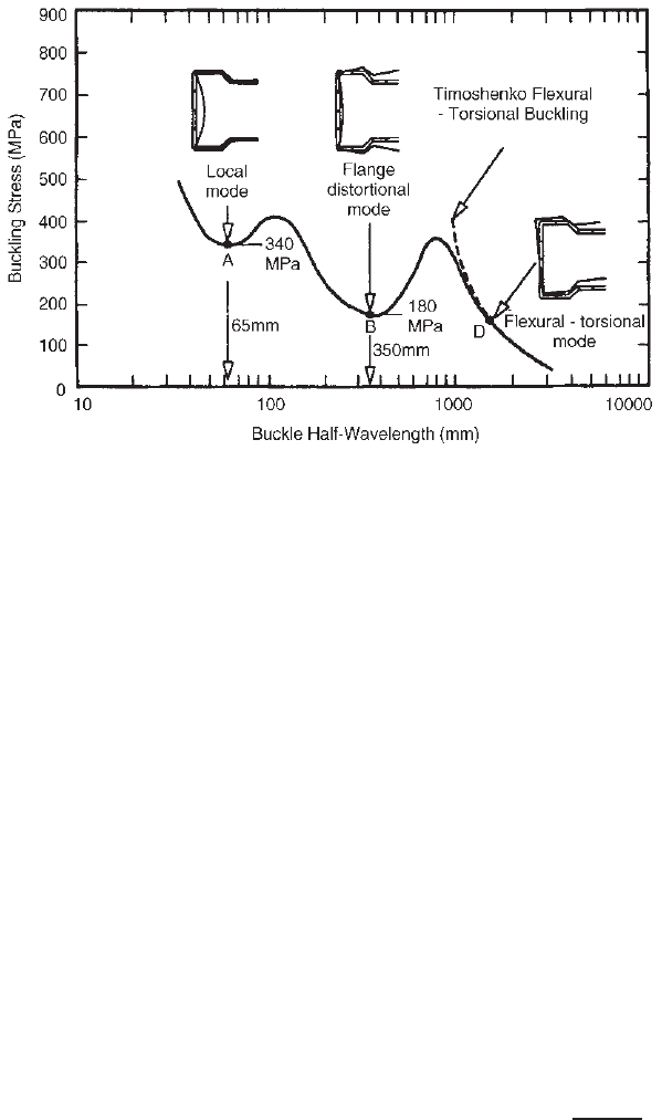
202 5 COMPRESSION MEMBERS
Figure 5.15 Rack section column buckling stress versus half wavelength for concentric
compression.
1.69
type of buckling mode involves the rotation of each flange
and lip about the flange–web junction.
During the past three decades, the distortional buckling
modes of compression members have been studied
by Hancock,
5.108,1.358
Lau and Hancock,
5.109–5.111
Charnvarnichborikarn and Polyzois,
5.112
Kwon and
Hancock,
5.113,5.114
Hancock, Kwon, and Bernard
5.115
Schafer,
3.195
Davies, Jiang, and Ungureanu,
4.168
Bambach,
Merrick, and Hancock,
3.173
and others. Earlier research
findings were well summarized by Hancock in Ref. 1.69.
In the same publication, Hancock also discussed the
background information on the 1996 Australian design
provisions for distortional buckling of flexural members
and compression members.
Since 1999, additional studies of distortional buck-
ling of compression members have been conducted by
Kesti and Davies,
5.175
Schafer,
5.176
Young and Yan,
5.177
Camotim, Dinis, and Silvestre,
5.178–5.180,5.183,5.184, 5.186,5.187
Ranawaka and Mahendran,
5.181
Tovar and Sputo,
5.182
Rao
and Kalyanaraman,
5.185
and others. Some of the research
findings are summarized in Refs. 1.346, 1.383, and 1.412.
For the analytical model used for development of design
provisions, see Section 4.2.4.
5.6.2 Design Criteria for Distortional Buckling
Strength of Open-Section Compression Members
In 2007, the North American Specification included
Appendix I for the design of cold-formed steel structural
members using the DSM. At the same time, a new Section
4.2 was added in the main part of the specification for
determining the distortional buckling strength of I-, Z-, C-,
hat, and other open cross-section compression members
having edge-stiffened flanges. An excerpt of Section 4.2
of the 2007 edition of the North American specification is
included here in Section 5.8.
5.7 EFFECT OF COLD WORK ON COLUMN
BUCKLING
The discussions in Sections 5.1–5.6 were based on the
assumption that the compression members have uniform
mechanical properties over the entire cross section.
However, as shown in Fig. 2.3, the yield stress and tensile
strength of the material vary from place to place in the
cross section due to the cold work of forming. The column
strength of the axially loaded compression member with
nonuniform mechanical properties throughout the cross
section may be predicted by Eq. (5.52) on the basis of the
tangent modulus theory if we subdivide the cross section
into j subareas, for which each subarea has a constant
material property
2.14,2.17,5.64,5.65
:
σ
T
=
π
2
A(KL)
2
j
i=1
E
ti
I
i
(5.52)
where E
ti
= tangent modulus of i th subarea at a
particular value of strain
I
i
= moment of inertia of i th subarea about
neutral axis of total cross section
In order to investigate the strength of cold-formed
compression members subjected to an axial load, six spec-
imens made of channels back to back have been tested
NORTH AMERICAN DESIGN FORMULAS FOR CONCENTRICALLY LOADED COMPRESSION MEMBERS 203
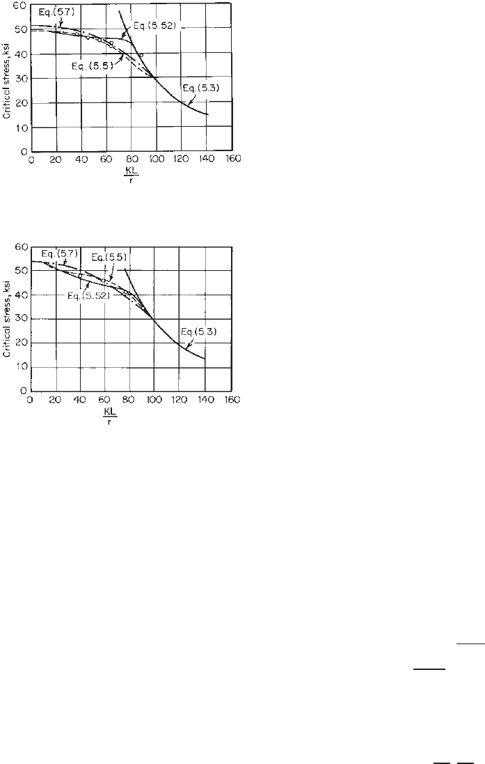
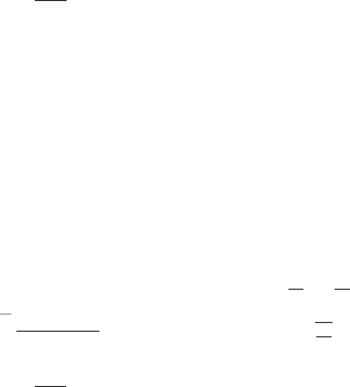
Figure 5.16 Comparison of column curves for channel
sections.
2.17
Figure 5.17 Comparison of column curves for joist chord
sections.
2.17
by Karren and Winter at Cornell University.
2.14,2.17
The
test data are compared graphically with Eqs. (5.5), (5.7),
and (5.52) in Fig. 5.16. In addition, four pairs of joist
sections have also been tested at Cornell. Results of tests
are compared in Fig. 5.17.
2.17
Based on the test data shown in Figs. 5.16 and 5.17,
2.17
it may be concluded that with the exception of two channel
tests Eq. (5.52) seems to produce a somewhat better corre-
lation because it considers the variable material properties
over the cross section. Equations (5.5) and (5.7), based on
the average of compressive and tensile yield stresses, also
predict satisfactory column buckling stress in the inelastic
range with reasonable accuracy, particularly for columns
with a slenderness ratio around 60. Equation (5.7) could
provide a lower boundary for column buckling stress if the
tensile yield stress is to be used.
2.14
5.8 NORTH AMERICAN DESIGN FORMULAS
FOR CONCENTRICALLY LOADED
COMPRESSION MEMBERS
Based on the discussions of Sections 5.2–5.6, appropriate
design provisions are included in the North American
specification for the design of axially loaded compression
members. The following excerpts are adapted from Section
C4 of the 2007 edition of the North American specification
for the ASD, LRFD, and LSD methods:
C4 Concentrically Loaded Compression Members
The available axial strength [factored compressive resistance]
shall be the smaller of the values calculated in accordance with
this Section and Sections 5.10 and 5.13, where applicable.
C4.1 Nominal Strength for Yielding, Flexural,
Flexural–Torsional, and Torsional Buckling
Section C4.1 shall apply to members in which t he resultant of
all loads acting on the member is an axial load passing through
the centroid of the effective section calculated at the stress, F
n
,
defined in Section C4. 1 of the Specification.
(a) The nominal axi al strength [compressive resistance], P
n
,
shall be calculated in accordance with Eq. (5.53). The safety
factor and resistance factors in this section of the specifica-
tion shall be used to determine the allowable axial strength
or design axial strength [factored compressive resistance] in
accordance with the applicable design method in Section 3.3.1,
3.3.2, or 3.3.3:
P
n
= A
e
F
n
(5.53)
c
= 1.80 (ASD)
φ
c
=
0.85 (LRFD)
0.80 (LSD)
where A
e
is the effective area calculated at stress F
n
.For
sections with circular holes, A
e
is determined in accordance
with Section B2.2(a), subject to the limitations of that section.
If the number of holes in the effective length region times the
hole diameter divided by the effective length does not exceed
0.015, it is permitted to determine A
e
by ignoring the holes. For
closed cylindrical tubular members, A
e
is provided in Section
C4.1.5. F
n
shall be calculated as follows:
F
n
=
⎧
⎪
⎪
⎨
⎪
⎪
⎩
0.658
λ
2
c
F
y
for λ
c
≤ 1.5 (5.54)
0.877
λ
2
c
F
y
for λ
c
> 1.5 (5.55)
where λ
c
=
F
y
/F
e
and F
e
is th e least of the applicable
elastic flexural, torsional, and flexural–torsional buckling stress
determined in accordance with Sections C4.1.1–C4.1.5.
(b) C oncentrically loaded angle sections shall be designed for
an additional bending moment as specified in the definitions of
M
x
, M
y
(ASD) or M
x
, M
y
(LRFDorLSD)inSectionC5.2.
C4.1.1 Sections Not Subject to Torsional or Flexural–
Torsional Buckling
For doubly symmetric sections, closed cross sections and any
other sections that can be shown not to be subjected to torsional
or flexural–torsional buckling, the elastic flexural buckling
204 5 COMPRESSION MEMBERS
stress, F
e
, shall be calculated as follows:
F
e
=
π
2
E
(KL/r)
2
(5.56)
where E = modulus of elasticity of steel
K = effective length factor
L = laterally unbraced length of member
r = radius of gyration of full, unreduced cross section
about axis of buckling
In frames where lateral stability, shear walls, attachment to
an adjacent structure having adequate lateral stability, or roof
decks secured horizontally by walls or bracing system parallel
to the plane of the frame, and in trusses, the effective length
factor, K , for compression members which do not depend upon
their own bending stiffness for lateral stability of the frame or
truss shall be taken as unity, unless analysis shows t hat the
smaller value is suitable. In a frame that depends upon its
own bending stiffness for lateral stability, the effective length,
KL, of the compression members shall be determined by a
rational method and shall not be less than the actual unbraced
length.
C4.1.2 Doubly or Singly Symmetric Sections Subject to
Torsional or Flexural–Torsional Buckling
For singly symmetric sections subject to flexural–torsional
buckling, F
e
shall be taken as the smaller of F
e
calcu-
lated in accordance with Section C4.1.1 and F
e
calculated
as follows:
F
e
=
1
2β
[
(
σ
ex
+ σ
t
)
−
(
σ
ex
+ σ
t
)
2
− 4βσ
ex
σ
t
] (5.57)
Alternatively, a conservative estimate of F
e
shall be permitted
to be calculated as follows:
F
e
=
σ
t
σ
ex
σ
t
+ σ
ex
(5.58)
where
β = 1 − (x
0
/r
0
)
2
(5.59)
and σ
t
and σ
ex
are values defined in Section C3.1.2.1. For
singly symmetric sections, the x axis shall be selected as the
axis of symmetry.
For doubly symmetric sections subject to torsional buckling,
F
e
shall be taken as the smaller of F
e
calculated in accordance
with Section C4.1.1 and F
e
= σ
t
,whereσ
t
is defined in Section
C3.1.2.1.
For singly symmetric unstiffened angle sections for which
the effective area (A
e
)atstressF
y
is equal to the unreduced
cross-sectional area (A), F
e
shall be computed using Eq. (5.56)
where r is the least radius of gyration.
C4.1.3 Point-Symmetric Sections
For point-symmetric sections, F
e
shall be taken as the leaser
of σ
t
as defined in Section C3.1.2.1 and F
e
as calculated in
Section C4.1.1 using the minor principal axis of the section.
C4.1.4 Nonsymmetric Sections
For shapes whose cross sections do not have any symmetry,
either about an axis or about a point, F
e
shall be determined
by rational analysis. Alternatively, compression members
composed of such shapes shall be permitted to be tested in
accordance with Chapter F.
C4.2 Distortional Buckling Strength [Resistance]
The provisions of this section of the Specification shall apply
to I-, Z-, C-, hat, and other open cross-sectional members that
employ flanges with edge stiffeners, with the exception of
members that are designed in accordance with Section 5.13.
The nominal axial strength [compressive resistance] shall be
calculated in accordance wi th Eqs. (5.60) and (5.61). The safety
factor and resistance factors in this section of the Specification
shall be used to determine the allowable compressive strength
or design compressive strengt h [resistance] in accordance with
the applicable design method in Section 3.3.1, 3.3.2 or 3.3.3:
c
= 1.80 (ASD)
φ
c
=
0.85 (LRFD)
0.80 (LSD)
For λ
d
≤ 0.561
P
n
= P
y
(5.60)
For λ
d
> 0.561
P
n
=
1 − 0.25
P
crd
P
y
0.6
P
crd
P
y
0.6
P
y
(5.61)
where
λ
d
=
P
y
P
crd
(5.62)
P
n
is the nominal axial strength,
P
y
= A
g
F
y
(5.63)
where A
g
= gross area of the cross section
F
y
= yield stress
and
P
crd
= A
g
F
d
(5.64)
where F
d
is the elastic distortional buckling stress calculated
in accordance with either Section C4.2(a), (b), or (c)
(a) Simplified Provision for Unrestrained C- and Z-Sections
with Simple Lip Stiffeners. For C- and Z-sections that have
no rotational restraint of the flange and that are within the
dimensional limits provided in this section of the Specifica-
tion, Eq. (5.65) shall be permitted to be used to calculate a
conservative prediction of distortional buckling stress, F
d
.See
Section C4.2(b) or C4.2(c) of the Specification for alternative
options for members outside the dimensional limits.
The following dimensional limits shall apply:
1. 50 ≤ h
o
/t ≤ 200,
2. 25 ≤ b
o
/t ≤ 100,
3. 6.25 <D/t≤ 50,