Yu W., LaBoube R.A. Cold-Formed Steel Design
Подождите немного. Документ загружается.

BRACING REQUIREMENTS OF BEAMS 185
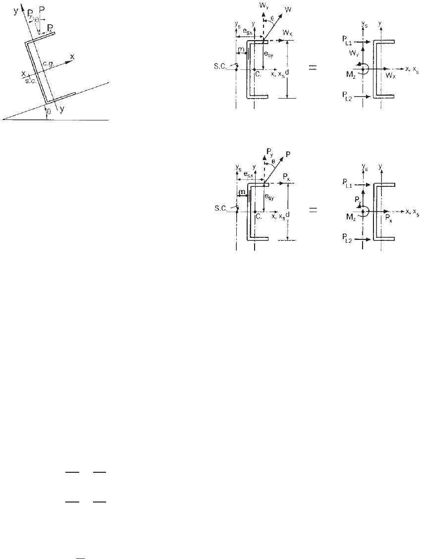
Figure 4.80 C-purlin on sloped roof.
load can be either a gravity load or an uplift load acting
at any location along the beam flange. When C-purlins are
used for sloped roofs, the top flange of the purlin is subject
to an inclined load as shown in Fig. 4.80. For this case, both
components P
x
and P
y
should be c onsidered in design.
(c) North American Design Criteria. In order to provide
a general method for determining the lateral force for
the design of braces, newly revised equations were added
in Section D3.2.1 of the North A merican Specification
for the design of C-section or channel beams.
1.343,1.345
It
is specified that each intermediate brace, at the top and
bottom flanges of C-section members, shall be designed
with resistance forces of P
L1
and P
L2
,whereP
L1
is the
brace force required on the flange which is located in
the quadrant with both x and y axes positive, P
L2
is
the brace force on the other flange. The x axis is the
centroidal axis perpendicular to the web, and the y axis
is the centroidal a xis parallel to the web. The x and y
coordinates shall be oriented such that one of the flanges
is located in the quadrant with both positive x and y axes
as shown in Fig. 4.81 for uniform load and Fig. 4.82 for
concentrated load. Consequently, for C-section members,
the brace forces P
L1
and P
L2
can be determined as follows:
1. For uniform loads (Fig. 4.81),
P
L1
= 1.5
−
W
x
2
+
M
z
d
(4.183)
P
L2
= 1.5
−
W
x
2
−
M
z
d
(4.184)
When the uniform load W acts through the midplane of
the web, that is, W
y
= W , W
x
= 0, and e
sx
= m,then
P
L1
=−P
L2
= 1.5
m
d
W (4.185)
where W
x
, W
y
= components of design load (factored
load) W parallel to the x and y axis,
respectively; W
x
and W
y
are positive
Figure 4.81 C-section member subjected to the uniform load.
Figure 4.82 C-section member subjected to a concentrated
load.
1.346
if pointing to the positive x and y
direction; respectively
W = design load (factored load) (applied
load determined in accordance with
the most critical load combinations
for ASD, LRFD, or LSD, whichever
is applicable) within a distance of
0.5a on each side of the brace
a = longitudinal distance between
centerline of braces
d = depth of section
m = distance from shear center to
midplane of web of C-section
M
z
=−W
x
e
sy
+ W
y
e
sx
, torsional moment
of W about shear center using
right-hand rule
e
sx
,e
sy
= eccentricities of load components
measured from the shear center and in
the x and y directions, respectively
It should be noted that in Eqs. (4.183)–(4.185) the
constant of 1.5 is used to account for the larger reaction
at the first interior support of a continuons beam, which
consists of half a channel loaded by a uniform horizontal
force. In addition, it considers the fact that the assumed
uniform load may not be really uniform. The Specifica-
tion adopts a conservative approach for uneven uniform
186 4 FLEXURAL MEMBERS
loading with the shift of loading location along the beam
flange.
2. For c oncentrated loads (Fig. 4.82),
P
L1
=−
P
x
2
+
M
z
d
(4.186)
P
L2
=−
P
x
2
−
M
z
d
(4.187)
When a design load (factored load) acts through the
midplane of the web, that is, P
y
= P , P
x
= 0, and
e
sx
= m,then
P
L1
=−P
L2
=
m
d
P (4.188)
where P
x
,P
y
= components of design load (factored
load) P paralle to the x and y axis,
respectively; P
x
and P
y
are positive if
pointing to the positive x and y
directions, respectively
P = design concentrated load (factored
load) within a distance of 0.3a on each
side of the brace, plus 1.4(1 - l/a)
times each design concentrated load
located farther than 0.3a but not
farther than 1.0a from the brace; the
design concentrated load (factored
load) is the applied load determined in
accordance with the most critical load
combinations for ASD, LRFD, or LSD,
whichever is applicable
l = distance from concentrated load to the
brace
M
z
=−P
x
e
sy
+ P
y
e
sx
, torsional moment of
P about shear center using right-hand
rule
Other variables are defined under 1 above for uniform loads.
General Provisions. In both items 1 and 2 above, the
bracing forces P
L1
and P
L2
are positive where restraint
is required to prevent the movement of the corresponding
flange in the negative x direction.
Where braces are provided, they shall be attached in such
a manner as to effectively restrain the section against lateral
deflection of both flanges at the ends and at any intermediate
brace points.
When all loads and reactions on a beam are transmitted
through members which frame into the section in such
a manner as to effectively restrain the section against
torsional rotation and lateral displacement, no additional
braces shall be required except those required for strength
(resistance) according to Section C3.1.2.1 of the North
American Specification.
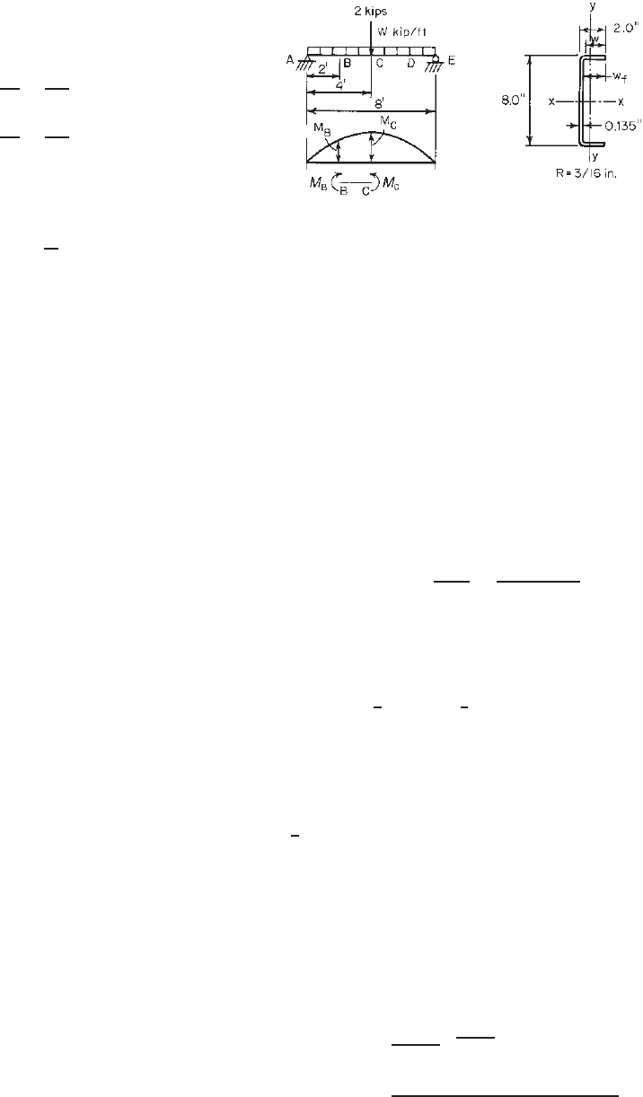
Figure 4.83 Example 4 .24.
Example 4.24 Use the ASD method to determine the
allowable uniform load and design lateral braces for the
channel section used as a simple beam shown in Fig. 4.83.
Assume that braces are attached to both top and bottom
flanges of the channel section at both ends and at intervals
equal to one-quarter of the span length. Use A1011 SS
Grade 50 steel (F
y
= 50 ksi).
SOLUTION
1. Determination of Allowable Uniform Load Based on
Section Strength. By using the design procedure illus-
trated in Example 4.1, the allowable moment based
on section strength is
M
a
=
S
e
F
y
b
=
(3.123)(50)
1.67
= 93.50 in.-kips
For the concentrated load of 2 kips, the moment at
point C is
M
C
=
1
4
PL(12) =
1
4
(2)(8)(12) = 48 in.-kips
The moment permissible for the uniform load is
M = M
a
− M
C
= 93.50 − 48
= 45.50 in.-kips
1
8
wL
2
(
12
)
= 45.50 in.-kips
w = 0.474 kip/ft including weight of beam
2. Determination of Allowable Uniform Load Based
on Lateral–Torsional Buckling Strength. Using an
interval of 24 in., the allowable moment for portion
BC (Fig. 4.83) on the basis of lateral–torsional
buckling strength (Section 4.2.3.3) can be determined
as follows: From Eq. (4.65a),
F
e
=
C
b
r
o
A
S
f
√
σ
ey
σ
t
C
b
=
12.5M
max
2.5M
max
+ 3M
1
+ 4M
2
+ 3M
3

BRACING REQUIREMENTS OF BEAMS 187
where M
max
= 93.50 in.-kips, maximum moment at
point C
M
1
= 69.11 in.-kips, at
1
/
4
point of
unbraced length
M
2
= 78.66 in.-kips, at midpoint of
unbraced length
M
3
= 86.79 in.-kips, at
3
/
4
point of
unbraced length
Therefore
C
b
=
12.5
(
93.50
)
2.5
(
93.50
)
+ 3
(
69.11
)
+ 4
(
78.66
)
+ 3
(
86.79
)
=1.15
Based on Section C3.1.2.1 of the North American
specification,
r
o
=
r
2
x
+ r
2
y
+ x
2
0
= 3.09 in.
Using the full cross-sectional area,
A = 1.554 in.
2
From Eq. (4.67),
σ
ey
=
π
2
E
K
y
L
y
/r
y
2
=
π
2
(
29,500
)
(
1 × 2 ×12/0.559
)
2
= 158.0ksi
From Eq. (4.68),
σ
t
=
1
Ar
2
o
GJ +
π
2
EC
w
(
K
t
L
t
)
2
=
1
(
1.554
)(
3.09
)
2
(
11,300
)(
0.00944
)
+
π
2
(
29,500
)(
5.56
)
(
1 × 2 ×12
)
2
= 196.60 ksi
In the above equation, the values of J and C
w
are computed from the Design Manual
1.349
or from
Appendix B in this volume. Therefore, the elastic crit-
ical lateral–torsional buckling stress is
F
e
=
(
1.15
)(
3.09
)(
1.554
)
3.269
(
158.0
)(
196.60
)
= 297.72 ksi
For the yield stress of steel, F
y
= 50 ksi,
0.56F
y
= 28.00 ksi 2.78F
y
= 139.00 ksi
Since F
e
> 2.78F
y
, the member segment is not subject
to lateral–torsional buckling at a bending moment
equal to M
y
. The nominal moment should be deter-
mined in accordance with Section 4.2.2.1 in this
volume or Section C3.1.1(a) of the North American
specification as follows:
M
n
= S
e
F
y
= (3.123)(50) = 156.15 in.-kips
The allowable moment is
M
a
=
M
n
b
=
156.15
1.67
= 93.50 in.-kips
Because the above allowable moment for lateral–
torsional buckling is the same as that allowed for
section strength in item 1, the allowable uniform
load is
w = 0.474 kip/ft including weight of beam
3. Design of Braces. Assuming that the gravity loads are
applied through the midplane of the web, based on
Eqs. (4.185) and (4.188), the braces used at midspan
should be designed to resist the following forces P
L1
and P
L2
:
P
L1
=−P
L2
= 1.5
m
d
W +
m
d
P
where
d = 8.0in.
m =
w
2
f
2w
f
+ d/3
=
(
1.865
)
2
2
(
1.865
)
+ 8/3
= 0.544 in.
m
d
=
0.544
8.0
= 0.068
W =−2(0.474) =−0.948 kips P =−2kips
Therefore,
P
L1
=−P
L2
= 1.5(0.068)(−0.948) + 0.068(−2)
=−0.232 kips
The braces used at
1
4
points (points B and D) should
be designed to resist the following forces P
L1
and
P
L2
:
P
L2
=−P
L2
= 1.5
m
d
W
= 1.5(0.068)(−0.948) =−0.097 kips
188 4 FLEXURAL MEMBERS
4.4.1.2 Top Flange Connected to Sheathing Section
4.4.1.1 dealt only with C-sections or single-channel beams
when neither flange is connected to deck or sheathing mate-
rial. For C-sections having through-fastened or standing
seam sheathing attached to the top flange, each anchorage
device shall be designed according to Section D6.3.1 of the
North American Specification to restrain the flanges so that
the maximum top-flange lateral displacements with respect
to the purlin reaction points do not exceed the span length
divided by 360. For details, see Section 9.5.1.
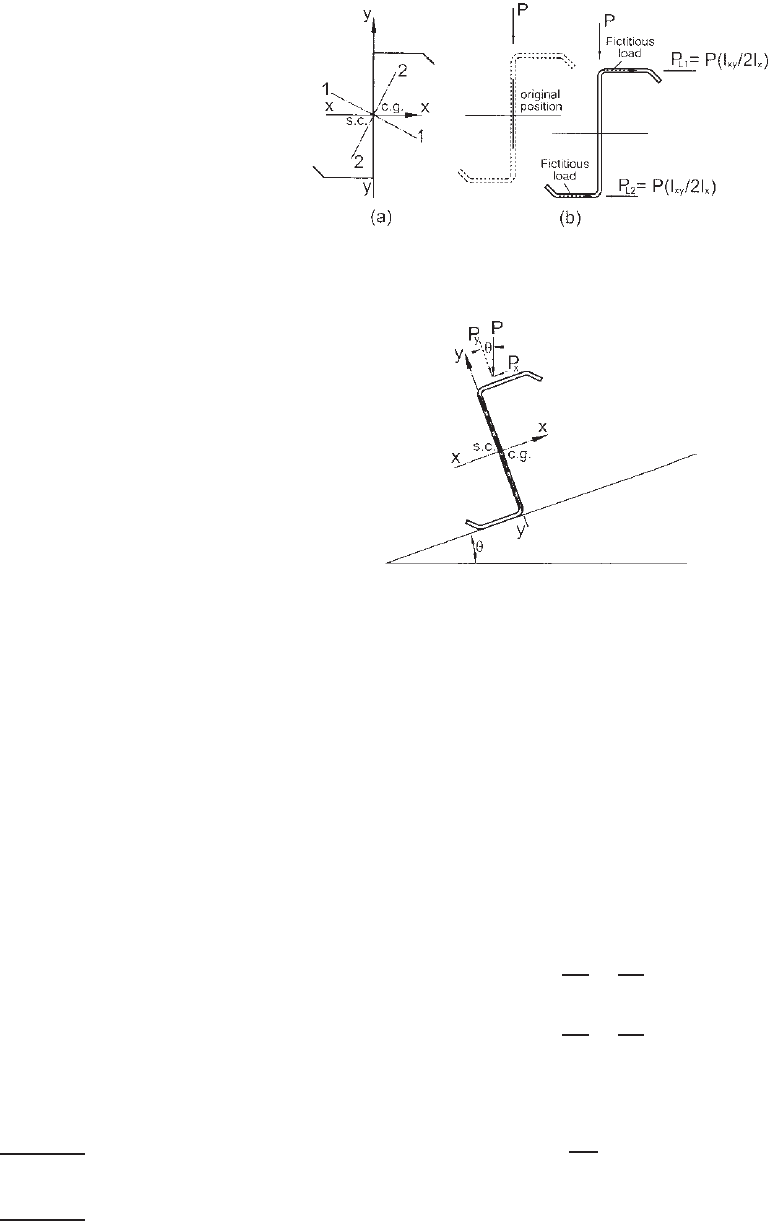
4.4.2 Z-Beams
4.4.2.1 N either Flange Connected to Sheathing For Z-
beams, when a load is applied in the midplane of the web,
the section does not tend to rotate in the same manner
as channels because the shear center coincides with its
centroid, as shown in Fig. 4.84a. However, in view of
the fact that in Z-sections the principal axes are oblique,
even though such a section is loaded vertically, it will
deflect vertically and horizontally, as shown in Fig. 4.84b.
When the section deflects in the horizontal direction, the
applied load will also move with the beam and is no longer
in the same plane with the reactions at both ends. As a
result, the section also twists in addition to vertical and
horizontal deflections. The additional stress caused by the
twist reduces the load-carrying capacity of the member.
(a) Bracing of Z-Beams. The investigation carried out by
Zetlin and Winter to study the bracing requirement for
Z-beams consisted of testing 19 beams of three different
shapes.
4.109
An approximate method of analysis indicated
that the braced Z-beams can be analyzed in the same way
as braced channels, except that the total fictitious horizontal
load caused by the actual vertical load should be determined
by P(I
xy
/I
x
). In order to prevent the movement of the Z-
beam along the axis perpendicular to the web, the resistance
brace forces P(I
xy
/2I
x
) should be applied to the top and
bottom flanges (Fig. 4.84b). A term K
is used for the
value of I
xy
/(2I
x
) in Section D3.2.1 of the North American
Specification for Z-beams.
For simplification of design, the vertical and horizontal
deflections and the corresponding stresses can be deter-
mined by the summations of the values computed for the
actual and fictitious loads by using the following modified
moments of inertia (I
mx
and I
my
)
4.109
:
I
mx
=
I
x
I
y
− I
2
xy
I
y
(4.189)
I
my
=
I
x
I
y
− I
2
xy
I
x
(4.190)
Figure 4.84 Z- section subjected to a vertical load through plane
of the web.
Figure 4.85 Z- section subjected to an inclined load on sloped
roof.
(b) Effect of Slope and Eccentricty. When the Z-section
member is used for sloped roofs, the top flange is subject to
an inclinated load as shown in Fig. 4.85. The applied load
can be either a gravity load or an uplift load acting at any
location on the top flange. For this case, both components
P
x
and P
y
should be c onsidered for design.
(c) North American Design Criteria. For Z-beams, a
general method is also provided in Section D3.2.1 of
the North American specification for determining the
resistance brace forces P
L1
and P
L2
as follows:
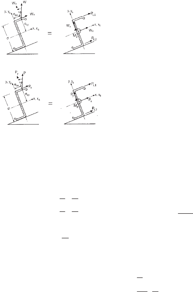
1. For uniform loads (Fig. 4.86)
P
L1
= 1.5
W
y
K
−
W
x
2
+
M
z
d
(4.191)
P
L2
= 1.5
W
y
K
−
W
x
2
−
M
z
d
(4.192)
When the uniform load W acts through the midplane of
the web, that is, W
y
= W and W
x
= 0,
P
L1
= P
L2
= 1.5
I
xy
2I
x
W (4.193)
where K
= I
xy
/(2I
x
)
I
xy
= product of inertia of full unreduced section
BRACING REQUIREMENTS OF BEAMS 189
Figure 4.86 Z- section member subjected to a uniform load.
Figure 4.87 Z-section member dubjected to a concentrated
load.
1.346
I
x
= moment of inertia of full unreduced
section a bout x axis
and W , W
x
, W
y
, d , M
z
, e
sx
and e
sy
were defined in
Section 4.4.1.1. The justification for using a factor of
1.5 in Eqs. (4.191)–(4.193) was discussed in Section
4.4.1.1.
2. For c oncentrated loads (Fig. 4.87),
P
L1
= P
y
K
−
P
x
2
+
M
z
d
(4.194)
P
L2
= P
y
K
−
P
x
2
−
M
z
d
(4.195)
When a design load (factored load) acts through the
plane of the web, that is, P
y
= P and P
x
= 0,
P
L1
= P
L2
=
I
xy
2I
x
P (4.196)
In Eqs. (4.194), (4.195), and (4.196), K
, I
x
,andI
xy
are
defined under item 1 above; P
x
, P
y
, P, d ,andM
z
were
defined in Section 4.4.1.1.
The general provisions of Section 4.4.1.1 for C-
section members are equally applicable to Z-section
members. The commentary on the 2007 edition of
the North American specification also provides the
design equations for Z-section member rests on a sloped
roof.
1.346
4.4.2.2 Top Flange Connected to Sheathing When Z-
sections are used for roof construction to support the
attached sheathing directly, the 1986 AISI Specification
through the 2007 North American Specification included
brace force equations that were based on the work by
Murray and Elhouar,
4.110
Lee and Murray,
4.274
Seek and
Murray,
4.275,4.276,4.277
and Sears and Murray.
4.278
For the
current design requirements, see Section 9.5.
4.4.3 I-Beams
For I-beams, braces should be attached to top and bottom
flanges at both ends. According to Section 4.2.3.3, if F
e
is
greater than or equal to 2.78F
y
and S
c
= S
f
, no intermediate
braces are required, except that additional braces should be
placed at the locations of concentrated loads.
In case the value of F
e
is less than 2.78F
y
but greater
than 0.56F
y
, the intervals of braces should not exceed the
required unbraced length determined from Eqs. (4.63) and
(4.64a). If F
e
is less than or equal to 0.56F
y
, the required
unbraced length s hould be determined from Eqs. (4.63) and
(4.64b).
The design of braces is not specified in the Specification
at the present time (2009). However, the bracing members
may be designed for a capacity of 2% of the force resisted
by the compression portion of the beam. This is a frequently
used rule of thumb but is a conservative approach, as proven
by a rigorous analysis.
4.4.4 Continuous Lateral Bracing for Beams
When the compression flange of the cold-formed steel
beam is closely connected to decking or sheathing material
as to effectively restrain lateral deflection of the flange
and twisting of the member, previous studies made by
Winter
1.157,4.111
indicated that the required resistance to be
provided by decking may be approximated as follows:
F
req
= d
i
β
id
β
id
/β
act
(4.197)
where F
req
= required lateral force provided by decking
d
i
= initial crookedness
β
act
= extensional stiffness of decking material,
=AE /L
,inwhichA is area of decking, E is
modulus of elasticity, and L
is length
and β
id
, the spring constant of elastic support, is computed
as follows:
β
id
=
⎧
⎪
⎪
⎪
⎨
⎪
⎪
⎪
⎩
π
2
L
2
(P
cr
− P
e
) when β
id
L
2
≤ 30P
e
(4.198)
π
2
P
e
4L
2
P
cr
P
e
− 0.6
2
when β
ib
L
2
> 30P
e
(4.199)
190 4 FLEXURAL MEMBERS
where L = length of beam
P
e
= Euler critical load, = π
2
EI
yc
/L
2
P
cr
= critical load for c ompressed half of beam
buckling out of its plane as a column
I
yc
= moment of inertia of compressed portion of
beam about its weak axis
During the past four decades, the strength and behavior
of diaphragm-braced beams loaded in the plane of the web
have been studied by numerous investigators at Cornell
University and several other institutions. The published
research reports and technical papers provide a better under-
standing of such a complicated problem.
4.110–4.136,4.274–4.278
These documents contain valuable background information
for developing new design recommendations for channels
and Z-sections when one flange is connected to deck or
sheathing material.
4.5 TORSIONAL ANALYSIS OF BEAMS AND
COMBINED BENDING AND TORSIONAL
LOADING
4.5.1 Torsional Analysis of Beams
In the design of beams, if the transverse load does not
pass through the shear center of the cross section, the
beam is subject to a combination of plane bending and
torsional moment.
2.45,4.140
The types of stress caused by
plane bending and torsion are discussed in Appendix B.
4.5.2 Combined Bending and Torsional Loading
When a beam is subject to a combination of bending
and torsion, the longitudinal and shear stresses caused by
plane bending and torsion are discussed in Appendix B.
The calculations of these types of stress are illustrated in
Example B1 of Appendix B.
For the design of such a beam subjected to combined
bending and torsion, the nominal flexural strength, M
x
,
calculated from Section 4.2.2.1 for bending alone should
be reduced to take into account the effect of torsion. A new
Section C3.6 was added in the 2007 edition of the North
American Specification for combined bending and torsional
loading.
1.345,1.346
For detailed discussion, see Section B4 of
Appendix B.
In addition to the reduction of the nominal flexural
strength for combined bending and torsion, the reduction of
nominal shear strength can be handled in a similar manner
on the basis of the shear stresses caused by plane bending
and torsion. The calculations of different shear stresses are
also discussed in Appendix B.
4.6 ADDITIONAL INFORMATION ON BEAMS
During the past three decades, the structural strength of
cold-formed steel purlins has been investigated by a large
number of researchers and engineers. For further infor-
mation on this subject, the reader is referred to Refs.
4.137–4.139, 4.141–4.155, 4.187–4.191,1.414, 2.103, and
4.279–4.292.
CHAPTER 5
Compression Members
5.1 GENERAL REMARKS
Similar to the heavy hot-rolled s teel sections, thin-walled
cold-formed steel compression members can be used to
carry a compressive load applied through the centroid of
the cross section. The cross section of steel columns can
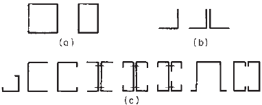
be of any shape that may be composed entirely of stiff-
ened elements (Fig. 5.1a), unstiffened elements (Fig. 5.1b),
or a combination of stiffened and unstiffened elements
(Fig. 5.1c). Unusual shapes and closed cylindrical tubular
sections are also often found in use.
Cold-formed sections are made of thin material, and in
many cases the shear center does not coincide with the
centroid of the section. Therefore in the design of such
compression members, consideration should be given to the
following limit states depending on the configuration of the
section, thickness of material, and column length used:
1. Yielding
2. Overall column buckling
a. Flexural buckling: bending about a principal axis
b. Torsional buckling: twisting about shear center
c. Flexural–torsional buckling: bending and twisting
simultaneously
3. Local buckling of individual compression elements
4. Distortional buckling of open sections with edge-
stiffened flanges
Design provisions for the overall flexural buckling and
the effect of local buckling on column strength have long
been included in the AISI Specification. The provisions
for flexural–torsional buckling were added to the speci-
fication in 1968 following a comprehensive investigation
carried out by Winter, Chajes, Fang, and Pekoz at Cornell
University.
1.161,5.1,5.2
Figure 5.1 Types of compression members: (a)members
composed entirely of stiffened elements; (b) members composed
entirely of unstiffened elements; (c) members composed of both
stiffened and unstiffened elements.
The design provisions have been based on the unified
approach developed in 1986 and discussed by Pekoz in
Ref. 3.17. This approach consists of the following steps for
the design of axially loaded compression members:
1. Calculate the elastic column buckling stress (flexural,
torsional, or flexural–torsional) for the full unreduced
section.
2. Determine the nominal failure stress (elastic buckling,
inelastic buckling, or yielding).
3. Calculate the nominal column load based on the
governing failure stress and the effective area.
4. Determine the design column load from the nominal
column load using the specified safety factor or the
resistance factor.
In 2007, the design provisions for determining the distor-
tional buckling strength of I-, Z-, C-, hat, and other open
sections having edge-stiffened flanges were added in the
North American Specification.
1.345
For column design tables and example problems, refer-
ences should be made to Part III of the 2008 edition of the
AISI Design Manual.
1.349
The column strengths for different failure modes are
discussed in s ubsequent sections of this chapter. References
5.3–5.8, 5.100, 5.110, 5.114, 5.126, 5.133, and 5.141–5.155
deal with some previous and recent studies on columns.
5.2 YIELDING
It is well known that a very short, compact column under
axial load may fail by yielding. For this case, the yield load
is simply
P
y
= AF
y
(5.1)
where A = full cross-sectional area of column
F
y
= yield stress of steel
191
192 5 COMPRESSION MEMBERS
5.3 FLEXURAL COLUMN BUCKLING
5.3.1 Elastic Buckling
A slender a xially loaded column may fail by overall flex-
ural buckling if the cross section of the column is a doubly
symmetric shape (I-section), closed shape (square or rect-
angular tube), closed cylindrical shape, or point-symmetric
shape (Z-shape or cruciform). For s ingly symmetric shapes,
flexural buckling is one of the possible failure modes, as
discussed in Section 5.4.2. If a column has a cross s ection
other than the above-discussed shapes but is connected to
other parts of the structure such as wall sheating material,
the member can also fail by flexural buckling. For other
possible buckling modes, see Section 5.4.
The elastic critical buckling load for a long column can
be determined by the Euler formula:
P
e
=
π
2
EI
(KL)
2
(5.2)
where P
e
= Euler buckling load
E = modulus of elasticity
I = moment of inertia
L = column length
K = effective length factor
Substituting I = Ar
2
in Eq. (5.2) or dividing Eq. (5.2) by
the full a rea A, the following Euler stress for elastic column
buckling can be obtained:
σ
e
=
π
2
E
(KL/r)
2
(5.3)
where KL/r is the effective slenderness ratio and r is the
least radius of gyration.
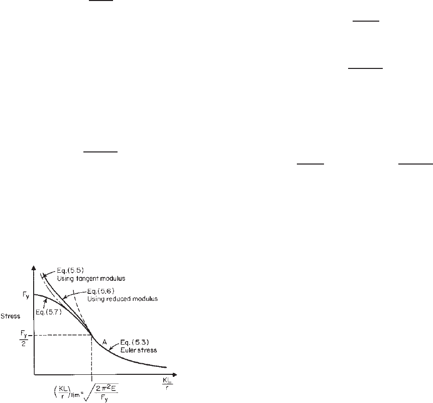
Equation (5.3) is graphically shown as curve A in
Fig. 5.2, which is applicable to the ideal columns made
of sharp-yielding-type steel having stress–strain character-
istics as shown in Fig. 2.1a without consideration of residual
Figure 5.2 Flexural column buckling stress.
stress or effects of cold working. In view of the fact that
many steel sheets and strips used for cold-formed struc-
tural members are of the gradual-yielding type as shown
in Fig. 2.1b and the cold-forming process tends to lower
the proportional limit as discussed in Section 2.7, Eq. (5.3)
would not be suitable for columns made of gradual-yielding
steel having small and moderate slenderness ratios. This is
because when the s tress is above the proportional limit, the
column will buckle in the inelastic range.
5.3.2 Inelastic Buckling
For the flexural column buckling in the inelastic range, two
concepts have been used in the past. They are the tangent
modulus method and the reduced-modulus method.
2.45,3.3
The tangent modulus method was proposed by Engesser
in 1889. Based on this method, the tangent modulus
load is
P
T
=
π
2
E
t
I
(KL)
2
(5.4)
and the critical buckling stress is
σ
T
=
π
2
E
t
(KL/r)
2
(5.5)
where E
t
is the tangent modulus.
In 1895 Jasinky pointed out that the tangent modulus
concept did not include the effect of elastic unloading.
Engesser then corrected his theory and developed the
reduced- or double-modulus concept, in which
P
r
=
π
2
E
r
I
(KL)
2
or σ
R
=
π
2
E
r
(KL/r)
2
(5.6)
where E
r
= reduced modulus, E(I
1
/I ) + E
t
(I
2
/I )
I
1
= moment of inertia about neutral axis of the
area on unloading side after buckling
1
2
= moment of inertia about neutral axis of the
area on loading side after buckling
Engineers were puzzled for about 50 years regarding
these two concepts for the determination of column
strength. After his careful experimental and analytical
investigation, Shanley
5.9
concluded that:
1. The tangent-modulus concept gives the maximum
load up to which an initially straight column remains
straight.
2. The actual maximum load exceeds the tangent
modulus load, but it cannot reach the reduced-
modulus load.
Many other investigators have proved Shanley’s findings
and have indicated that for the case studied the maximum
FLEXURAL COLUMN BUCKLING 193
load is usually higher than the tangent modulus load by 5%
or less.
2.45
In view of the fact that the tangent modulus strength
provides an excellent prediction of the actual column
strength, the Column Research Council
∗
has suggested that
design formulas for steel columns should be on the basis
of the tangent modulus concept.
3.84
For this reason, when-
ever the computed Euler stress is above the proportional
limit, the tangent modulus should be used to compute the
buckling stress.
The tangent modulus can be determined by the tech-
niques described in Technical Memorandum 2 of the
Structural Stability Research Council, “Notes on the
Compression Testing of Metals,”
3.84,1.158,1.412
However, it
is impossible to provide stress–strain curves and values
of tangent moduli for all types of sheets and strip, in
particular when the c old work of forming is utilized. In
the design of hot-rolled shapes, the Structural Stability
Research Council has indicated that Eq. (5.5) can be
conservatively approximated by the following formula if
the effect of residual stress is considered and the effective
proportional limit is assumed to be equal to one-half the
yield stress
1.161,3.84
:
σ
T
= F
y
1 −
F
y
4σ
e
= F
y
−
F
2
y
4π
2
E
KL
r
2
(5.7)
in which F
y
is the minimum yield stress. The above formula
can also be used for cold-formed sections if the residual
stress induced by cold forming of the section and the
stress–strain characteristics of the gradual-yielding steel
sheets and strip are considered.
As shown in Fig. 5.2, the value of
2π
2
E/F
y
is the
limiting KL/r ratio corresponding to a stress equal to F
y
/2.
When the KL/r ratio is greater than this limiting ratio, the
column is assumed to be governed by elastic buckling, and
when the KL/r ratio is smaller than this limiting ratio, the
column is to be governed by inelastic buckling. Equation
(5.7) has been used for the design of cold-formed steel
columns up to 1996.
In the 1996 edition of the AISI Specification, the design
equations for calculating the nominal inelastic and elastic
flexural buckling stresses were changed to those used in the
AISC LRFD Specification as follows
3.150
:
(
F
n
)
I
=
0.658
λ
2
c
F
y
when λ
c
≤ 1.5 (5.7a)
(
F
n
)
e
=
0.877
λ
2
c
F
y
when λ
c
> 1.5 (5.3a)
∗
The Column Research Council has been renamed Structural Stability
Research Council.
where (F
n
)
I
is the nominal inelastic buckling stress, (F
n
)
e
is the nominal elastic buckling stress, λ
c
=
F
y
/σ
e
is
the column slenderness parameter, in which σ
e
is the
theoretical elastic flexural buckling stress of the column
determined by Eq. (5.3).
The reasons for changing the design e quations from Eq.
(5.7) to Eq. (5.7a) for the nominal inelastic buckling stress
and from Eq. (5.3) to Eq. (5.3a) for the nominal elastic
buckling stress are as follows:
1.159
1. The revised column design equations [Eqs. (5.7a)
and (5.3a)] are based on a different basic s trength
model and were shown to be more accurate by
Pekoz and Sumer.
5.103
In this study, 299 test results
on columns and beam–columns were evaluated. The
test specimens included members with component
elements in the post–local buckling range as well
as those that were locally stable. The test specimens
included members subjected to flexural buckling as
well as flexural–torsional buckling, to be discussed in
Section 5.4.
2. Because the revised column design equations repre-
sent the maximum strength with due consideration
given to initial crookedness and can provide the better
fit to test results, the required s afety factor for the
ASD method can be reduced. In addition, the revised
equations enable the use of a single safety factor for
all λ
c
values even though the nominal axial strength of
columns decreases as the slenderness increases due to
initial out-of-straightness. With the use of the selected
safety factor and resistance factor given in the spec-
ification (Section 5.8), the results obtained from the
ASD and LRFD approaches would be approximately
the same for a live load–dead load ratio of 5.0.
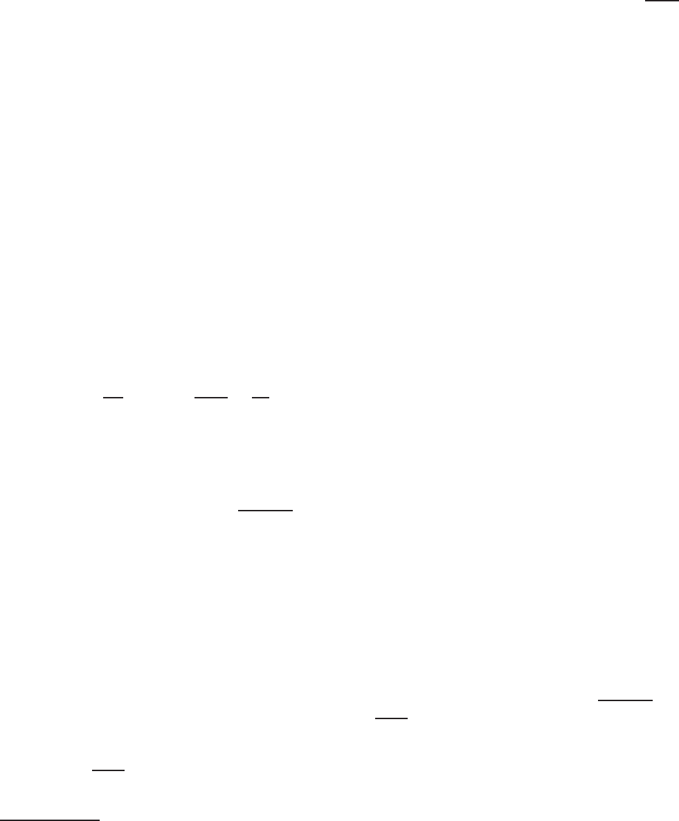
Figure 5.3 shows a comparison of the nominal critical
flexural buckling stresses used in the 1986 edition of the
ASD specification, the 1991 edition of the LRFD Specifi-
cation, and the 1996 edition of the combined ASD/LRFD
Specification. The North American specification uses the
same equations as the 1996 AISI Specification.
It should be noted that by using Eqs. (5.7a) and (5.3a)
the limiting KL/r ratio is changed from
2π
2
E/F
y
to 4.71
E/F
y
corresponding to an assumed proportional limit of
0.44F
y
. This revised limiting KL/r ratio is being used in
the 2005 edition of the AISC Specification for the design
of structural steel members for compression.
1.411
For cold-
formed steel design, Eqs. (5.7a) and (5.3a) are retained in
the 2007 edition of the North American Specification for
the design of concentrically loaded compression members.
For details, see Section 5.8.
194 5 COMPRESSION MEMBERS
Figure 5.3 Comparison between the critical buckling stress equations.
5.4 TORSIONAL BUCKLING AND
FLEXURAL–TORSIONAL BUCKLING
Usually, closed sections will not buckle torsionally because
of their large torsional rigidity. For open thin-walled
sections, however, three modes of failure are consid-
ered in the analysis of overall instability (flexural buck-
ling, torsional buckling, and flexural–torsional buckling) as
previously mentioned.
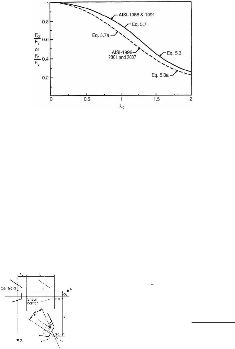
When an open-section column buckles in the flexural–
torsional mode, bending and twisting of the section occur
simultaneously. As shown in Fig. 5.4, the section translates
u and v in the x and y directions and rotates an angle
φ about the shear center. This problem was previously
investigated by Goodier, Timoshenko, and others.
5.10,5.11,3.3
It has been further s tudied by Winter, Chajes, and Fang for
development of the AISI design criteria.
5.1,5.2
Figure 5.4 Displacement of a nonysmmetric section during
torsional–flexural buckling.
5.2
The equilibrium of a column subjected to an axial load
P leads to the following differential equations
5.2,5.11
:
EI
x
v
iv
+ Pv
− Px
0
φ
= 0 (5.8)
EI
y
u
iv
+ Pu
+ Py
0
φ
= 0 (5.9)
EC
W
φ
iv
− (GJ − Pr
2
0
)φ
+ Py
0
u
− Px
0
v
= 0 (5.10)
where I
x
= moment of inertia about x axis
I
y
= moment of inertia about y axis
u = lateral displacement in x direction,
v = lateral displacement in y direction
φ = angle of rotation
x
0
= x coordinate of shear center
y
0
= y coordinate of shear center
E = modulus of elasticity, = 29.5 × 10
3
ksi
(203 GPa, or 2.07 × 10
6
kg/cm
2
)
G = shear modulus, = 11.3 × 10
3
ksi (78 GPa, or
794×10
3
kg/cm
2
)
J = St. Venant torsion constant of cross section,
1
3
l
i
t
3
i
C
w
= warping constant of torsion of cross section
(Appendix B)
EC
w
= warping rigidity
GJ = torsional rigidity
r
0
= polar radius of gyration of c ross section about
shear center, =
r
2
x
+ r
2
y
+ x
2
0
+ y
2
0
r
y
,r
y
= radius of gyration of cross section about x
and y axes
All derivatives are with respect to z, the direction along
the axis of the member.