Chen C.J. Physics of Solar Energy
Подождите немного. Документ загружается.

i
i
“ChenSolarEnergy” — 2011/5/17 — 17:56 — page 213 — #240
i
i
i
i
i
i
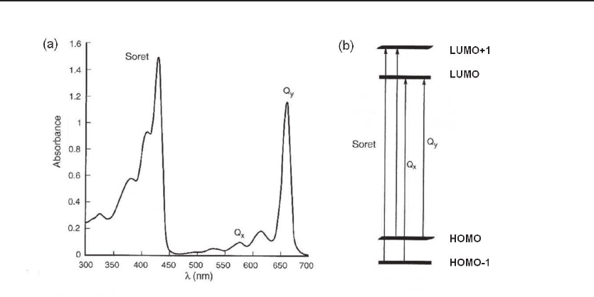
Figure 10.2 Absorption spectra of chlorophyll a. (a) The absorption peaks of chlorophyll a are
in the red, yellow, and blue through the near-ultraviolet ranges. It is transparent to green light, which
gives its characteristic green color. (b) Energy-level diagram of chlorophyll. The absorption peak in
the red near 660 nm corresponds to the transition from the HOMO to the LUMO. The absorption peak
in the yellow, around 570 nm, corresponds to the transition from one level below the HOMO to the
LUMO. The peak in the violet, near 430 nm, corresponds to the transition from energy levels below
the HOMO to energy levels above the LUMO. In a very short period of time, all those excitations are
relaxed to the molecular state with one LUMO, which is about 1.88 eV above the ground state.
and C
2
H
5
are bonded. Many other types of chlorophylls share the basic structure but
with different groups at the external positions.
The absorption spectrum of chlorophyll a and its interpretation are shown in Fig. 10.2.
It has three major groups of absorption peaks, centered at 662 nm (red), 578 nm (yel-
low), and 430 nm (blue). The green region is transparent, which gives rise to its char-
acteristic green color. The energy diagram of chlorophyll a is shown in Fig. 10.2(b). In
addition to the highest occupied molecular orbital (HOMO) and the lowest unoccupied
molecular orbital (LUMO), two additional energy levels, one below the HOMO and one
above the LUMO, are required to explain the absorption spectrum in the visible region.
The absorption peak in the red, near 660 nm, corresponds to the transition from the
HOMO to the LUMO. The absorption peak in yellow, around 570 nm, corresponds to
the transition from one level below the HOMO to the LUMO. The peak in the violet,
near 430 nm, corresponds to the transition from energy levels below the HOMO to
energy levels above the LUMO. In a very short period of time, all those excitations
are relaxed to the molecular state with one LUMO, which is about 1.88 eV above the
ground state.
The energy stored in the excited chlorophyll molecule is transferred to an energy
storage molecule, adenosine triphosphate (ATP). Then, ATP drives the process to
synthesize sugar from carbon dioxide and water.
10.1 Physics of Photosynthesis 213
i
i
“ChenSolarEnergy” — 2011/5/17 — 17:56 — page 214 — #241
i
i
i
i
i
i
214 Solar Electrochemistry
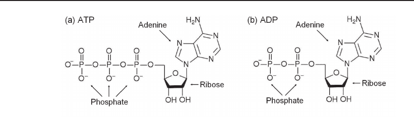
Figure 10.3 ATP and ADP. Both molecules contain an adenine, a ribose, and two or three
phosphate groups. It takes energy to attach a phosphate group to ADP to form ATP. By detaching
a phosphate group from ATP to recover ADP, energy is released. ATP is the universal “rechargeable
battery” in biological systems.
10.1.2 ATP: Universal Energy Currency of Life
The structures of ATP and a related molecule adenosine diphosphate (ADP) are shown
in Fig. 10.3. Both contain a nitrogenous base called adenine, a five-carbon sugar
called ribose, and two or three phosphate groups. (Adenine is also one of the four
nitrogenous bases which are the building blocks of DNA, the genetic code material.)
These molecules are the universal rechargeable batteries in biological systems. ATP is
the charged battery and ADP is the discharged battery. It takes some energy to attach
a phosphate group to ADP to form ATP. By detaching a phosphate group from ATP
to recover ADP, energy is released:
ATP
4−
+H
2
O −→ ADP
3−
+HPO
2−
4
+H
+
+0.539 eV. (10.3)
The molecules ADP and ATP were isolated in 1929 from muscle tissues. In 1940,
Fritz Lipmann (who won the Nobel Prize for Physiology and Medicine, 1953) proposed
that ATP is the universal energy currency in cells. For example, when a human being
is doing an aerobic exercise, glucose is oxidized by the oxygen in the blood into carbon
dioxide and water, at the same time releasing energy. The energy is temporarily stored
as ATP. Then the energized ATP drives the contraction of muscles.
The central role of ATP in photosynthesis was proposed by Daniel Arnon in the
1950s. His idea was met with a lot of skepticism. Then, a colleague in the same
university, Berkeley, Melvin Calvin, did a series of experiments and discovered the
process of photosynthesis and verified Arnon’s hypothesis.
The molecule ATP plays such an important role in the energetics of life that further
elucidation of its synthesis mechanism resulted in the 1997 Nobel Prize in Chemistry
for Paul D. Boyer and John E. Walker and was named “The Molecule of the Year” by
Science magazine in 1998.
10.1.3 NADPH and NADP
+
Besides transferring energy, reduction of CO
2
into carbon hydride is also required in
the synthesis of glucose. The reduction agent in this process is NADPH, which can
i
i
“ChenSolarEnergy” — 2011/5/17 — 17:56 — page 215 — #242
i
i
i
i
i
i
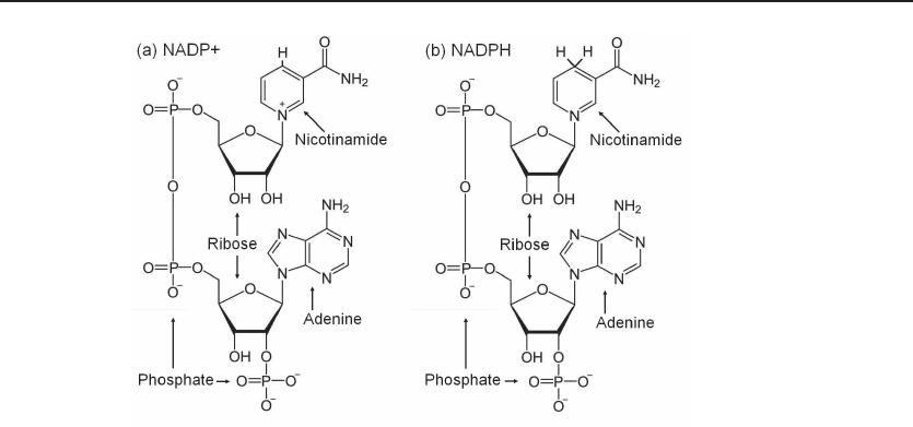
Figure 10.4 NADPH and NADP
+
. The reduction agent in living systems. Both molecules contain
a nicotinamide group, an adenine group, two ribose groups, and three phosphate groups. NADPH has
two hydrogen atoms at a site on the nicotinamide. During reduction, it releases a hydrogen atom with
an electron and becomes NADP
+
.
release a hydrogen atom with an electron and become NADP
+
. Both molecules contain
a nicotinamide group, an adenine group, two ribose groups, and three phosphate groups
(Fig. 10.4).
10.1.4 Calvin Cycle
During 1940s and 1950s, Melvin Calvin and his colleagues performed a series of ex-
periments using a carbon isotope and worked out the pathway of photosynthesis. By
adding
14
CO
2
to a liquid containing the green alga Chlorella pyrenoidosa, using two-
dimensional paper chromatograms, the subsequent molecules of the photosynthesis pro-
cess were traced by the radioactivity of the
14
C atoms. The details of the process, the
Calvin cycle, is rather complicated. Interested readers are recommended to check the
books of Blankenship [11] or Chapter 24 of Voet [86]. Here we highlight some key
points of the Calvin cycle with respect to energy transfer processes.
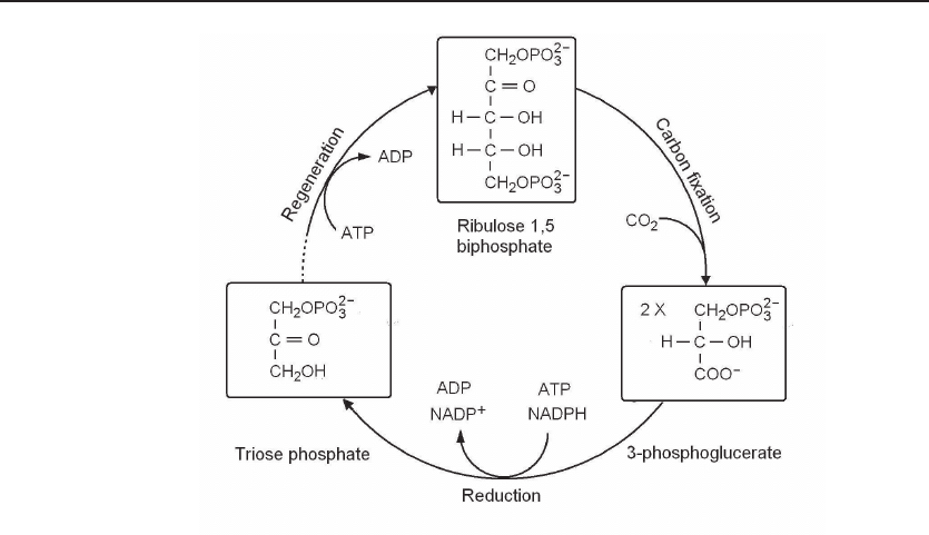
Figure 10.5 shows key steps in the Calvin cycle. The most significant discovery
of Calvin’s experiments is that the assimilation of carbon from CO
2
results in the
generation of two identical three-carbon molecules (3-phosphoglycerate) by inserting a
carbon atom and then cracking a five-carbon molecule (ribulose-1,5-biphosphate). The
first step of the Calvin cycle is called carbon fixation. The next step is to reduce the
carboxyl group to form triose phosphate by NADPH. The entire process of generating
glucose requires that carbon fixation be repeated six times. In each loop, the five-
carbon molecule (ribulose-1,5-biphosphate) must be regenerated to prepare for the next
carbon assimilation process. It takes 9 – 10 photons to complete the process of fixing
each carbon atom into the final product, for example, glucose.
10.1 Physics of Photosynthesis 215
i
i
“ChenSolarEnergy” — 2011/5/17 — 17:56 — page 216 — #243
i
i
i
i
i
i
216 Solar Electrochemistry
Figure 10.5 Key steps in the Calvin cycle. The Calvin cycle has three major steps. The
first step, carbon fixation, is the insertion of a CO
2
molecule into a molecule with five carbon atoms
and two phosphate groups. The resulting molecule is split, generating two identical molecules with
three carbon atoms each. In a subsequent step, the molecule is reduced by the action of NADPH.
The process repeats six times to generate a glucose molecule. In each loop, the five-carbon molecule
(ribulose-1,5-biphosphate) must be regenerated to prepare for the next carbon fixation step.
10.1.5 C4 Plants versus C3 Plants
In the conventional Calvin cycle, there is an alternative reaction in the carbon fixation
step: An oxygen molecule can take the role of the CO
2
and generate two different
products, one with three carbon atoms and another with two carbon atoms. The
process using oxygen, photoperspiration, reduces the efficiency.
In some plants, such as maize (corn) and sugarcane, a better process takes place
in the carbon fixation step to circumvent photorespiration by a CO
2
pumping mech-
anism which generates two identical molecular fragments of four carbon atoms each.
Because the initial products of carbon fixation is a 4-carbon-atom molecule instead of a
three-carbon-atom molecule, such variation of the Calvin cycle is called a C4 cycle and
plants such as maize and sugarcane are called C4 plants. Especially under high tem-
perature and high insolation environments, the photosynthesis efficiency of C4 plants
is significantly higher than the great majority of plants which have a C3 cycle [11].
10.1.6 Chloroplast
In plants, photosynthesis actions and ingredients are contained in disklike units called
chloroplasts, see Fig. 10.6(a). The chloroplast, with a typical size of 5 μm, has a well-
i
i
“ChenSolarEnergy” — 2011/5/17 — 17:56 — page 217 — #244
i
i
i
i
i
i
10.1 Physics of Photosynthesis 217
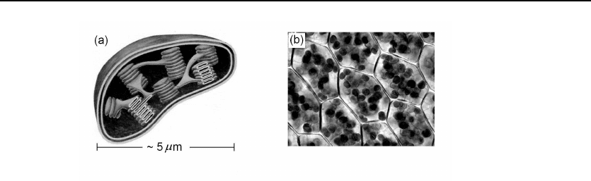
Figure 10.6 Chloroplast. (a) Chloroplast is the site of photosynthesis in plants. With a typical
size of 5 µm, it has a well-defined structure to facilitate the flow of water, CO
2
, and products. (b) A
typical leaf cell contains 20 – 60 chloroplasts.
defined structure to facilitate the flow of water, CO
2
, and products. Typically, each
leaf cell contains 20 – 60 chloroplasts; see Fig. 10.6(b). A 1-mm
2
section in a typical
corn leaf can have as many as a half million chloroplasts.
10.1.7 Efficiency of Photosynthesis
From an engineering point of view, the efficiency of photosynthesis is a critical pa-
rameter. By efficiency we mean the ratio of the chemical energy of the products of
photosynthesis and the solar energy falling on the leaves.
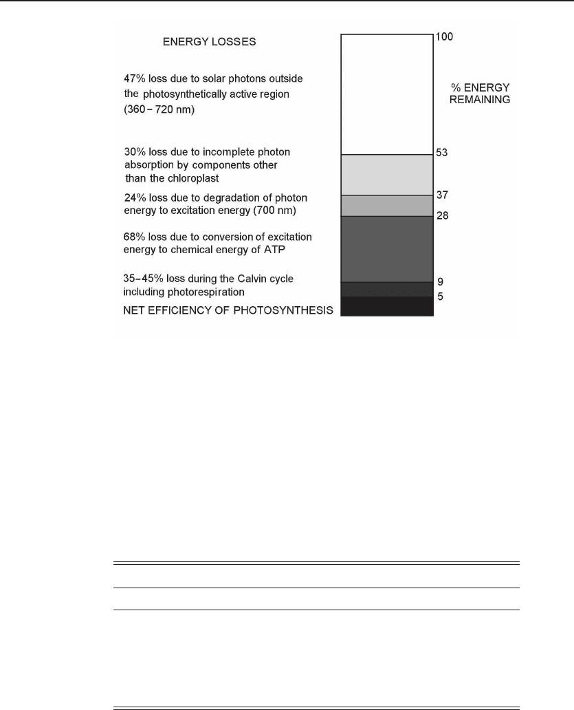
Figure 10.7 shows the results of a study by Bolton and Hall [12]. The first loss is
due to the wavelength range. The chlorophyll only absorbs less than one-half of the
solar radiation, which is red, orange, and blue. The rest has no effect. The second
loss is relaxation. As shown in Fig. 10.2, the excited molecule quickly relaxes to the
state with only one LUMO, which is about 1.8 eV. The energy in the excited state of
chlorophyll must be temporarily stored as usable chemical energy, the energy in ATP
and NADPH, which is about 0.54 eV for each molecule. Sixty-eight percent of the
energy is lost. The Calvin cycle is also not 100% efficient:. 35 – 45% of energy is lost.
As a result, the net efficiency is about 5%.
Although the numerical value of the efficiency looks miserable, because of the enor-
mous area of ground covered by plants, the total production of chemical energy by
photosynthesis over the world each year is 3×10
21
J, which is 6 times the total global
consumption of energy in 2008.
To compare photosynthesis with other solar energy utilization processes, one often-
used measure is power density in watts per square meter, defined as the chemical energy
produced each year on a square meter of land divided by the number of seconds in a
year. Note that the final useful product, for example, sugar or biodiesel, is only a small
part of the total chemical product of photosynthesis. A large part of the products of
photosynthesis, such as roots, branches, and leaves, is not useful. Table 10.1 is based on
the data provided by a report published by United Nations Development Programme
[72]. For comparison, data on total solar radiation and the power density of typical
i
i
“ChenSolarEnergy” — 2011/5/17 — 17:56 — page 218 — #245
i
i
i
i
i
i
218 Solar Electrochemistry
Figure 10.7 Efficiency of photosynthesis. The net efficiency of photosynthesis is about 5%.
Notice that the largest percentage loss is due to the conversion of excitation energy in chlorophyll into
ATP, that is, charging the biological rechargeable battery; and the limited wavelength range of the
absorption spectrum of chlorophyll [12].
solar cells are also included. The average insolation is 1500 h per year. The average
efficiency of crystalline silicon solar cell is 15%. The energy density of biomass is still
much lower than that of typical solar cells. However, the cost of plants is much lower
than solar cells.
Table 10.1: Power Density of Photosynthesis.
Item Energy Density Power Density
Parameter (MJ/year/m
2
)(W/m
2
)
Average solar radiation 5400 171
Average silicon solar cell 810 25.6
Wood (commercial forestry) 3 – 8 0.095 – 0.25
Rapeseed (northwest Europe) 5 – 9 0.16 – 0.29
Sugarcane (Brazil, Zambia) 40 – 50 1.27 – 1.58
Source: World Energy Assessment: Energy and
the Challenge of Sustainability, UNDP 2000 [72].

i
i
“ChenSolarEnergy” — 2011/5/17 — 17:56 — page 219 — #246
i
i
i
i
i
i
10.2 Artificial Photosynthesis 219
10.2 Artificial Photosynthesis
For many decades, scientists have been trying to mimic the elegant process of photo-
synthesis to convert sunlight into fuel which can be stored and applied to, for example,
transportation. The most studied approach is to use sunlight to split water into hy-
drogen and oxygen,
H
2
O+2.46 eV −→ H
2
+
1
2
O
2
. (10.4)
Hydrogen can be used directly as a clean fuel. Once hydrogen is generated, by combin-
ing with carbon dioxide, liquid fuel could be generated. Therefore, if this process can
be demonstrated, it should be a true revolution.
The current status and difficulties of this approach have been summarized in a
review paper [6]. Direct cleavage of water into hydrogen and oxygen by sunlight is still
a lofty dream. One experimentally verified approach to generate hydrogen and oxygen
in significant quantity is to generate electricity using solar cells and then split water
through electrolysis. Because of the high cost and low efficiency, it is not competitive
with other means of energy storage, such as rechargeable batteries (see Chapter 12).
10.3 Genetically Engineered Algae
Although artificial photosynthesis is progressing slowly, an alternative approach using
biotechnology seems extremely promising. The focus is on algae. As a source of bio-
logical fuel, algae have several advantages. First, they live in water and thus do not
occupy arable land or require irrigation. Second, algae can have very high oil content,
up to 50%. Third, the waste disposal problem could be minimal. The yield of oil per
unit area per year for algae could be many times greater than even the most efficient
land-based oil-producing plant, the oil palm. Recently, the use of genetically altered
algae to produce liquid fuel has enjoyed much attention. Through gene modification
combined with directed selection, new species or variations of algae could be created
which will grow faster, contain more fuel, and be easy to harvest. For details, see a
report by U.S. Department of Energy [25].
10.4 Dye-Sensitized Solar Cells
The principles of photosynthesis have inspired the invention of a novel type of solar cell,
the dye-sensitized solar cell [32, 33, 64]. It has several advantages over the common
crystalline silicon solar cell. The cost of materials and processing is greatly reduced
because most of the process is by liquid-phase deposition instead of in a vacuum. In
addition, it can be made on lightweight flexible substrates. To date, nearly 10% overall
conversion efficiency from AM1.5 solar radiation to electrical power is achieved.
The sensitization of semiconductors to light of wavelength longer than that corre-
sponding to the band gap has been used in photography and photo-electrochemistry.
i
i
“ChenSolarEnergy” — 2011/5/17 — 17:56 — page 220 — #247
i
i
i
i
i
i
220 Solar Electrochemistry
The silver halides used in photography have band gaps on the order of 2.7 – 3.2 eV,
and are not sensitive to most of the visible spectrum. Panchromatic films were made
by adding dyes to sensitize silver halides, making them responsive to visible light.
Tne typical structure of a dye-sensitized solar cell is shown in Fig. 10.8. The most
used semiconductor titanium dioxide (TiO
2
), has many advantages for sensitized pho-
tochemistry and photoelectrochemistry: It is a low-cost, widely available, nontoxic and
biocompatible material. As such it is also used in health care products as well as do-
mestic applications such as paint pigmentation. The band gap, 3.05 eV, corresponding
to a wavelength of 400 nm, lies in the near-ultraviolet region, which is too high for the
solar spectrum. A dye is needed to mitigate this problem.
The ideal sensitizer for a single junction photovoltaic cell converting standard global
AM1.5 sunlight to electricity should absorb all light below a threshold wavelength of
about 920 nm. In addition, it must also carry attachment groups such as carboxylate or
phosphonate to firmly graft it to the semiconductor oxide surface. Upon excitation it
should inject electrons into the solid with a quantum yield of nearly unity. The energy
level of the excited state should be well matched to the lower bound of the conduction
band of the oxide to minimize energetic losses during the electron transfer reaction.
Its redox potential should be sufficiently high that it can be regenerated via electron
donation from the redox electrolyte or the hole conductor. Finally, it should be stable
enough to sustain about 20 years of exposure to natural light. Much of the research
in dye chemistry is devoted to the identification and synthesis of dyes matching these
requirements while retaining stability in the photoelectrochemical environment. The
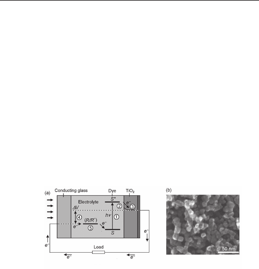
Figure 10.8 Structure of dye-sensitized solar cell. (a) The cell is built on top of a glass substrate
with a conducting film. A nanostructured TiO
2
film of grain size about 15 nm and thickness about
10 μm is deposited on top of that conducting film. Dye molecules with a strong absorption band
in the visible region are deposited on the surface of TiO
2
nanoparticles. The counter electrode is a
film of transparent conducting oxide. The area between the cathode and the anode is filled with an
electrode, typically a solution of lithium iodide. (b) a microscopic image of the TiO
2
film. The process
of generating an electrical power is as follows: (1) Absorption of a photon by the dye to elevate an
electron to the excited state, typically a LUMO. (2) Transfer of the electron to the TiO
2
film. (3) The
electron relaxes to be at the bottom of the conduction band of TiO
2
. (4) A photovoltage is generated
by the cell, corresponding to the difference between the Fermi level in the semiconductor and the
Nernst potential of the redox couple in the electrolyte. Adapted from Refs. [33] and [64].
i
i
“ChenSolarEnergy” — 2011/5/17 — 17:56 — page 221 — #248
i
i
i
i
i
i
10.4 Dye-Sensitized Solar Cells 221
attachment group of the dye ensures that it spontaneously assembles as a molecular
layer upon exposing the oxide film to a dye solution.
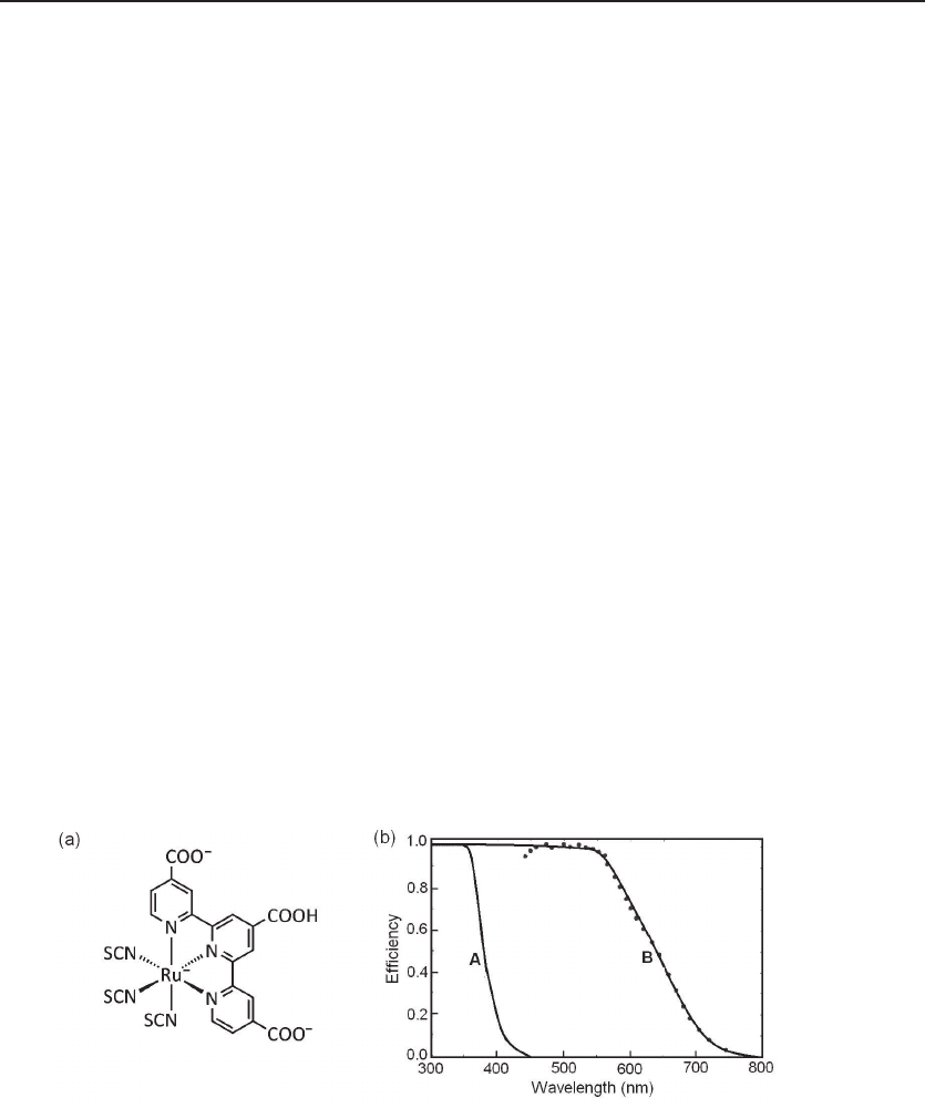
One of the most studied and used dyes is the N3 ruthenium complex shown in
Fig. 10.9. The strong absorption in the visible region makes the dye a deep brown-
black color, thus the name “black dye.” The dyes have an excellent chance of converting
a photon into an electron, originally around 80% but improving to almost perfect con-
version in more recent dyes. The overall efficiency is about 90%, with the “lost” 10%
being largely accounted for by the optical losses in the top electrode. The spectral re-
sponse for a dye-sensitized solar cell using an N3 ruthenium dye is shown in Fig. 10.9(b).
The photocurrent response of a bare TiO
2
film is also shown for comparison.
The four-step process of generating electrical power is as follows (see Fig. 10.8(a)).
1. A photon is absorbed by the dye to elevate an electron to the excited state,
typically a LUMO.
2. The electron is transferred to the TiO
2
film.
3. The electron relaxes to be at the bottom of the conduction band of TiO
2
.
4. A photovoltage is generated by the cell, corresponding to the difference between
the Fermi level in the semiconductor and the Nernst potential of the redox couple
in the electrolyte.
Nevertheless, dye-sensitized solar cells have some disadvantages. First, the efficiency
is about one-half of that of the crystalline silicon solar cells. Second, the necessity of
a liquid-phase electrolyte made the solar cell mechanically weak. Third, the long-term
stability of the organic materials needs to be improved.
Figure 10.9 The N3 ruthenium dye and photocurrent spectrum. (a) Chemical structure
of the N3 ruthenium complex used as a charge transfer sensitizer in dye-sensitized solar cells. (b)
Photocurrent action spectra obtained with the dye as sensitizer, curve B. The photocurrent response
of a bare TiO
2
films, A, is also shown for comparison. Adapted from Refs. [33] and [64].
i
i
“ChenSolarEnergy” — 2011/5/17 — 17:56 — page 222 — #249
i
i
i
i
i
i
222 Solar Electrochemistry
10.5 Bilayer Organic Solar Cells
Another approach to mitigate the high cost of crystalline silicon solar cells is to use
organic semiconductors, or semiconducting polymers, to replace the expensive purified
silicon. Because of its high absorption coefficient in the visible region, a very thin film
of organic material is sufficient. These polymers can be deposited by screen printing,
inkjet printing, and spraying, as these materials are often soluble in a solvent. Fur-
thermore, these deposition techniques can take place at low temperature, which allows
devices to be fabricated on plastic substrates for flexible devices.
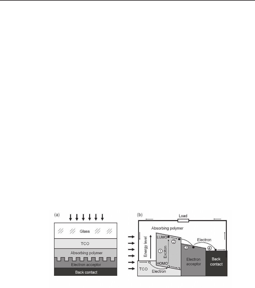
The basic structure of a bilayer organic solar cell is shown in Fig. 10.10(a). There
are two layers of polymer films: a film of an absorbing polymer, the electron donor,and
afilmofelectron acceptor. The double layer is sandwiched between the anode, a TCO
film, and a metal back contact, the cathode. The process of generating a photocurrent
has four steps, see Fig. 10.10(b). In the first step, a photon is absorbed by the polymer,
the electron donor. An exciton, an electron–hole pair, is generated. In the second step,
the exciton diffuses inside the absorbing polymer (the donor) toward the interface to
the acceptor. In the third step, the electron transfers to the acceptor. Finally, the
electron is collected by the cathode, or the back contact. Through the external electric
circuit, the electron goes back to the anode (TCO) and eliminates the hole.
In the first successful bilayer organic solar cell, copper phthaocyanine (CuPc) is
used for the absorbing polymer [80]. The chemical structure and absorption spectrum
are shown in Fig. 10.11. It is a solid with dark blue color, as the red, yellow, green,
and violet radiations are heavily absorbed. The absorption coefficient in some ranges
is more than 10
6
cm
−1
. Therefore, a very thin film of the absorbing polymer, typically
around 100 nm, is used. A larger thickness is conversely a disadvantage because of the
Figure 10.10 Bilayer organic solar cell. (a) A cross sectional view of the solar cell. Solar radiation
comes from the top. Through a glass substrate and a transparent conducting oxide (TCO) film, light is
absorbed by the absorbing polymer film, or the electron donor. The electron thus generated transfers
to the electron acceptor, and then to a metal back contact or the cathode. (b) The working process.
(1). A photon generates an exciton, typically a electron in LUMO and leaves a hole in a HOMO. (2)
The exciton diffuses towards the acceptor. (3) The exciton dissociates into a free electron and a hole.
(4) The electron moves to the cathode, then drives the external circuit. Adapted from Refs. [80, 38].