Chen C.J. Physics of Solar Energy
Подождите немного. Документ загружается.

i
i
“ChenSolarEnergy” — 2011/5/17 — 17:56 — page 233 — #260
i
i
i
i
i
i
11.2 Solar Heat Collectors 233
rugged device which can last for many decades.
The standard treatment of the flat-panel solar heat collectors is based on the Hottel–
Whillier model [39]. Details can be found in Duffie and Beckman [23, 24], Lunde [54],
and other publications [44, 46, 70].
Most solar thermal collectors are covered with glass. The normal-incidence trans-
mittance of the glass cover is (see Chapter 9),
τ =
(4n)
2N
(1 + n)
4N
, (11.8)
where N isthenumberofsheetsandn is the refractive index of glass, typically n =1.5
(see Section 9.4).
Consider a solar collector plate with total area A and absorptivity α.Iftheportion
of effective absorption area is F and the solar power density is P
0
, the input power to
the plate is
Q
I
= FAταP
0
. (11.9)
Because of the solar power, the temperature of the plate is elevated from ambient
temperature T
a
to T
p
. If the temperature difference is not too great, the heat loss is
proportional to the temperature difference. In all practical cases, the area of the panel,
FA, is much greater than the area of the edge. For clarity and brevity, the edge effect
is neglected. The heat loss is also proportional to the area of the hot plate,
Q
L
= U
L
FA(T
p
− T
a
). (11.10)
Here, U
L
is the combined heat loss coefficient. The efficiency of the solar thermal energy
collector is
η =
Q
I
− Q
L
P
0
A
= F
τα−
1
P
0
U
L
(T
p
− T
a
)
+
. (11.11)
The plus sign indicates that only a positive value of the expression is taken. In other
words, if the expression is negative, the value is taken as zero.
Therefore, the problem of the efficiency of the solar heat collector is reduced to
the evaluation of the heat loss coefficient U
L
. For flat-panel collectors, the problem is
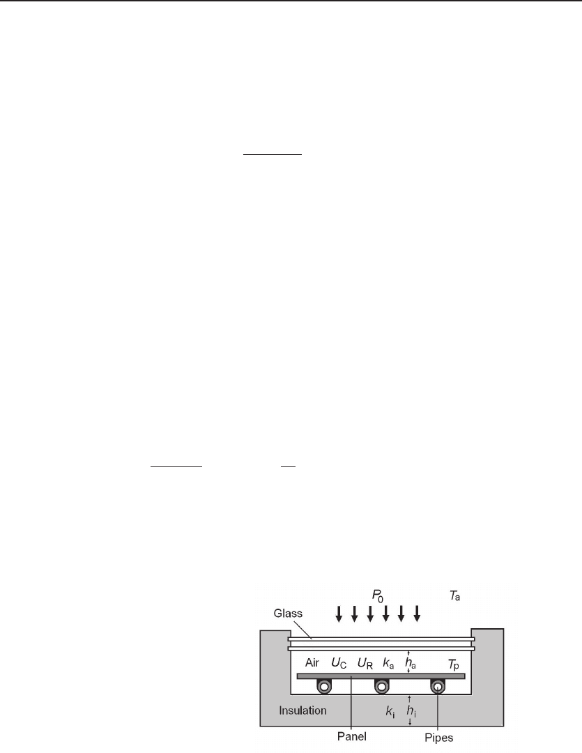
Figure 11.8 Flat-plate solar heat col-
lector. It is essentially a de Saussure hot
box, Fig. 11.2, hosting a copper plate with
copper pipes soldered on, painted black.
Usually one or two sheets of glass are in-
stalled for top-side heat insulation. Water
can be heated up to 60
◦
or 80
◦
by sunlight.
It is a quite rugged device which could last
for many decades.
i
i
“ChenSolarEnergy” — 2011/5/17 — 17:56 — page 234 — #261
i
i
i
i
i
i
234 Solar Thermal Energy
nontrivial. Many factors contribute to the loss through the front cover, and some of
them are quite difficult to quantify:
1. Conduction through the back-side insulation is easy to quantify, as the corre-
sponding loss factor equals k
i
/h
i
, the thermal conductivity and thickness of the
insulation material.
2. Conduction through the air space is also easy to quantify, as the corresponding
loss factor equals k
a
/h
a
, the thermal conductivity and thickness of air.
3. Convection in the air space is difficult to quantify. It has a complicated depen-
dence on spacing and the tilt angle.
4. Convection outside the glass cover depends not only the temperature but also the
wind speed of ambient air.
5. Radiation. The thermal radiation of the panel first reaches the glass panel. It
essentially absorbs most of the radiation. The glass panel, being heated, radiates
again to the ambient.
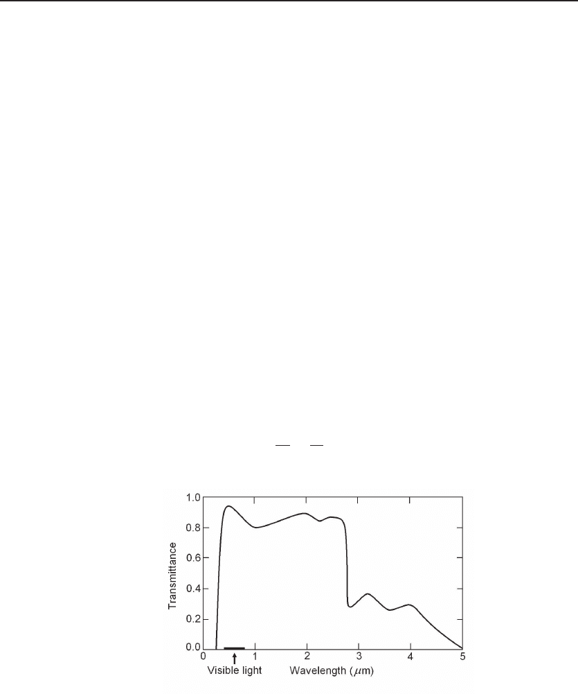
The transmittivity spectrum of common window glass is shown in Fig. 11.9. It is
transparent for visible and near-infrared radiation, but opaque for ultraviolet and far-
infrared radiation. The blackbody radiation from the hot plate is almost completely
absorbed by the glass.
The combined heat loss coefficient can be estimated as
U
L
=
k
a
h
a
+
k
i
h
i
+ U
C
+ U
R
. (11.12)
Figure 11.9 Transmittance of window glass. The window glass is transparent for the visible and
near-infrared radiation, but opaque for ultraviolet and far-infrared radiation. The blackbody radiation
from the hot plate is almost completely absorbed by the glass. Plotted using the data from American
Institute of Physics Handbook.
i
i
“ChenSolarEnergy” — 2011/5/17 — 17:56 — page 235 — #262
i
i
i
i
i
i
11.2 Solar Heat Collectors 235
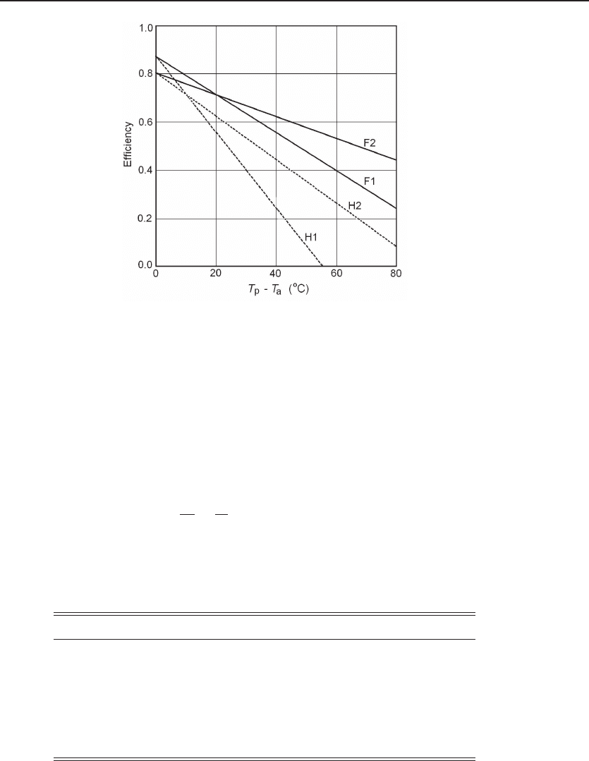
Figure 11.10 Efficiency of flat-plate collectors. Dependence of efficiency on solar radiation
power and temperature rise. Curve F1 shows the efficiency under full sunlight, 1 kW/m
2
,withone
glass cover; F2 for two glass covers. Curve H1 shows the efficiency under one-half of full sunlight, 0.5
kW/m
2
, with one glass cover; H2 for two glass covers. As the temperature of the plate increases, the
efficiency deteriorates rapidly due to the heat loss via the top glass cover. At some point, the heat loss
exceeds the solar energy received by the panel, and the efficiency becomes zero.
Where k
a
and k
i
are the thermal conductivities of the air and insulation material,
respectively, h
a
and h
i
are the thicknesses of the air and insulation wall, respectively
(see Fig. 11.8), U
C
is the convection heat loss coefficient, and U
R
is the radiation heat
loss coefficient. The first two terms can be estimated using the typical parameters
listed in Table 11.2,
k
a
h
a
+
k
i
h
i
≈ 1.36 (W/m
2
· K). (11.13)
However, the last two terms are usually much larger than the first two. An effective
Table 11.2: Typical Parameters of Flat-Plate Solar Heat Collectors
Parameter Description Symbol Unit Value
Cover glass Refractive index n —1.50
Panel Absorptance α —0.95
Insulation Thermal conductivity k
i
W/m
2
·K0.02
Insulation Thickness d
i
meter 0.05
Air space Thermal conductivity k
a
W/m
2
·K 0.024
Air space Thickness d
a
m 0.025
i
i
“ChenSolarEnergy” — 2011/5/17 — 17:56 — page 236 — #263
i
i
i
i
i
i
236 Solar Thermal Energy
way to reduce convection and radiation loss is to increase the number of sheets of glass.
According to the calculations of Duffie and Beckman [23, 24], under normal conditions
(wind speed 5.0 m/s, average plate temperature 60
◦
C, slope 45
◦
, ambient temperature
minus20–40
◦
C), the top loss coefficient is 6.9 W/m
2
·K for one cover, 3.5 W/m
2
·K
for two covers, and 2.4 W/m
2
·K for three covers. However, more covers result in more
loss of transmittance. From Eq. 11.8, the transmittance of one sheet of glass is 0.92.
It is reduced to 0.85 for two sheets, and 0.782 for three sheets. Therefore, using three
covers does not represent an advantage.
The efficiency also depends on the power density of solar radiation. Because the
heat loss is independent of the solar radiation, the weaker the solar radiation, the lower
the efficiency. Figure 11.10 shows a typical dependence of efficiency on solar radiation
power and temperature rise. Curve F1 shows the efficiency under full sunlight, 1
kW/m
2
, with one glass cover; F2 shows it for two glass covers. Curve H1 shows the
efficiency under one-half of full sunlight, 0.5 kW/m
2
, with one glass cover; H2 for two
glass covers. For simplicity, the area ratio F is assumed to be 1, which is approximately
true in most practical cases. As the temperature of the plate increases, the efficiency
deteriorates rapidly due to the heat loss via the top glass cover. At some point, the
heat loss exceeds the solar energy received by the panel. And the efficiency becomes
negative: The temperature of the plate falls instead of rises.
11.2.3 All-Glass Vacuum-Tube Collectors
As shown in the previous section, the single most important factor affecting the effi-
ciency of solar heat collectors is the heat loss through the top cover. As early as 1911,
William L. R. Emmet invented vacuum tube heat collectors (U.S. Patent 980,505)
which could in principle completely resolve the problem of top-cover heat loss. It took
80 years to make them suitable for mass production.
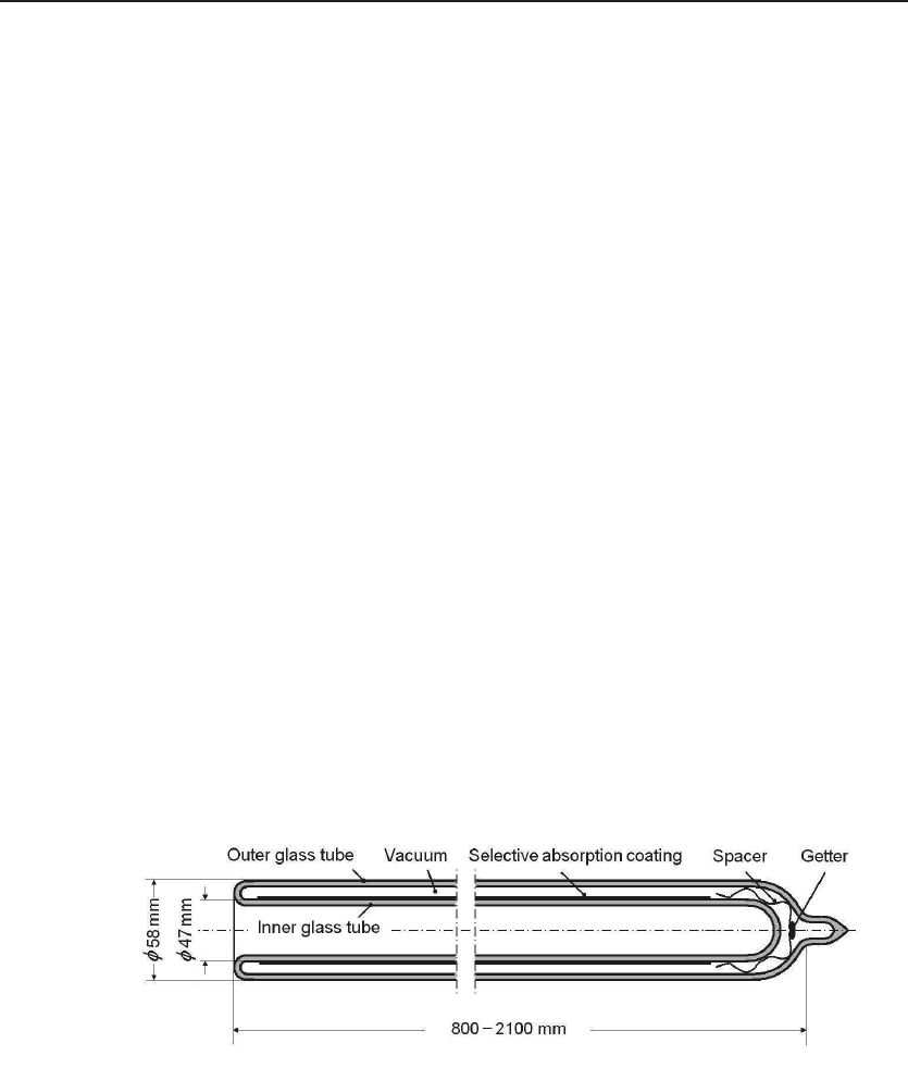
Figure 11.11 shows a modern evacuated-tube solar thermal collector. It is made
of two concentric glass tubes sealed at one end. The space in between is evacuated
Figure 11.11 Evacuated-tube solar thermal collector. It is made of two concentric glass tubes
sealed at one end. The space in between is evacuated to better than 10
−4
Pa, or 10
−6
Torr. A metal
spacer is placed as a source for the getter, typically a mixture of barium and titanium. After it is
sealed, the getter is evaporated onto the inner surface of the glass tubes. A high vacuum thus can be
maintained. A selective absorption coating is applied on the outer surface of the inner glass tube.
i
i
“ChenSolarEnergy” — 2011/5/17 — 17:56 — page 237 — #264
i
i
i
i
i
i
11.2 Solar Heat Collectors 237
to a medium high vacuum. A metal spacer is placed between the tubes to support
the tubes and as a source for getter, typically a mixture of barium and titanium.
After being sealed, the getter support is heated from outside using microwave power to
evaporate the getter onto the inner surface of the glass tubes. A high vacuum thus can
be maintained. Good-quality evacuated tubes should have a vacuum better than 10
−4
Pa, or 10
−6
Torr. A selective absorption coating is applied on the outer surface of the
inner glass tube. Therefore, the selective coating is always under high vacuum. It has
a significant advantage over the flat-panel heat collector as a selective coating stable in
air is not required and the coating could stay intact virtually forever. Furthermore, an
antireflection film can be applied on top of the selective absorption coating even if the
film is not stable in air.
Another advantage over the flat-panel heat collector is that the materials are inex-
pensive and abundant and can be mass produced at very low cost. To date, 200 million
evacuated tubes are produced annually in China.
An important consideration is that the area ratio F is much less than 1 for vacuum
tube collectors, because the diameter of the inner tube determines the absorption area,
and when the tubes are installed on a system, there should be spacing between adjacent
outer tubes. Typically the space is 20 mm. The typical area ratio F =47/(58 + 20) ≈
0.6. The smaller factor F actually is not a serious disadvantage. First, in residential
applications, there is always more roof space than needed. Second, An important
consideration is the cost of the solar thermal energy collector. Because there is empty
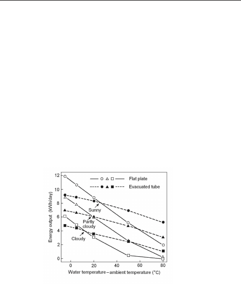
Figure 11.12 Performance comparison of flat-panel and evacuated-tube collectors. For
sunny weather and low T
p
− T
a
requirements, the flat-panel system clearly has an advantage because of
the high area ratio F . For cloudy weather and high T
p
− T
a
requirements, the evacuated-tube system
is better because convection and conduction losses are eliminated. After a report by William Ferguson
on Wikipedia.
i
i
“ChenSolarEnergy” — 2011/5/17 — 17:56 — page 238 — #265
i
i
i
i
i
i
238 Solar Thermal Energy
space between the tubes, there is no additional cost. Third, because of the empty space,
there is no additional weight on the roof. Finally, if the sunlight is not perpendicular
to the plane of the tubes, up to an angle of incidence θ = arccos(F ), maximum power
can be maintained.
Figure 11.12 compares the performance of solar water heaters using flat-panel col-
lectors and evacuated-tube collectors. The flat-panel solar water heater is the Thermo-
Dynamics S42-P and the evacuated-tube system is the SunMaxx 20EVT. The result
was reported by William Ferguson on Wikipedia. For sunny weather and low T
p
− T
a
requirements, the flat-panel system clearly has an advantage because of the high value
of area ratio F . For cloudy weather and high T
p
−T
a
requirements, the evacuated-tube
system is superior because convection and conduction losses are eliminated. Further-
more, high-performance selective absorption coating can be used because there is no
requirement of air stability, and the radiation loss becomes negligible. The heat loss
observed here for vacuum-tube systems is due to the heat loss of the water tank. The
general trend is consistent with the analysis in this section.
11.2.4 Thermosiphon Solar Heat Collectors
Evacuated-tube solar energy collectors are used primarily for direct-flow solar water
heaters, where the usable water goes directly into the tubes. It has very high effi-
ciency. However, the hot water could be contaminated by the system, and the pressure
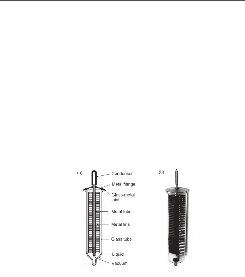
Figure 11.13 Thermosiphon solar heat collector. (a) Structure of a thermosiphon solar heat
collector. At the center is a sealed metal tube, typically made of copper. A small amount of volatile
liquid is filled in the metal tube, typically water. The metal tube is connected with metal fins, covered
with selective absorption coatings. The metal tube is mounted on a metal flange, typically stainless
steel. A glass-metal joint is formed between the flange and the glass tube. A vacuum is drawn in the
glass tube. (b) Photograph of the collector. With sunlight falling on the metal fins, the liquid in the
metal tube is evaporated, than condensed at the top, which is thermally connected to a heat load.
i
i
“ChenSolarEnergy” — 2011/5/17 — 17:56 — page 239 — #266
i
i
i
i
i
i
11.2 Solar Heat Collectors 239
comes directly from gravitation. For systems requiring pressurized hot water and more
stringent sanitation, thermosiphon solar heat collectors are used.
Figure 11.13(a) shows a cross section of a thermosiphon solar heat collector. At
the center is a sealed metal tube typically made of copper. A small amount of volatile
liquid is in the metal tube, typically water. The metal tube is connected with metal
fins covered with selective absorption coatings. The metal tube is mounted on a metal
flange, typically stainless steel. A glass–metal joint is formed between the flange and
the glass tube. A vacuum is drawn in the glass tube. Figure 11.13(b) is a photo of the
device. The tube must be installed at a tilted position with the evaporator at the top.
With sunlight falling on the metal fins, the liquid in the metal tube is evaporated, then
condensed at the top, which is thermally connected to a heat load.
A key technical problem is formation of the glass–metal joint. A widely used tech-
nology is a metal gasket of relatively low melting point, such as tin, lead, or aluminum.
By heating the joint under pressure at a temperature lower but close to the melting
point of the metal gasket, a good joint can be formed. The high vacuum in the tube
constantly exerts pressure on the glass–metal joint; therefore, the probability of a leak-
age is small. Compared with all-glass vacuum tubes, thermosiphon solar heat collectors
have several advantages. First, because there is no running water in the tubes, it can
withstand bitter cold without breaking the glass. Second, because the thermal mass
of the tube is much smatter than the water in the all-glass tubes, the start-up time
is much shorter. Third, even if one of the glass tubes is broken, for example, by hail
impact, there is no water leakage. Fourth, because hot water does not flow in the tubes,
the tank can be pressurized and run high-standard clean water. Lastly, because the
liquid returns to the bottom of the siphon tube by gravity, there is a thermal diode
effect — the heat only flows from the collector to the tank and cannot be reversed.
However, because of the metal structure and the glass–metal joint, the cost is much
higher than the all-glass tubes. Therefore, it is used in high-end solar water heaters.
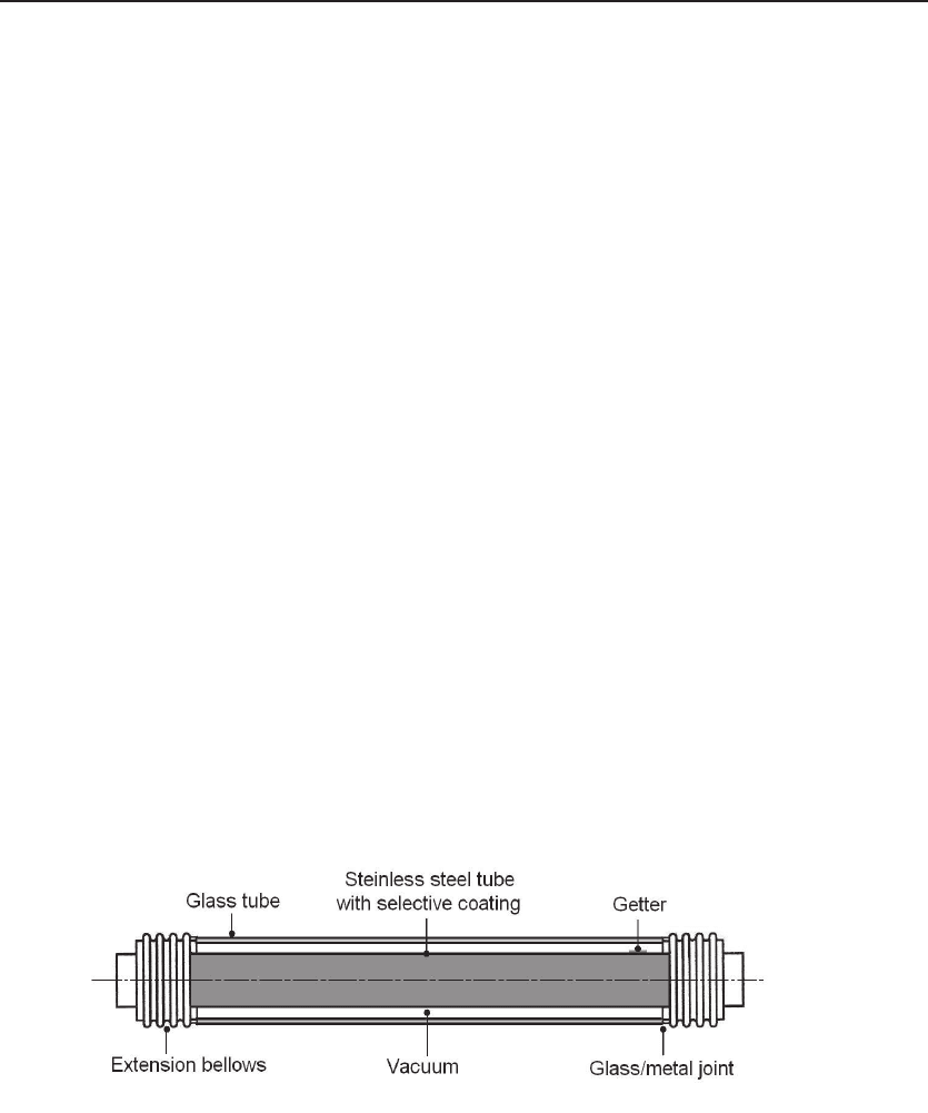
Figure 11.14 High-pressure vacuum tube collector. At the core is a stainless steel tube coated
with a selective absorption film. Both ends are fitted with extension bellows. Through a glass–metal
joint, each side is attached to an end of the glass tube. A vacuum is drawn between the stainless tube
and the glass tube. A getter is included to maintain a good vacuum.
i
i
“ChenSolarEnergy” — 2011/5/17 — 17:56 — page 240 — #267
i
i
i
i
i
i
240 Solar Thermal Energy
11.2.5 High-Pressure Vacuum Tube Collectors
For solar thermal applications, the working fluid inside the tube is not hot water. It is
either oil at high temperature (300
◦
C or more) or superheated steam at high pressure
(10 – 100 atm). The glass tube would not withstand such temperature and pressure.
The inner tube must be made of a strong metal, typically stainless steel. The outer
tube must be transparent, made of glass. Therefore, there is a problem of mismatch
of thermal expansion coefficients, and a metal–glass joint is required. The typical
structure of such a solar heat collector is shown in Fig. 11.14. At the core is a stainless
steel tube coated with a selective absorption film. Both ends are fitted with extension
bellows. Through a glass-metal joint, each side is attached to an end of the glass tube.
A vacuum is drawn between the stainless steel tube and the glass tube. A getter is
included to maintain a good vacuum.
11.3 Solar Water Heaters
The most popular solar water heater is the direct-flow system using all-glass evacuated-
tube solar heat collectors; see Section 1.5.3, especially Fig. 1.32. Usually it is installed
on the roof of a single-family house or an apartment building. The hot water flows
simply by gravitation. Because of low manufacturing cost as a result of large-scale
mass production, whenever such a system can could be used, the investment can be
recouped in a few years without government subsidy. After the initial cost is paid off,
the system can work properly for 20 – 30 years with no maintenance. In China alone,
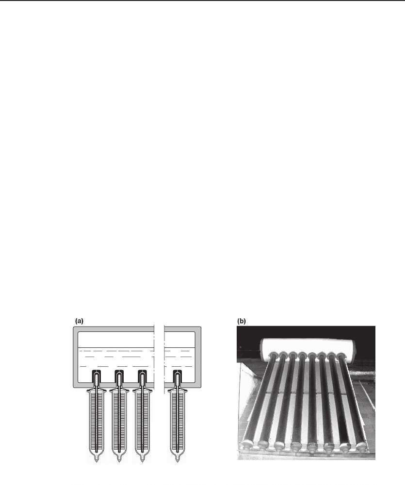
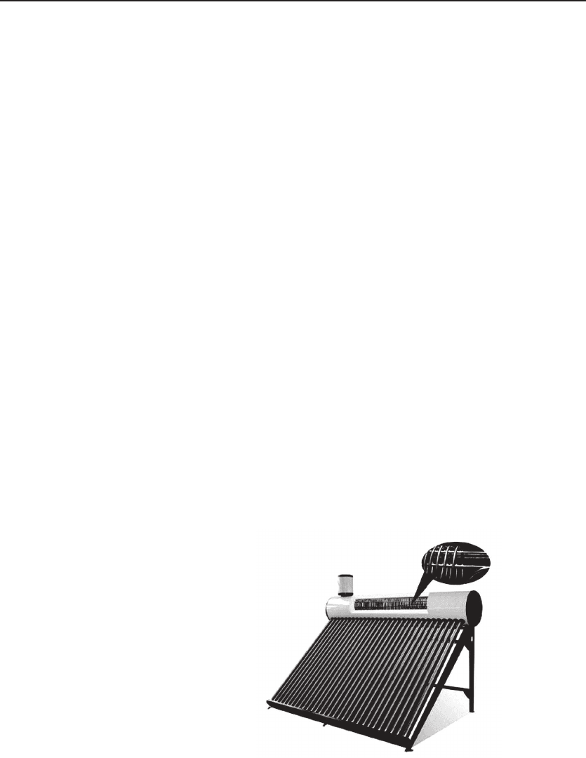
Figure 11.15 Solar water heater with thermosiphon collectors. (a) Design of the solar water
heater. The evaporators of the thermosiphon solar heat collector are in thermal contact with the water
in the tank through copper blocks. (b) A system on a roof after more than 10 years of operation. No
degradation is observed. Photo taken by the author.
i
i
“ChenSolarEnergy” — 2011/5/17 — 17:56 — page 241 — #268
i
i
i
i
i
i
11.3 Solar Water Heaters 241
more than 10 million such systems have been installed.
This simple and elegant system does have some disadvantages. The hot water
cannot be pressurized. Any contamination in the system would appear at the outlet. If
a single tube breaks, all the water will flow out immediately. Many improved systems
are developed and used.
11.3.1 System with Thermosiphon Solar Heat Collectors
By using the thermosiphon solar heat collectors instead of the all-glass evacuated tubes,
the running hot water makes no contact with the heat collectors. Heat transfer is
through the evaporators of the collector and the (usually copper) blocks inside the
water tank, see Fig. 11.15(a). The water inside the tank can be cleaned thoroughly.
If one of the collector tube breaks, the rest of the collector tubes will keep the system
running, although the power is slightly reduced, until a replacement collector tube is
reinstalled. Figure 11.15(b) shows a photo of such system on a roof after more than 10
years of operation. No degradation is observed.
11.3.2 System with Pressurized Heat-Exchange Coils
A much cleaner system can be formed by installing a heat exchange coil inside the
insulated water tank. The water in the evacuated tubes and the insulated water tank
is then used for heat exchange only; see Fig. 11.16. The usable hot water runs only
in the heat exchange coil and thus can be pressurized and will not be contaminated
by the heat collecting system. The insert in Fig. 11.16 shows some detail of the heat
exchange coil.
Figure 11.16 Solar wa-
ter heater with pressurized
heat exchange coils. The
hot water only runs in the heat
exchange coil inside the insu-
lated tank. Therefore, the hot
water can be pressurized and
will not be contaminated by
the heat-collecting system. In-
sert shows some detail of the
heat exchange coil.
i
i
“ChenSolarEnergy” — 2011/5/17 — 17:56 — page 242 — #269
i
i
i
i
i
i
242 Solar Thermal Energy
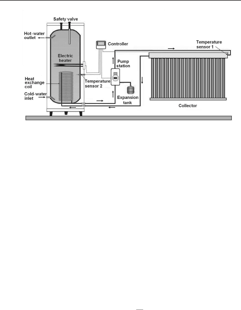
Figure 11.17 System with separate heat exchange tank. The solar heat collector is filled
with a heat exchange fluid, circulated by a pump. The temperature of the water tank is sensed by
thermometer 2. The temperature of the outlet water can be preset using a controller, which controls
the pump station.
11.3.3 System with a Separate Heat-Exchange Tank
Using a separate water tank and a heat exchange coil inside the tank, the usable hot
water is completely isolated from the heat collectors. The typical structure of such a
system is shown in Fig. 11.17.
The solar heat collector is filled with a heat exchange fluid which can be water
or an antifreeze fluid, for example, a mixture of water and glycerol. In a flat-panel
solar collector, in regions with freezing temperature, antifreeze fluid is a necessity. In
evacuated-tube collectors, because of the superb insulation, ordinary water can be used.
The heat exchange fluid is circulated with a pump. The temperature of the water tank
is sensed by a thermometer (2). The temperature of the outlet water can be preset
using a controller, which controls the pump station.
11.4 Solar Thermal Power Systems
A more important area of solar thermal application is electric power generation. Ac-
cording to the second law of thermodynamics, the upper limit of the efficiency of
converting heat to mechanical power is the Carnot efficiency (Eq.6.19),
η
c
=1−
T
L
T
H
, (11.14)