Dinc Ibrahim. Refrigeration systems and applications 2th edition
Подождите немного. Документ загружается.

Advanced Refrigeration Cycles and Systems 251
flowing through the nozzle 1. The expansion causes a drop in pressure and an enormous increase in
velocity. Owing to the high velocity, flash vapor from the tank 2 is drawn into the swiftly moving
steam and the mixture enters the diffuser 3. The velocity is gradually reduced in the diffuser but
the pressure of the steam at the condenser 4 is increased 5–10 times more than that at the entrance
of the diffuser (e.g., from 0.01 to 0.07 bar).
This pressure value corresponds to the condensing temperature of 40
◦
C. This means that the
mixture of high-pressure steam and the flash vapor may be liquefied in the condenser. The latent
heat of condensation is transferred to the condenser water, which may be at 25
◦
C. The condensate
5 is pumped back to the boiler, from which it may again be vaporized at a high pressure. The
evaporation of a relatively small amount of water in the flash tank (or flash cooler) reduces the
temperature of the main body of water. The cooled water is then pumped as the refrigeration carrier
to the cooling-load heat exchanger.
An ejector was invented by Sir Charles Parsons around 1901 for removing air from steam engine
condensers. In about 1910, the ejector was used by Maurice Leblanc in the steam ejector refriger-
ation system. It experienced a wave of popularity during the early 1930s for air conditioning large
buildings. Steam ejector refrigeration cycles were later supplanted by systems using mechanical
compressors. Since that time, development and refinement of ejector refrigeration systems have
been almost at a standstill as most efforts have been concentrated on improving vapor compression
cycles (Aphornratana et al., 2001).
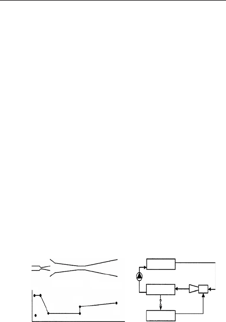
Furthermore, another typical gas-driven ejector is shown schematically in Figure 5.27a. High-
pressure primary fluid (P) enters the primary nozzle, through which it expands to produce a low-
pressure region at the exit plane (1). The high-velocity primary stream draws and entrains the
secondary fluid (S) into the mixing chamber. The combined streams are assumed to be completely
mixed at the end of the mixing chamber (2) and the flow speed is supersonic. A normal shock
wave is then produced within the mixing chamber’s throat (3), creating a compression effect, and
the flow speed is reduced to a subsonic value. Further compression of the fluid is achieved as the
mixed stream flows through the subsonic diffuser section (b).
Figure 5.27b shows a schematic diagram of an ejector refrigeration cycle. It can be seen that a
boiler, an ejector, and a pump are used to replace the mechanical compressor of a conventional
system. High-pressure and high-temperature refrigerant vapor is evolved in a boiler to produce
the primary fluid for the ejector. The ejector draws vapor refrigerant from the evaporator as its
secondary fluid. This causes the refrigerant to evaporate at low pressure and to produce useful
refrigeration. The ejector exhausts the refrigerant vapor to the condenser where it is liquefied. The
liquid refrigerant accumulated in the condenser is returned to the boiler via a pump while the
Mixing chamber
Primary nozzle
Pressure
P
S
1
3
2
b
Boiler
Ejector
Condenser
Evaporator
Subsonic diffuser
(a)
(b)
Figure 5.27 Schematic of (a) a jet ejector and (b) a simple jet ejector refrigeration system (Aphornratana
et al., 2001).

252 Refrigeration Systems and Applications
remainder is expanded through a throttling valve to the evaporator, thus completing the cycle. As
the working input required to circulate the fluid is typically less than 1% of the heat supplied to
the boiler, the COP may be defined as the ratio of evaporator refrigeration load to heat input to the
boiler as follows:
COP =
˙
Q
L
˙
Q
B
(5.66)
where
˙
Q
L
is evaporator refrigeration load in kW and
˙
Q
B
is heat input to the boiler in kW.
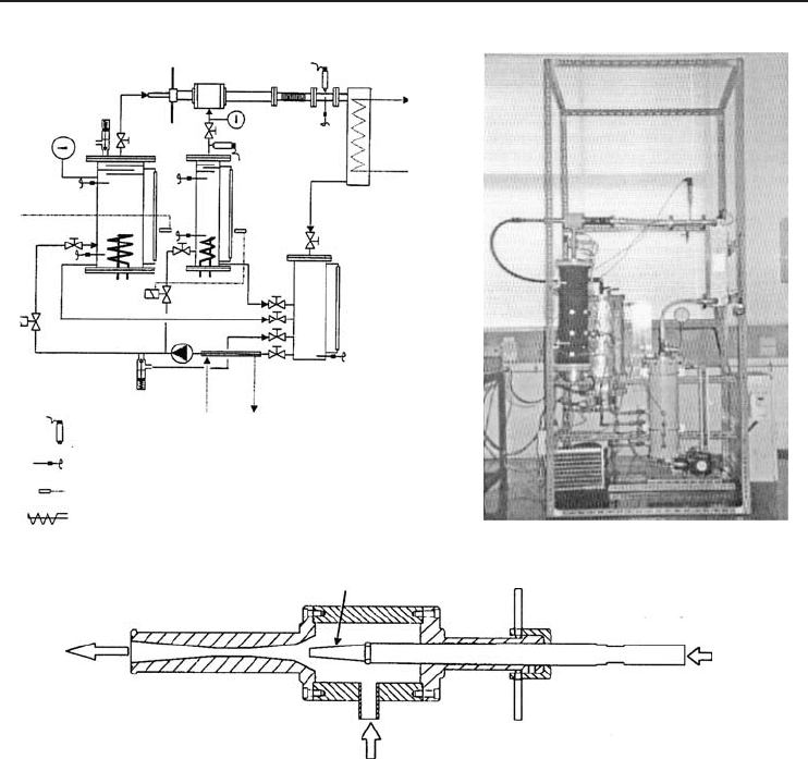
In the past, Aphornratana et al. (2001) have developed a new jet ejector refrigeration system
using R-11 as the refrigerant as shown in Figure 5.28. All vessels in the systems were constructed
from galvanized steel. The boiler was designed to be electrically heated, with two 4 kW electric
heaters being located at the lower end. At its upper end, three baffle plates were welded to the vessel
to prevent liquid droplets being carried over with the refrigerant vapor. The evaporator design was
similar to that of the boiler. A single 3 kW electric heater was used to simulate a cooling load.
A water-cooled plate type heat exchanger was used as a condenser. Cooling water was supplied at
32
◦
C. The boiler was covered with 40 mm thickness of glass wool with aluminum foil backing.
The evaporator was covered with 30 mm thickness of neoprene foam rubber. A diaphragm pump
was used to circulate liquid refrigerant from the receiver tank to the boiler and the evaporator.
The pump was driven by a variable-speed 1/4 hp motor. One drawback of using the diaphragm
pump is cavitation of the liquid refrigerant in the suction line due to pressure drop through an
inlet check valve. Therefore, a small chiller was used to subcool the liquid R-11 before entering
the pump. Figure 5.28c shows a detailed schematic diagram of the experimental ejector. The
nozzle was mounted on a threaded shaft, which allowed the position of the nozzle to be adjusted.
A mixing chamber with throat diameter of 8 mm was used: in the inlet section of the mixing
chamber, the mixing section is a constant are a duct while in the exit section, the mixing section
is a convergent duct.
Aphornratana et al. experiments showed that an ejector refrigeration system using R-11 proved
to be practical and could provide reasonably acceptable performance. It can provide a cooling
temperature as low as −5
◦
C. The cooling capacity ranged from 500 to 1700 W with COP ranging
from 0.1 to 0.25.
5.6 Thermoelectric Refrigeration
This type of system is used to move heat from one area to another by the use of electrical energy. The
electrical energy, rather than the refrigerant, serves as a “carrier.” The essential use of thermoelectric
systems has been in portable refrigerators, water coolers, cooling of scientific apparatus used in
space exploration, and in aircraft. The main advantage of this system is that there are no moving
parts. Therefore, the system is compact, quiet, and needs little service.
Thermoelectric coolers are solid state equipment used in applications where temperature sta-
bilization, temperature cycling, or cooling below ambient temperature are required. There are
many products using thermoelectric coolers, including charge-coupled device (CCD) cameras, laser
diodes, microprocessors, blood analyzers, and portable picnic coolers.
Thermoelectrics are based on the Peltier Effect, discovered in 1834, by which DC current applied
across two dissimilar materials causes a temperature differential. The Peltier effect is one of the three
thermoelectric effects, the other two being known as the Seebeck effect and Thomson effect . Whereas
the last two effects act on a single conductor, the Peltier effect is a typical junction phenomenon.
The three effects are connected to each other by a simple relationship (Godfrey, 1996).
The typical thermoelectric module is manufactured using two thin ceramic wafers with a series of
P- and N-doped bismuth telluride semiconductor materials sandwiched between them. The ceramic
material on both sides of the thermoelectric adds rigidity and the necessary electrical insulation.
Advanced Refrigeration Cycles and Systems 253
(a)
(b)
(c)
Ejector
Boiler
Cooling water
Condenser
Evaporator
Receiver tank
To R12 chiller
Pressure transducer
Type K thermocouple
Liquid level sensor
Electric heater
Mixing chamber
To the condenser
From the evaporator
Primary nozzle
Nozzle position adjusting device
From the boiler
Figure 5.28 (a) Schematic of the experimental ejector refrigerator. (b) Photograph of the experimental refrig-
erator. (c) The ejector used in the experimental set-up (Aphornratana et al., 2001).
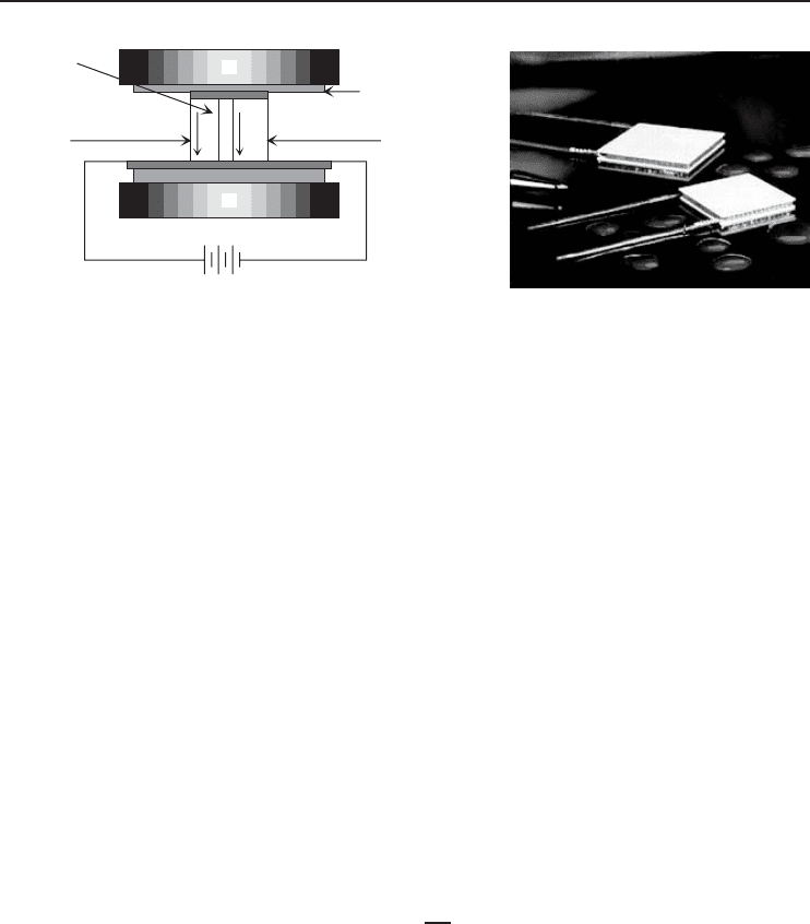
The N type material has an excess of electrons, while the P type material has a deficit of electrons.
One P and one N make up a couple, as shown in Figure 5.29. The thermoelectric couples are
electrically in series and thermally in parallel. A thermoelectric module can contain one to several
hundred couples. As the electrons move from the P type material to the N type material through
an electrical connector, the electrons jump to a higher energy state absorbing thermal energy (cold
side). Continuing through the lattice of material, the electrons flow from the N type material to
the P type material through an electrical connector, dropping to a lower energy state and releasing
energy as heat to the heat sink (hot side).
Thermoelectrics can be used to heat and to cool, depending on the direction of the current. In an
application requiring both heating and cooling, the design should focus on the cooling mode. Using
a thermoelectric in the heating mode is very efficient because all the internal heating (Joulian heat)
and the load from the cold side is pumped to the hot side. This reduces the power needed to achieve
the desired heating.
254 Refrigeration Systems and Applications
−
−
−
−
−−
−
+
+
+
+
+
+−
DC source
(a) (b)
Body to be cooled
(heat source)
Heat sink
“N” type
semiconductor
“P” type
semiconductor
Electrical insulation
(good heat conductor)
Electronic carriers
moving heat to
the heat sink
Figure 5.29 (a) Cross-sectional view of a typical thermoelectric cooler. (b) Practical thermoelectric coolers
(Courtesy of Melcor Corporation).
5.6.1 Significant Thermal Parameters
The appropriate thermoelectric for an application depends on at least three parameters. These
parameters are the hot surface temperature (T
h
), the cold surface temperature (T
c
), and the heat
load to be absorbed at the cold surface (
˙
Q
c
).
The hot side of the thermoelectric is the side where heat is released when DC power is applied.
This side is attached to the heat sink. When using an air-cooled heat sink (natural or forced
convection), the hot side temperature can be found using the following heat-transfer equation:
T
h
= T
a
+ R
˙
Q
h
(5.67)
where T
a
is the ambient temperature in
◦
C, R is the thermal resistance of the heat exchanger (
◦
C/W),
and
˙
Q
h
is the heat released to the hot side of the thermoelectric in W.
The heat-transfer balance equation for the thermoelectric cooler becomes
˙
Q
h
=
˙
Q
c
+
˙
W (5.68)
where
˙
Q
c
is the heat absorbed from the cold side in W and
˙
W is the electrical input power to the
thermoelectric cooler in W. The COP of a thermoelectric refrigerator is defined as
COP =
˙
Q
c
˙
W
(5.69)
Note that the thermal resistance of the heat sink causes a temperature rise above ambient temper-
ature. If the thermal resistance of the heat sink is unknown, then estimates of acceptable temperature
rise above ambient temperature are as follows (Godfrey, 1996):
• Natural convection: 20 to 40
◦
C
• Forced convection: 10 to 15
◦
C
• Liquid cooling: 2 to 5
◦
C (rise above the liquid coolant temperature).
The heat sink is a key component in the assembly. A heat sink that is too small means that
the desired cold side temperature may not be obtained. The cold side of the thermoelectric is the
side that gets cold when DC power is applied. This side may need to be colder than the desired
temperature of the cooled object. This is especially true when the cold side is not in direct contact
with the object, such as when cooling an enclosure.

Advanced Refrigeration Cycles and Systems 255
The temperature difference across the thermoelectric relates to T
h
and T
c
as follows:
T = T
h
− T
c
(5.70)
In a recent paper, Godfrey (1996) studied the thermoelectric performance curves and the rela-
tionship between the temperatures and the other parameters, as well as other parameters that are
required to calculate the thermal loads for the design. The thermal loads can be classified as follows:
• Active loads. I
2
R heat load from the electronic devices and any load generated by a chemical
reaction
• Passive loads. Radiation (heat loss between two close objects with different temperatures), con-
vection (heat loss through the air where the air has a different temperature than the object),
insulation losses, conduction losses (heat loss through leads, screws, etc.), and transient load
(time required to change the temperature of an object).
It is also important that all thermoelectrics are rated for I
max
, V
max
, Q
max
,andT
max
, at a specific
value of T
h
. Operating at or near the maximum power is relatively inefficient because of internal
heating (Joulian heat) at high power. Therefore, thermoelectrics generally operate within 25 to 80%
of the maximum current. The input power to the thermoelectric determines the hot side temperature
and cooling capability at a given load. As the thermoelectric operates, the current flowing through
it has two effects: (i) the Peltier effect (cooling) and (ii) the Joulian effect (heating). The Joulian
effect is proportional to the square of the current. Therefore, as the current increases, the Joulian
heating dominates the Peltier cooling and causes a loss in net cooling. This cut-off defines I
max
for
the thermoelectric. In fact, for each device, Q
max
is the maximum heat load that can be absorbed by
the cold side of the thermoelectric. This maximum occurs at I
max
and V
max
, and with T = 0
◦
C.
The T
max
value is the maximum temperature difference across the thermoelectric. This maximum
occurs at I
max
and V
max
and with no load (Q
c
= 0 W). These values of Q
max
and T
max
are well
treated by Godfrey (1996).
Example 5.6
Suppose we have a thermoelectric application with a forced convection type heat sink with a
thermal resistance of 0.15
◦
C/W, an ambient temperature of 25
◦
C, and an object that needs to be
cooled to 5
◦
C. The cold side of the thermoelectric will be in direct contact with the object. The
hot side temperature is 35
◦
C and the electric current and voltage are 3.6 A and 10 V, respectively.
Determine the temperature difference across the thermoelectric T and the heat absorbed from the
cold side
˙
Q
c
. Also, determine the COP of the system.
Solution
The temperature difference across the thermoelectric is
T = T
h
− T
c
= 35 − 5 = 30
◦
C
The heat released to the hot side of the thermoelectric is
T
h
= T
a
+ R
˙
Q
h
⇒
˙
Q
h
=
T
h
− T
a
R
=
(35 − 25)
◦
C
0.15
◦
C/W
= 66.7W
Then the heat absorbed from the cold side becomes
˙
Q
c
=
˙
Q
h
−
˙
W ⇒
˙
Q
c
=
˙
Q
h
− IV = 66.7W− (3.6A)(10 V)
1W
1AV
= 30.7W

256 Refrigeration Systems and Applications
TheCOPofthesystemis
COP =
˙
Q
c
˙
W
=
30.7 W
36 W
= 0.853
5.7 Thermoacoustic Refrigeration
Garrett and Hofler (1992) pointed out that two recent events are responsible for the new era in
refrigeration before the beginning of the twenty-first century. The most significant of these is the
international agreement (signing of the Montreal Protocol) on the production and consumption of
chlorofluorocarbons (CFCs), which were found to be causing the depletion of the stratospheric
ozone layer. The second event was the discovery of “high-temperature” superconductors and the
development of high-speed and high-density electronic circuits, which require active cooling and
hence a new approach to refrigeration, or thermoacoustic refrigeration, which was first discovered
by Wheatley et al. (1993) in August 1983. The simplicity of the hardware involved in thermoacous-
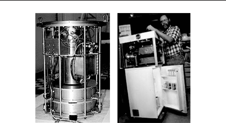
tic machines is best appreciated by examining a concrete example. In the mid-1990s, S.L. Garrett
and his colleagues at the Naval Postgraduate School in Monterey, California, developed two ther-
moacoustic refrigerators for the Space Shuttle. The first was designed to cool electronic components
and the second was intended to replace the refrigerator-freezer unit used to preserve blood and urine
samples from astronauts engaged in biomedical experiments (Garrett and Backhaus, 2000).
Thermoacoustic refrigeration is considered a new technology, attaining cooling without the need
for refrigerants. The basic mechanism is very simple and efficient. A loudspeaker creates sound
in a hollow tube which is filled with an ordinary gas. In fact, thermoacoustic refrigeration utilizes
high-density sound waves to transfer heat due to the thermoacoustic effect (i.e., acoustic energy).
Therefore, the working fluid in this system is acoustically driven gas. The process itself utilizes
standing acoustic waves in an enclosed cavity to generate the mechanical compression and expansion
of the working fluid (gas in this case) needed for the cooling cycle. The technique has the potential
for high-efficiency operation without the need for cooling liquids or mechanical moving parts.
These factors make the concept amenable to miniaturization to chip-scale dimensions for thermal
management of electronic components.
The interaction between acoustics and thermodynamics has been known ever since the dispute
between Newton and Laplace over whether the speed of sound was determined by the adiabatic or
isothermal compressibility of air. At the present time, the efficiency of thermoacoustic refrigerators
is 20−30% lower than their vapor-compression refrigerators. Part of that lower efficiency is due
to the intrinsic irreversibilities of the thermoacoustic heat transport process. These intrinsic irre-
versibilities are also the favorable aspects of the cycle, since they make for mechanical simplicity,
with few or no moving parts. A greater part of the inefficiency of current thermoacoustic refrigera-
tors is simply due to technical immaturity. With time, improvements in heat exchangers and other
subsystems should narrow the gap. It is also likely that the efficiency in many applications will
improve only because of the fact that thermoacoustic refrigerators are well suited to proportional
control. One can easily and continuously control the cooling capacity of a thermoacoustic refrig-
erator so that its output can be adjusted accurately for varying load conditions. This could lead to
higher efficiencies than for conventional vapor-compression chillers which have constant displace-
ment compressors and are therefore only capable of binary (on/off) control. Proportional control
avoids losses due to the start-up surges in conventional compressors and reduces the inefficiencies
in the heat exchangers, since such systems can operate over smaller temperature gaps between the
coolant fluid and the heat load.
The research focus of the Thermoacoustics Laboratory in ARL at Pennsylvania State Univer-
sity in cooperation with Los Alamos Research Laboratory is the study of acoustically driven heat
transport. Their goals include an improved understanding of fundamental thermoacoustic processes
and the development of new thermoacoustic refrigerators and heat engines with increased power
Advanced Refrigeration Cycles and Systems 257
(a)
(b)
Figure 5.30 (a) A thermoacoustic refrigerator and (b) its application to a refrigerator (Courtesy of Pennsylvania
State University Applied Research Laboratory).
density, temperature span, and efficiency, and the commercialization of those devices. The labora-
tory provides the infrastructure to support research on the basic processes required to understand
this emerging, environmentally friendly refrigeration technology. This facility also supports the
fabrication and testing required to produce complete, full-scale operational prototype refrigeration
systems for military and commercial applications such as food refrigerators/freezers and air condi-
tioners. Their prototypes have been flown on the Space Shuttle and have been used to cool radar
electronics onboard a US Navy warship. Thermoacoustic refrigerators with cooling powers ranging
from a few watts to chillers with cooling capacities in excess of 10 kW are currently in operation or
under construction. Figure 5.30a shows a thermoacoustic refrigerator developed by this laboratory
and it is operational for running a small refrigerator such as in Figure 5.30b.
Although thermoacoustic refrigerators have not been commercialized yet and are considered
to be still at a developmental stage, it is known that they can be used for any kind of cooling.
Conventional, single-stage, electrically operated thermoacoustic refrigerators can reach cold side
temperatures that are two-thirds to three-quarters of ambient temperature, so they are not well
suited to cryogenic applications below −40
◦
C. However, thermoacoustically driven pulse-tube style
refrigerators can reach the cryogenic temperatures required to liquefy air or natural gas. In their early
commercial stages, they will probably be limited to niche applications such as in military systems
which are required to operate in closed environments and food merchandizing where toxicity
is an important issue. As global environmental mandates and legislations/amendments become
essential, one can expect the scope of thermoacoustic applications to expand both domestically and
in emerging markets.
5.8 Metal Hydride Refrigeration Systems
For the first time, a group of Japanese companies (JNT, 1996) have succeeded in making operational
an innovative, CFC-free, metal hydride (MH) refrigeration system using hydrogen absorbing alloys
(MH alloys) for cold storage at low temperatures. Their state-of-the-art MH refrigeration system can
keep the temperature in a cold storage area below −30
◦
C. This was a real landmark in the field. The

258 Refrigeration Systems and Applications
joint R&D group in 1995 demonstrated an MH refrigeration system under test conditions by cooling
a 100 m
3
cold storehouse. They succeeded in continuously operating the system with a store room
temperature below −30
◦
C. The MH system can be made as compact in size as a conventional vapor-
compression refrigeration system. The system can be incorporated easily, therefore, into automatic
vending machines and display cabinets for frozen foods. At the end of the year, the group also
completed a trial model of an automatic vending machine equipped with an MH refrigeration system
which can be used for commercial operation once the system size has been reduced. In addition,
the system is safe since hydrogen is absorbed and stored in MH alloys. Ammonia absorption
refrigerating machines have also been proposed as an alternative CFC-free system for cold storage.
However, it is not possible to make ammonia systems as small in size as MH systems, and the
strong toxicity and highly irritating odor of ammonia are serious obstacles to their widespread use.
JNT (1996) stated that the MH refrigeration system is a very safe as well as clean and environ-
mentally friendly, CFC-free refrigeration system. Hydrogen is sealed in gas-tight cylinders, and,
being far lighter than air, rapidly diffuses into the atmosphere in the accidental event of its leakage.
Thus, the danger of explosion caused by hydrogen is slight. In addition, their system has additional
advantages as follows:
• By not using CFCs or ammonia, the system is applicable to wide-ranging uses.
• The system needs a heating source to generate energy for refrigeration, but can save energy
consumption for this purpose by the use of waste heat or by operating in combination with a
cogeneration system.
• It has no moving elements except for pumps circulating water and brine. In particular, its hydrogen
system, driven solely by heat input, does not need the manipulation of valves. Thus, rarely
suffering breakdowns, the MH system is easy and simple to operate and maintain.
• Driven by heat, the system consumes 20% less electric power than conventional, electrically
powered compression refrigeration machines.
• Having no sliding and vibrating components such as compressors, the system operates with low
noise levels.
• Because the MH refrigeration system is safe and simple to control, it is possible to design
refrigerating units using this technology with wide varieties of cooling capacities ranging from
10−10,000 kW.
5.8.1 Operational Principles
When MH alloys (e.g., TiZrCrFe series) come into contact with hydrogen, the alloys absorb hydro-
gen by an exothermic reaction and store it as MHs. In reverse, the alloys easily dissociate and
discharge hydrogen by an endothermic reaction. Employing this endothermic reaction when MH
alloys discharge hydrogen, MH refrigeration systems implement a refrigeration cycle by a combi-
nation of two types of alloys. One type works at a higher temperature and the other at a lower
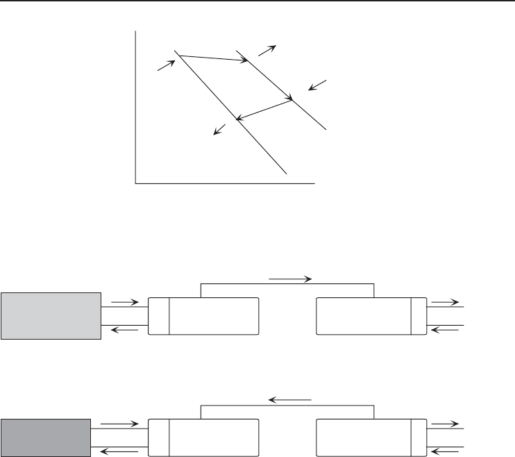
temperature, both under their own equilibrium hydrogen pressure. The working principles of MH
refrigeration systems are illustrated in Figure 5.31.
MH alloys absorb or discharge hydrogen at certain constant equilibrium hydrogen pressure levels,
determined by temperature. MH refrigeration systems use an MH alloy (MH-A) driving hydrogen
to carry out the regeneration process on the high-temperature side of the system and another MH
alloy (MH-B) refrigerating brine on the low-temperature side. Each of these alloys has the relation
between temperatures and equilibrium hydrogen pressures as shown in Figure 5.31a.
Regeneration Process. (1) To raise the hydrogen pressure of the MH-A by raising its temperature,
the alloy is heated (Q2-1). Hydrogen is discharged from the MH-A and moves to the MH-B
with lower hydrogen pressure. (2) The MH-B absorbs hydrogen, thus generating heat. However,
Advanced Refrigeration Cycles and Systems 259
MH-A MH-B
(Hydrogen driving alloy) (Refrigerating alloy)
Flow of hydrogen
MH-A MH-B
(Hydrogen driving alloy) (Refrigerating alloy)
Flow of hydrogen
High temperature
heat source
(steam or hot water)
Cooling water
Regenerative process : MH-A discharges hydrogen; MH-B absorbs/stores hydrogen
Refrigerating process : MH-B discharges hydrogen and refrigerates brine; MH-A absorbs/stores hydrogen
(Discharge) (Absorption/storage)
Brine for cooling of allo
y
Brine for refrigeration
12
3 (Absorption/storage) 4 (Discharge)
Q
2-1
Q
1-1
Q
2-2
Q
1-2
(b)
MH-A
MH-B
Q
2-1
Q
1-1
Q
2-2
Q
1-2
1
2
3
4
T
h
T
m
T
1
Temperature (1/T )
Pressure (log P )
(a)
Figure 5.31 (a) Working principle of MH refrigeration system and (b) illustration of MH refrigeration system
principle (JNT, 1996).
the circulation of cooling brine (Q1-1) suppresses the rise in the MH-B temperature, thereby
preventing the pressure of the MH-B from increasing. The MH-B continues to absorb and store
hydrogen in this way.
Refrigeration Process. (3) When all the hydrogen of the MH-A is transferred to the MH-B, the
former alloy is cooled by cooling water (Q2-2), thereby lowering its hydrogen pressure. (4)
Hydrogen is discharged from the MH-B. This has a lower hydrogen pressure than that of the
MH-A and moves to the latter alloy. Reducing its temperature by the hydrogen discharge, the
MH-B refrigerates brine (Q1-2).
To continuously cool brine for refrigeration, an MH refrigeration system has two sets of high-
and low-temperature MH alloy pairs. While one set of the alloys operates in the regeneration
process, the other set works in the refrigeration process. Each of these MH alloys is packed in
a heat exchanger cylinder. This enables the exchange of thermal energy with a heating medium
(steam, hot water, etc.), cooling water, or brine. Shell and tube type heat exchangers are used.
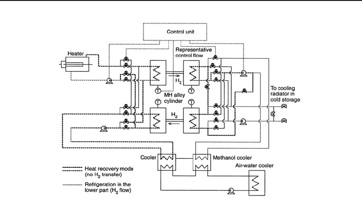
260 Refrigeration Systems and Applications
Figure 5.32 Flow chart of the MH refrigeration system for low-temperature cold storage (JNT, 1996).
The joint R&D group (JNT, 1996) applied this MH refrigeration system for a low-temperature
cold storage, using methanol as the heat-transfer medium for the low-temperature side and
hot/cooling water as the heat-transfer medium for the high-temperature side (Figure 5.32). MH
alloy cylinders (heat exchangers) are shown as forming part of the refrigerating process.
5.9 Solar Refrigeration
The developing worldwide shortage of petroleum emphasizes the need for alternative energy sources
which are both inexpensive and clean. There has been high interest in, and high potential use of,
renewable energy sources since the energy crisis faced during the 1970s. During the last few
decades, an increasing effort based on research and development has been concentrated on the
utilization of renewable energy sources, for example, solar energy, wind energy, tidal waves, biogas,
geothermal energy, hydropower, and hydrogen energy. Among these sources, solar energy for
refrigeration applications is very popular because it is direct and easy to use, renewable, and
continuous, maintains the same quality, is safe and free, and is environmentally friendly.
The continuous supply of solar energy to the earth’s surface is equal to a power of about 100,000
TW. Approximately one-third of the radiation impinging on land area and accumulated over less
than 2 hours should suffice to satisfy the entire primary energy demand by humans for the period of
1 year (Dincer, 1997; 2003). More than 25% of the total energy in the world is consumed for heating
and cooling of buildings and providing hot water. Therefore, the diversion of this particular energy
demand to an alternative source would result in a substantial reduction in the world’s dependence on
fossil fuels. The annual incidence of solar energy on buildings in the United States is several times
the amount required to heat these buildings; approximately 10
15
kW·h of solar energy is received
on earth annually. It has been projected that by the year 2020 from 25 to 50% of the thermal energy
for buildings could be provided from the sun (Dincer et al., 1996). Consequently, solar energy is an
available energy source for many applications ranging from electricity generation to food cooling.
5.9.1 Solar Refrigeration Systems
Many food products (e.g., fruits, vegetables, meats, dairy products) are stored in cooling units
for periods of the order of weeks at temperatures between 0 and 4
◦
C in order to prevent