Menon E.S. Liquid Pipeline Hydraulics
Подождите немного. Документ загружается.

Pressure and Horsepower Required 93
the above example as follows:
Brake horsepower=Hydraulic horsepower/Pump efficiency
BHP=HHP/0.75-1552/0.75=2070
If an electric motor is used to drive the above pump, the actual motor
horsepower required would be calculated as
Motor HP=BHP/Motor efficiency
Generally induction motors used for driving pumps have fairly high
efficiencies, ranging from 95% to 98%. Using 98% for motor efficiency,
we can calculate the motor HP required as follows:
Motor HP=2070/0.98=2112
Since the closest standard-size electric motor is 2500 HP, this application
will require a pump that can provide a differential pressure of 950 psi at a
flow rate of 4000 bbl/hr and will be driven by a 2500 HP electric motor.
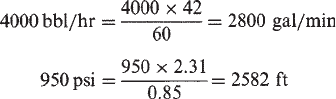
Pump companies measure pump flow rates in gal/min and pump
pressures are expressed in terms of feet of liquid head. We can therefore
convert the flow rate from bbl/hr to gal/min and the pump differential
pressure of 950 psi can be converted to liquid head in ft.
The above statement for the pump requirement can then be reworded as
follows: This application will use a pump that can provide a differential
pressure of 2582 ft of head at 2800 gal/min and will be driven by a 2500
HP electric motor. We discuss pump performance in more detail in
Chapter 7.
The formula for BHP required in terms of customary pipeline units is as
follows:
BHP=QP/(2449E) (5.16)
where
Q=Flow rate, bbl/hr
P=Differential pressure, psi
E=Efficiency, expressed as a decimal value less than 1.0
Copyright © 2004 by Marcel Dekker, Inc.
Chapter 594
Two additional formulas for BHP, expressed in terms of flow rate in gal/
min and pressure in psi or ft of liquid, are as follows:
BHP=(GPM)(H)(Spgr)/(3960E) (5.17)
and
BHP=(GPM)P/(1714E) (5.18)
where
GPM=Flow rate, gal/min
H=Differential head, ft
P=Differential pressure, psi
E=Efficiency, expressed as a decimal value less than 1.0
Spgr=Liquid specific gravity, dimensionless
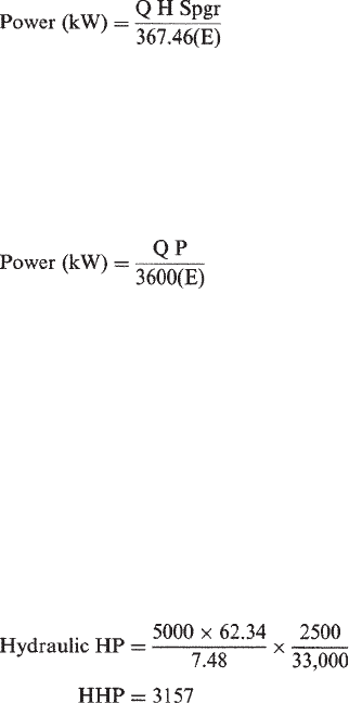
In SI units, power in kW can be calculated as follows:
(5.19)
where
Q=Flow rate, m
3
/hr
H=Differential head, m
Spgr=Liquid specific gravity
E=Efficiency, expressed as a decimal value less than 1.0
and
(5.20)
where
P=Pressure, kPa
Q=Flow rate, m
3
/hr
E=Efficiency, expressed as a decimal value less than 1.0
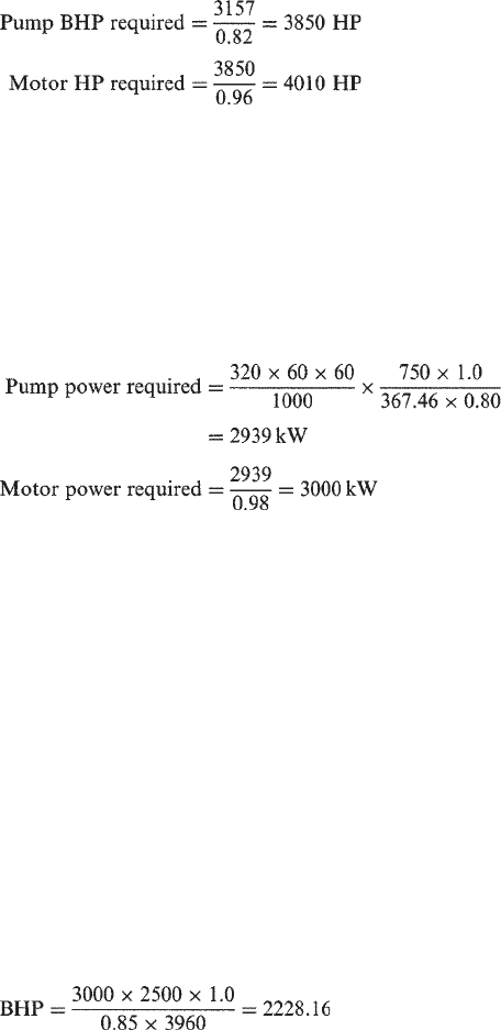
Example Problem 5.3
A water distribution system requires a pump that can produce 2500 ft head
pressure to transport a flow rate of 5000 gal/min. Assuming a centrifugal
pump driven by an electric motor, calculate the hydraulic HP, pump BHP,
and motor HP required at 82% pump efficiency and 96% motor efficiency.
Solution
Copyright © 2004 by Marcel Dekker, Inc.
Pressure and Horsepower Required 95
Example Problem 5.4
A water pipeline is used to move 320 L/s and requires a pump pressure of
750 m. Calculate the power required at 80% pump efficiency and 98%
motor efficiency.
Solution
Using Equation (5.20):
5.7 Effect of Gravity and Viscosity
It can be seen from the previous discussions that the pump BHP is directly
proportional to the specific gravity of the liquid being pumped. Therefore,
if the HP for pumping water is 1000, the HP required when pumping a
crude oil of specific gravity 0.85 is
Crude oil HP=0.85 (Water HP)=0.85×1000=850 HP
Similarly, when pumping a liquid of specific gravity greater than 1.0, the HP
required will be higher. This can be seen from examining Equation (5.17).
We can therefore conclude that, for the same pressure and flow rate, the
HP required increases with the specific gravity of liquid pumped. The HP
required is also affected by the viscosity of the liquid pumped. Consider
water with a viscosity of 1.0 cSt. If a particular pump generates a head of
2500 ft at a flow rate of 3000 gal/min and has an efficiency of 85%, we can
calculate the water HP using Equation (5.17) as follows:
If this pump is used with a liquid with a viscosity of 1000 SSU we must
correct the pump head, flow rate, and efficiency values using the Hydraulic
Copyright © 2004 by Marcel Dekker, Inc.
Chapter 596
Institute viscosity correction charts for centrifugal pumps. These are
discussed in more detail in Chapter 7. The net result is that the BHP
required when pumping the high-viscosity liquid will be higher than the
above calculated value. It has been found that with high-viscosity liquids
the pump efficiency degrades a lot faster than flow rate or head. Also,
considering pipeline hydraulics, we can say that high viscosities increase
the pressure required to transport a liquid and therefore increase the HP
required.
The effect of viscosity and specific gravity on pump performance will
be discussed in more detail in later chapters.
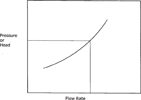
5.8 System Head Curves
A system head curve, also known as a system curve, for a pipeline shows
the variation of pressure required with flow rate. S
ee Figure 5.6 for a
typical system head curve. As the flow rate increases, the head required
increases.
Consider a pipeline of internal diameter D and length L used to
transport a liquid of specific gravity Sg and viscosity ν from a pump
station at A to a delivery point at B. We can calculate the pressure required
at A to transport the liquid at a particular flow rate Q. By varying flow rate
Q we can determine the pressure required at A for each flow rate such that
a given delivery pressure at B is maintained. For each flow rate Q, we
would calculate the pressure drop due to friction for the length L of the
Figure 5.6 System head curve.
Copyright © 2004 by Marcel Dekker, Inc.
Pressure and Horsepower Required 97
pipeline, add the head required to account for elevation difference between
A and B, and finally add the delivery pressure required at B as follows:
Pressure at A=Frictional pressure drop+Elevation head
+Delivery pressure, using Equation (5.1)
Once the pressure at A is calculated for each flow rate we can plot a system
head curve as shown in Figure 5.6. The vertical axis may be in feet of
liquid or psi. The horizontal axis will be in units of flow such as gal/min or
bbl/hr.
In Chapter 7 system head curves, along with pump head curves, will be
reviewed in detail. We will see how the system head curve in conjunction
with the pump head curve will determine the operating point for a
particular pump-pipeline configuration.
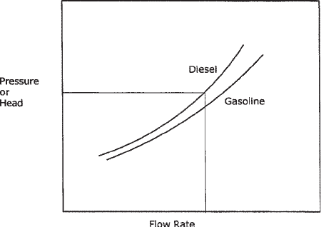
Since the system head curve represents the pressure required to pump
various flow rates through a given pipeline, we can plot a family of such
curves for different liquids as shown in Figure 5.7. The higher specific
gravity and viscosity of diesel fuel requires greater pressures compared
with gasoline. Hence the diesel system head curve is located above that of
gasoline as shown in Figure 5.7.
Note also that when there is no elevation difference involved the system
head curve will start at the (0, 0) point. This means that at zero flow rate
the pressure required is zero.
The shape of the system head curve varies depending upon the amount
of friction head compared with elevation head. Figures 5.8 and 5.9 show
two system head curves that illustrate this. In Figure 5.8 there is
Figure 5.7 System head curve: different products.
Copyright © 2004 by Marcel Dekker, Inc.

Chapter 598
comparatively less influence of the pipe elevations, most of the system
head required is due to the friction in the pipe. In comparison, Figure 5.9
shows a system head curve that consists mostly of the static head due to the
pipe elevations.
It can be seen from the above that the frictional head is a smaller
component compared to the static elevation head.
Figure 5.8 System head curve: high friction.
Figure 5.9 System head curve: high elevation.
Copyright © 2004 by Marcel Dekker, Inc.
Pressure and Horsepower Required 99
5.9 Injections and Deliveries
In most pipelines liquid enters the pipeline at the beginning and continues
to the end to be delivered at the terminus, with no deliveries or injections at
any intermediate point along the pipeline. However, there are situations
where liquid is delivered off the pipeline (stripping) at some intermediate
location and the remainder continues to the pipeline terminus. Similarly,
liquid may enter the pipeline at some intermediate location thereby adding
to the existing volume in the pipeline. These are called deliveries off the
pipeline and injection into the pipeline respectively. This is illustrated in
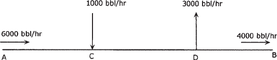
Figure 5.10.
Let us analyze the pressures required in a pipeline with injection and
delivery. The pipeline AB in Figure 5.10 shows 6000 bbl/hr entering the
pipeline at A. At a point C, a new stream of liquid enters the pipeline at a
rate of 1000 bbl/hr. Further along the pipeline, at point D, a volume of
3000 bbl/hr is stripped off the pipeline. Consequently, a resultant volume
of (6000+1000–3000) or 4000 bbl/hr is delivered to the pipeline terminus
at B. In order to calculate the pressures required at A for such a pipeline
with injection and deliveries we proceed as follows.
First, the pipe segment between A and C that has a uniform flow of
6000 bbl/hr is analyzed. The pressure drop in AC is calculated considering
the 6000 bbl/hr flow rate, pipe diameter, and liquid properties. Next the
pressure drop in the pipe segment CD with a flow rate of 7000 bbl/hr is
calculated taking into account the blended liquid properties by combining
the incoming stream at C (6000 bbl/hr) along the main line with the
injection stream (1000 bbl/hr) at C. Finally, the pressure drop in the pipe
segment DB is calculated considering a volume of 4000 bbl/hr and the
liquid properties in that segment, which would be the same as those of pipe
segment CD. The total frictional pressure drop between A and B will be the
sum of the three pressure drops calculated above. After adding any
elevation head between A and B and accounting for the required delivery
pressure at B we can calculate the total pressure required at point A for this
pipeline system. This is illustrated in the following example.
Figure 5.10 Injection and delivery.
Copyright © 2004 by Marcel Dekker, Inc.
Chapter 5100
Example Problem 5.5
In Figure 5.10 the pipeline from point A to point B is 48 miles long and is
18 in. in nominal diameter, with a 0.281 in. wall thickness. It is constructed
of 5LX-65 grade steel. At A, crude oil of specific gravity 0.85 and 10 cSt
viscosity enters the pipeline at a flow rate of 6000 bbl/hr. At C (milepost
22) a new stream of crude oil with a specific gravity of 0.82 and 3.5 cSt
viscosity enters the pipeline at a flow rate of 1000 bbl/hr. The mixed
stream then continues to point D (milepost 32) where 3000 bbl/hr is
stripped off the pipeline. The remaining volume continues to the end of the
pipeline at point B.
(a) Calculate the pressure required at A and the composition of the
crude oil arriving at terminus B at a minimum delivery pressure of
50 psi. Assume elevations at A, C, D, and B to be 100, 150, 250,
and 300 feet, respectively. Use the Colebrook-White equation
for pressure drop calculations and assume a pipe roughness of
0.002 in.
(b) How much pump HP will be required to maintain this flow rate at
A, assuming 50 psi pump suction pressure at A and 80% pump
efficiency?
(c) If a positive displacement (PD) pump is used to inject the stream at
C, what pressure and HP are required at C?
Solution
(a) The pressure drop due to friction for segment AC is calculated using
Equation (3.27) as follows:
Reynolds number=92.24×6000×24/(17.438×10)=76,170
Friction factor=0.02
Pressure drop=13.25psi/mile
Frictional pressure drop between A and C=13.25×22=291.5 psi
Next, we calculate the blended properties of the liquid stream after mixing
two streams at point C, by blending 6000 bbl/hr of crude A (specific
gravity of 0.85 and viscosity of 10 cSt) with 1000 bbl/hr of crude B
(specific gravity of 0.82 and viscosity of 3.5 cSt) using Equations (2.4) and
(2.21) as follows:
Blended specific gravity at C=0.8457
Blended viscosity at C=8.366 cSt
Copyright © 2004 by Marcel Dekker, Inc.
Pressure and Horsepower Required 101
For pipe segment CD we calculate the pressure drop by using above
properties at a flow rate of 7000 bbl/hr.
Reynolds number=92.24×7000×24/(17.438×8.366)=106,222
Friction factor=0.0188
Pressure drop=16.83 psi/mile
Frictional pressure drop between C and D=16.83×10=168.3 psi
Finally we calculate the pressure drop for pipe segment DB by using above
liquid properties at a flow rate of 4000 bbl/hr:
Reynolds number=92.24×4000×24/(17.438×8.366)=60,698
Friction factor=0.021
Pressure drop=6.13 psi/mile
Frictional pressure drop between D and B=6.13×16=98.08 psi
Therefore, the total frictional pressure drop between point A and point B is
291.5+168.3+98.08=557.9 psi
The elevation head between A and B consists of (150-100) ft between A
and C and (300-150) ft between C and B. We need to separate the total
elevation head in this fashion because of differences in liquid properties in
pipe segments AC and CB. Therefore, the total elevation head is
[(150-100)×0.85/2.31]+[(300-150)×0.8457/2.31]=73.32 psi
Adding the delivery pressure of 50 psi, the total pressure required at A is
therefore
557.9+73.32+50=681.22 psi
Therefore, the pressure required at A is 681.22 psi and the crude oil
arriving at terminus B has a specific gravity of 0.8457 and viscosity of
8.366 cSt.
(b) The HP required at A is calculated using Equation (5.16) as follows:
BHP=6000×(681.22-50)/(0.8×2449)=1933 HP
(c) To calculate the injection pump requirement at point C, we must first
calculate the pressure in the pipeline at point C that the PD pump has to
overcome.
Copyright © 2004 by Marcel Dekker, Inc.
Chapter 5102
The pressure at C is equal to the pressure at A minus the pressure drop
from A to C minus the elevation head from A to C:
P
C
=681.22-291.5-(150-100)×0.85/2.31=371.3 psi
The HP required for the PD pump at C is calculated using Equation (5.16)
as follows:
P
D
pump HP required=(371.3-50)×1000/(0.8×2449)=164
assuming 50 psi suction pressure and 80% pump efficiency.
5.10 Pipe Branches
In the previous section we discussed a pipeline with an injection point and
a delivery point between the pipeline inlet and pipeline terminus. These
injections and deliveries may actually consist of branch pipes bringing
liquid into the main line (incoming branch) and delivering liquid out of the
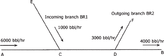
pipeline (outgoing branch). This is illustrated in Figure 5.11.
Sometimes we are interested in sizing the branch pipes for the required
flow rates and pressures. For example, in Figure 5.11 the incoming branch
BR1 needs to be sized to handle 1000 bbl/hr of liquid entering the pipeline
at point C with the specified pressure P
C
. We have to determine the
pressure required at the beginning of branch BR1 (point E) for a specified
branch pipe diameter, liquid properties, etc., so that the required pressure
P
C
is achieved at the end of the branch at point C.
Similarly, for an outgoing branch BR2 as shown in Figure 5.11, we are
interested in determining the branch pipe size such that the liquid stream
flowing through the outgoing branch arrives at its destination F with a
certain specified delivery pressure. We would use the starting pressure of
BR2 as P
D
, which represents the main line pressure at the junction with the
Figure 5.11 Incoming and outgoing branches.
Copyright © 2004 by Marcel Dekker, Inc.