Menon E.S. Liquid Pipeline Hydraulics
Подождите немного. Документ загружается.

Pressure and Horsepower Required 103
outgoing branch. Using the value of P
D
and the required delivery pressure
P
F
at F we can calculate the pressure drop per mile for BR2. Hence we can
select a pipe size to handle the flow rate through BR2. The following
example illustrates how branch pipes are sized for injection and deliveries.
Example Problem 5.6
(a) Using the data in Example Problem 5.5 and Figure 5.11, determine
the branch pipe sizes required for branch BR1 for the injection rate
of 1000 bbl/hr and an MAOP of 600 psi. Assume pipe branch BR1
to be 2.5 miles long and an essentially flat elevation profile.
(b) Calculate the pipe size for the outgoing branch BR2 to handle the
delivery of 3000 bbl/hr at D and pressure of 75 psi at F. The branch
BR2 is 4 miles long.
(c) What HP is required at beginning of branch BR1?
Solution
(a) Assume a 6 in. pipe for branch BR1 and calculate the pressure drop in
the 2.5 miles of pipe as follows: Using given liquid properties we
calculate:
Pressure drop=65.817 psi/mile for 1000 bbl/hr in a 6 in. pipe
Pressure required at E to match junction pressure of 371.3 at C is
P
E
=65.817×2.5+371.3=535.84 psi
Since this is less than the MAOP of 600 psi for BR1, a 6 in. line is
adequate.
(b) With a junction pressure of 166.39 psi available at D, a 10 in. pipe is
inadequate to carry 3000 bbl/hr of crude through the 4 miles of branch
pipe BR2 and provide a 75 psi delivery pressure at F. Next, assuming a 12
in. pipe for BR2, 3000 bbl/hr flow rate, specific gravity of 0.8457 and
viscosity of 8.366 cSt, we get
Pressure drop in BR2=20.07 psi/mile
Therefore, we get a delivery pressure of
P
F
=166.39-20.07×4=86.11 psi
which is higher than the minimum 50 psi delivery pressure required.
Therefore, branch pipe BR2 must be at least 12 in. nominal diameter.
Copyright © 2004 by Marcel Dekker, Inc.
Chapter 5104
(c) The HP required at beginning of branch BR1 is calculated to be as
follows using Equation (5.16):
HP=(535.84-550)×1000/(2449×0.8)=248
based on 80% efficiency and 50 psi suction pressure at E.
5.11 Pipe Loops
A pipe loop is a length of parallel pipe installed between two points on a
main pipeline as shown in Figure 5.12. We discussed parallel pipes and
equivalent diameter earlier in this chapter. In this section we will discuss
how looping an existing pipeline will reduce the pressure drop due to
friction and thus require less pumping HP.
The purpose of the pipe loop is to split the flow through a parallel
segment of the pipeline between the two locations, resulting in a reduced
pressure drop in that segment of the pipeline.
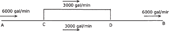
Consider pipeline from A to B with a loop installed from C to D as
shown in Figure 5.12. The flow rate between A and C is 6000 gal/min. At
C where the loop is installed the flow rate of 6000 gal/min is partially
diverted to the loop section with the remainder going through the mainline
portion CD. If we assume that the diameter of the loop is the same as that
of the main pipe, this will cause 3000 gal/min flow through the loop and an
equal amount through the mainline. Assume that the section CD of the
mainline prior to looping with the full flow of 6000 gal/min flowing
through it had a resulting pressure drop of 25 psi/mile. With the loop
installed, section CD has half the flow and therefore approximately one-
fourth of the pressure drop (since the pressure drop varies as the square of
the flow rate) or 6.25 psi/mile, based on Equation (3.27). If the length CD
is 10 miles, the total frictional pressure drop without the loop will be 250
psi. With the pipe loop the pressure drop will be 62.5 psi, which is a
significant reduction. Therefore if a pipeline section is bottlenecked due to
maximum allowable operating pressure, we can reduce the overall
pressure profile by installing a loop in that pipe segment.
To illustrate this concept further, consider the following example
problem.
Figure 5.12 Pipe loop.
Copyright © 2004 by Marcel Dekker, Inc.
Pressure and Horsepower Required 105
Example Problem 5.7
A 16 in. crude oil pipeline (0.250 in. wall thickness) is 30 miles long from
point A to point B. The flow rate at the inlet A is 4000 bbl/hr. The crude oil
properties are specific gravity of 0.85 and viscosity of 10 cSt at a flowing
temperature of 70° F.
(a) Calculate the pressure required at A without any pipe loop. Assume
50 psi delivery pressure at the terminus B and a flat pipeline
elevation profile.
(b) If a 10 mile portion CD, starting at milepost 10, is looped with an
identical 16 in. pipeline, calculate the reduced pressure at A.
(c) What is the difference in pump HP required at A between cases (a)
and (b) above? Assume 80% pump efficiency and 25 psi pump
suction pressure.
Solution
Using the Colebrook-White equation and assuming a pipe roughness of
0.002 in., we calculate the pressure drop per unit length using Equation
(3.27) as follows:
Reynolds number=92.24×4000×24/(15.5×10)=57,129
Friction factor f=0.0213
Pressure drop=11.28 psi/mile
(a) Therefore the total pressure required at A=30×11.28+50 = 388.40 psi
without any pipe loop. With 10 miles of pipe loop the flow rate through the
loop is 2000 bbl/hr and the revised pressure drop at the reduced flow is
calculated as
Pressure drop=3.28 psi/mile
The pressure drop in the 10 mile loop=10×3.28=32.8 psi
The pressure drop in the 10 mile section AC=10×11.28=112.8 psi
The pressure drop in the last 10 mile section DB=10×11.28=112.8 psi
Therefore
(b) Total pressure required at A=112.8+32.8+112.8+50= 308.40 psi
with the pipe loop.
Therefore, using the 10 mile loop causes a reduction of 80 psi in the
pressure required at point A.
(c) HP required without the loop is
HP=4000×(388.40-25)/(2449×0.8)=742
Copyright © 2004 by Marcel Dekker, Inc.
Chapter 5106
HP required considering the loop is
HP=4000×(308.40-25)/(2449×0.8)=579
Thus, installing the pipe loop results in a reduction in pumping HP of
(742–579)/742=22%
What would be the impact if the looped section of pipe were smaller
than the mainline? If we install a smaller pipe in parallel, the flow will still
be split through the loop section but will not be equally divided. The
smaller pipe will carry less flow rate than the larger mainline pipe, such
that the pressure drop through the mainline from point C to point D will
exactly equal the pressure drop through the pipe loop between C and D,
since both the mainline pipe and the pipe loop have common pressures at
the junction C and D.
To illustrate this, consider an 8 in. pipe looped with the 16 in. mainline.
Assume Q
8
represents the flow rate through the 8 in. loop and Q
16
the flow
rate through the 16 in. mainline portion. We can write
Q
8
+Q
16
=Total flow=4000 bbl/hr (5.21)
From Equation (3.27), we know that the frictional pressure drop in a pipe
is directly proportional to the square of the flow rate and inversely
proportional to the fifth power of the diameter. Therefore, we can write
Pressure drop in 8 in. pipe=K(Q
8
)
2
/(8.625-0.5)
5
considering 0.250 in. wall thickness and where K is a constant,
or
∆P
8
=K(Q
8
)
2
/35,409 (5.22)
Similarly, for the 16 in. pipe
∆P
16
=K(Q
16
)
2
/894,661 (5.23)
Dividing Equation (5.22) by Equation (5.23), we get
∆P
8
/∆P
16
=25.27(Q
8
/Q
16
)
2
Since ∆P
8
and ∆P
16
are equal in a loop system, the above equation reduces
to
Q
16
=5.03×Q
8
(5.24)
Solving Equation (5.21) and Equation (5.24) simultaneously, we get
Q
8
=4000/6.03=664 bbl/hr flow through the 8 in. loop
Copyright © 2004 by Marcel Dekker, Inc.
Pressure and Horsepower Required 107
and
Q
16
=4000-664=3336 bbl/hr flow through the
16 in. mainline portion
We can now calculate the pressure drop and the total pressure required at A
as we did in Example Problem 5.6 earlier.
Since the 10 mile looped portion of the 16 in. pipe has a flow rate of
3336 bbl/hr we calculate the pressure drop in this pipe first:
Reynolds number=92.24×3336×24/(15.5×10)=47,646
Friction factor f=0.0216
and
Pressure drop=7.96 psi/mile
Therefore, the pressure drop in the loop section
=7.96×10=79.6 psi
The pressure drops in section AC and section DB remain the same as
before. The total pressure required at A becomes
Pressure at A=112.8+79.6+112.8+50=355.2 psi
Compare this with 388.4 psi (without loop) and 308.4 psi (with 16 in.
loop).
We could also calculate the above using the equivalent-diameter
approach discussed earlier in this chapter. We will calculate the equivalent
diameter of a 10 mile pipe that will replace the 8 in./16 in. loop.
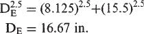
Recalling our discussions of parallel pipes and equivalent diameter in
Section 5.4 and using Equations (5.14) and (5.15), we calculate the
equivalent diameter D
E
as follows (after some simplifications):
Therefore, we can say that the two parallel pipes of diameters 8 in. and 16
in. together equal a single pipe of 16.67 in. internal diameter. To show that
the equivalent-diameter concept is fairly accurate, we will calculate the
pressure drop in this equivalent pipe and compare it with that for the two
parallel pipes.
Reynolds number=92.24×4000×24/(16.61×10)=53,120
Friction Factor f=0.0211
and
Pressure drop=7.77 psi/mile
Copyright © 2004 by Marcel Dekker, Inc.
Chapter 5108
Compare this with 7.96 psi/mile we calculated earlier. It can be seen that
the equivalent-diameter method is within 2% of the more exact method
and is therefore accurate for most practical purposes.
A practice problem with dissimilar pipe sizes as discussed above is
included at the end of this chapter as an exercise for the reader.
5.12 Summary
In this chapter we extended the pressure drop concept developed in
Chapter 3 to calculate the total pressure required to transport liquid
through a pipeline taking into account the elevation profile of the pipeline
and required delivery pressure at the terminus. We analyzed pipes in series
and parallel and introduced the concept of equivalent pipe length and
equivalent pipe diameter. System head curve calculations were discussed
to compare pressure required at various flow rates through a pipe segment.
Flow injection and delivery in pipelines were studied and the impact on the
hydraulic gradient discussed. We also sized branch piping connections and
discussed the advantage of looping a pipeline to reduce overall pressure
drop and pumping horsepower. For a given pipeline system, the hydraulic
horsepower, brake horsepower, and motor horsepower calculations were
illustrated using examples. A more comprehensive analysis of pumps and
HP required will be covered in Chapter 7.
5.13 Problems
5.13.1 A pipeline 50 miles long, 16 in. outside diameter, 0.250 in.
wall thickness is constructed of API 5LX-65 material. It is
used to transport diesel and other refined products from the
refinery at Carson to a storage tank at Compton. During phase
I, a flow rate of 5000 bbl/hr of diesel fuel is to be transported
with one pump station located at Carson. The required delivery
pressure at Compton is 50 psi. Assume a generally rolling
pipeline elevation profile without any critical peaks along the
pipeline. The elevation at Carson is 100 ft, and the storage tank
at Compton is located on top of a hill at an elevation of 350 ft.
(a) Using diesel with specific gravity of 0.85 and a viscosity
of 5.5 cSt at a flowing temperature of 70°F, calculate the
total pressure required at Carson to transport 5000 bbl/hr
of diesel on a continuous basis. Use the Hazen-Williams
equation with a C-factor of 125. The Carson pump
Copyright © 2004 by Marcel Dekker, Inc.
Pressure and Horsepower Required 109
suction pressure is 30 psi and the pump is driven by a
constant-speed electric motor.
(b) Determine the BHP and motor HP required at Carson
assuming 82% pump efficiency and 96% motor
efficiency.
(c) What size electric motor would be required at Carson?
(d) Assuming a maximum allowable operating pressure of
1400 psi for the pipeline, how much additional
throughput can be achieved in phase II if the pumps are
modified at Carson?
5.13.2 A water pipeline is being built to transport 2300 m
3
/hr from a
storage tank at Lyon (elevation 500m) to a distribution facility
50 km away at Fenner (elevation 850 m). What size pipe will
be required to limit velocities to 3 m/s and allowable pipeline
pressure of 5.5MPa? No intermediate pump stations are to be
used. Delivery pressure at Fenner is 0.3 MPa. Use the Hazen-
Williams equation with a C-factor of 110.
5.13.3 In Problem 5.13.1, what throughputs can be achieved when
pumping gasoline alone? Use a specific gravity of 0.74 and
viscosity of 0.65 for gasoline at the flowing temperature.
Compare the pump head requirements when pumping diesel
versus gasoline. Use the Hazen-Williams equation with a C-
factor of 145.
5.13.4 Calculate the BHP requirements for the above problem for
both diesel and gasoline movements.
5.13.5 Consider a loop pipeline similar to that in Example Problem
5.7. Instead of the loop being 16 in. consider a smaller 10 in.
pipe installed in parallel for the middle 10 mile section. How
does the pressure at A change compared with the no-loop
case?
Copyright © 2004 by Marcel Dekker, Inc.
110
6
Multi-Pump Station Pipelines
In Chapter 5 we calculated the total pressure required to pump a liquid
through a pipeline from point A to point B at a specified flow rate. Three
components of the total pressure required (friction head, elevation head,
and delivery pressure) were analyzed. Depending on the maximum
allowable operating pressure (MAOP) of the pipeline we concluded that
one or more pump stations may be required to handle the throughput.
In this chapter we will discuss pipeline hydraulics for multiple pump
stations. Hydraulic balance and how to determine the intermediate booster
pump stations will be explained. To utilize pipe material efficiently we will
explore telescoping pipe wall thickness and grade tapering. Also covered will
be slack line flow and a more detailed analysis of batched pipeline hydraulics.
6.1 Hydraulic Balance and Pump Stations Required
Suppose calculations indicate that at a flow rate of 5000 gal/min, a 100 mile
pipeline requires a pressure of 2000 psi at the beginning of the pipeline. This
2000 psi pressure may be provided in two steps of 1000 psi each or three
steps of approximately 670 psi each. In fact, due to the internal pressure limit
of the pipe, we may not be able to provide one pump station at the beginning
of the pipeline, operating at 2000 psi. Most pipelines have an internal
Copyright © 2004 by Marcel Dekker, Inc.
Multi-Pump Station Pipelines 111
pressure limit of 1000 to 1440 psi based on pipe wall thickness, grade of
steel, etc., as we found in Chapter 4. Therefore, in long pipelines the total
pressure required to pump the liquid is provided in two or more stages by
installing intermediate booster pumps along the pipeline.
In the example case with a 2000 psi requirement and 1400 psi pipeline
MAOP, we would provide this pressure as follows. The pump station at the
start of the pipeline will provide a discharge pressure of 1000 psi, which
will be consumed by friction loss in the pipeline and at some point
(roughly halfway) along the pipeline the pressure will drop to zero. At this
location we boost the liquid pressure to 1000 psi using an intermediate
booster pump station. We have assumed that the pipeline is essentially on
a flat elevation profile.
This pressure of 1000 psi will be sufficient to take care of the friction
loss in the second half of the pipeline length. The liquid pressure will
reduce to zero at the end of the pipeline. Since the liquid pressure at any
point along the pipeline must be above the vapor pressure of the liquid at
the flowing temperature, and the intermediate pumps require certain
minimum suction pressure, we cannot allow the pressure at any point to
drop to zero. Accordingly, we will locate the second pump station at a
point where the pressure has dropped to a suitable suction pressure, such
as 50 psi. The minimum suction pressure required is also dictated by the
particular pump and may have to be higher than 50 psi, to account for any
restrictions and suction piping losses at the pump station. For the present,
we will assume 50 psi suction pressure is adequate for each pump station.
Hence, starting with a discharge pressure of 1050 psi (1000+50) we will
locate the second pump station (intermediate booster pump) along the
pipeline where the pressure has dropped to 50 psi. This pump station will
then boost the liquid pressure back up to 1050 psi and will deliver the
liquid to the pipeline terminus at 50 psi. Thus each pump station provides
1000 psi differential pressure (discharge pressure minus suction pressure)
to the liquid, together matching the total pressure requirement of 2000 psi
at 5000 gal/min flow rate.
Note that in the above analysis we ignored pipeline elevations and
assumed that the pipeline profile is essentially flat. With elevations taken
into account, the location of the intermediate booster pump will be
different from that of a pipeline along a flat terrain.
Hydraulic balance is when each pump station supplies the same
amount of energy to the liquid. Ideally pump stations will be located at
hydraulic centers. This will result in the same horsepower (HP) being
added to the liquid at each pump station. For a single flow rate at the inlet
of the pipeline (no intermediate injections or deliveries), the hydraulic
centers will also result in the same discharge pressures at each pump
Copyright © 2004 by Marcel Dekker, Inc.
Chapter 6112
station. Due to topographic conditions it may not be possible to locate
the intermediate pump station at the locations desired for hydraulic
balance. For example, calculations may show that three pump stations
are required to handle the flow rate and that the two intermediate pump
stations are to be located at milepost 50 and milepost 85. The location of
milepost 50, when investigated in the field, may be found to be in the
middle of a swamp or a river. Hence we will have to relocate the pump
station to a more suitable location after field investigation. If the revised
location of the second pump station were at milepost 52, then obviously
hydraulic balance would no longer be valid. Recalculations of the
hydraulics with the newly selected pump station locations will show
hydraulic imbalance and all pump stations will not be operating at the
same discharge pressure or providing the same amount of HP to the
liquid at each pump station. However, while it is desirable to have all
pump stations balanced, it may not be practical. Balanced pump station
locations afford the advantage of using identical pumps and motors and
the convenience of maintaining a common set of spare parts (pump
rotating elements, mechanical seal, etc.) at a central operating district
location.
In Chapter 5 we discussed how the location of an intermediate pump
station can be calculated from given data on pump station suction pressure,
discharge pressure, etc. In Section 5.2 we presented a formula to calculate
the discharge pressure for a pipeline system with two pump stations given
the total pressure required for a particular flow rate. We will expand on that
discussion by presenting a method to calculate the pump station pressures
for hydraulic balance.
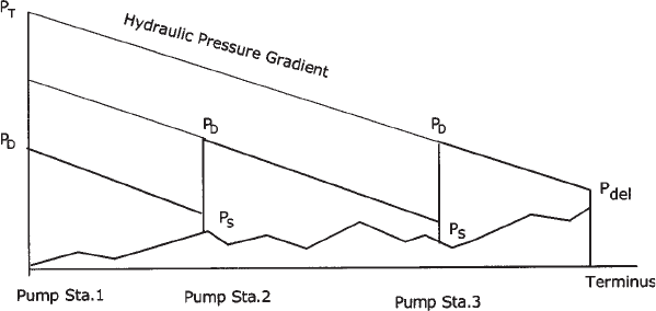
Figure 6.1 shows a pipeline with varying elevation profile but no
significant controlling peaks along the pipeline. The total pressure P
T
was
Figure 6.1 Hydraulic gradient: multiple pump stations.
Copyright © 2004 by Marcel Dekker, Inc.