Moulson A.J., Herbert J.M. Electroceramics: Materials, Properties, Applications
Подождите немного. Документ загружается.


be assumed that the difference between the temperature T of the resistor and the
temperature T
0
of its surroundings is proportional to the power being dissipated,
i.e.
T T
0
¼ k
th
UI ¼ k
th
P ð4:12Þ
where P is the power, U is the voltage drop across the thermistor, I is the current
and k
th
is a constant depending on the mounting, shape and surface finish of the
thermistor as well as the ambient conditions. Because the power dissipated is
proportional to 1=k
th
, this can be regarded as a ‘dissipation factor’. Evidently k
th
can vary between wide limits, but the following example from experiment gives
the order of magnitude involved. Small rods 5–50 mm long and 3–10 mm in
diameter with copper leads about 10 mm long and 0.5–2 mm in diameter
mounted in air have a heat dissipation per degree Celsius excess over that of the
ambient given by
1=k
th
¼ g
1
A þ g
2
d
2
ð4:13Þ
where A is the surface area and d is the lead diameter. If A is in square
millimetres and d is in millimetres, g
1
0:04 and g
2
10. As indicated by
Eq. (4.13), when the thermistors are very small the heat dissipation is governed
by conduction down the leads rather than by convection currents in the
surrounding air, which have the dominating influence in the case of larger units.
Substituting Eq. (4.12) into Eq. (4.10) and referring to the resistance of the
device rather than to the resistivity of the material gives
RðTÞ¼R
1
exp
B
T
0
þ k
th
P
ð4:14Þ
RðTÞ can be calculated as a function of P from Eq. (4.14); U and I can then be
derived from the relations
U
2
¼ PRðTÞ
I
2
¼ P=RðTÞ
ð4:15Þ
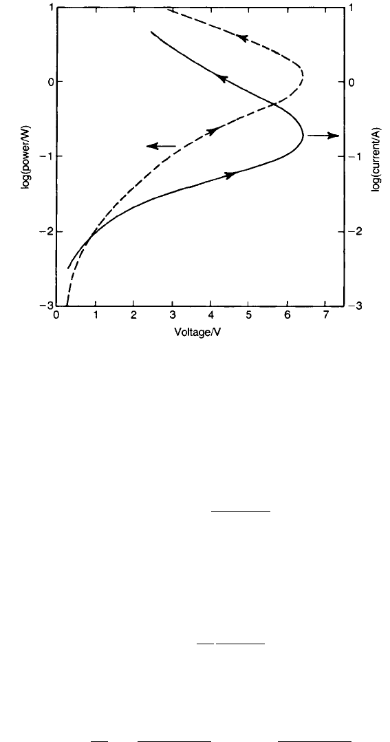
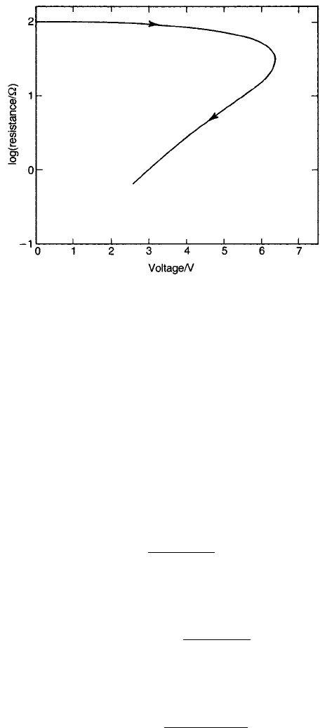
P and I are shown as functions of U in Fig. 4.16 and R is shown as a
function of U in Fig. 4.17. The curves represent equilibrium conditions, and it
is evident that no equilibrium can exist above a certain maintained maximum
voltage. If a higher maintained voltage is applied, the current will go on rising
indefinitely until the accompanying high temperature destroys the unit. In
practice there must always be a temperature-insensitive resistor in series with
a thermistor if sufficient power to raise its temperature appreciably is to be
applied.
162 CERAMIC CONDUCTORS
TEAMFLY
Team-Fly
®
The maximum voltage that can be applied to a thermistor, without a runaway
condition being established, can be calculated from the voltage–power relation
obtained by substituting Eq. (4.14) into Eq. (4.15):
U ¼ P
1=2
R
1
exp
B
T
0
þ k
th
P
1=2
ð4:16Þ
The power PðU
max
Þ corresponding to the maximum voltage U
max
that can be
maintained across the thermistor without runaway occurring can be found by
differentiating Eq. (4.16) and putting dU=dP ¼ 0. Under the condition that
4T
2
0
=ðB 2T
0
Þ
2
<< 1,
PðU
max
Þ¼
1
k
th
T
2
0
B 2T
0
ð4:17Þ
The corresponding expression for U
max
can be found by substituting PðU
max
Þ
from Eq. (4.17) into Eq. (4.16) to give
U
max
¼
1
k
th
1=2
T
0
ðB 2T
0
Þ
1=2
R
1=2
1
exp
BðB 2T
0
Þ
2T
0
ðB T
0
Þ
ð4:18Þ
TEMPERATURE-SENSITIVE RESISTORS 163
Fig. 4.16 Power and current versus voltage for an NTC thermistor with R
1
¼ 4:54 10
3
O,
B ¼ 3000 K, T
0
¼ 300 K and T T
0
¼ 30P K.
It is apparent that U
max
increases with the ability of the thermistor to dissipate
heat (proportional to 1=k
th
). Also, because the exponential term dominates, U
max
decreases as T
0
increases, as expected.
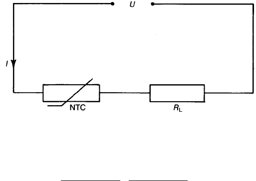
Some of the properties and uses of thermistors, other than temperature
sensing, can be appreciated from the simple circuit shown in Fig. 4.18. A fixed
voltage U is applied to an NTC thermistor of resistance RðTÞ in series with a load
resistance R
L
which is invariant with temperature. In this case there is the
complication that, as the thermistor warms up and falls in resistance, the voltage
across it also falls. The situation is analysed as follows:
I ¼
U
RðTÞþR
L
ð4:19Þ
and the voltage U
th
across the thermistor is
U
th
¼ RðTÞI ¼
URðTÞ
RðTÞþR
L
ð4:20Þ
The power P dissipated in the thermistor is
P ¼ IU
th
¼
U
2
RðTÞ
fRðTÞþR
L
g
2
ð4:21Þ
Eliminating P between Eqs (4.14) and (4.21) and rearranging yields
164 CERAMIC CONDUCTORS
Fig. 4.17 Resistance versus voltage under the same conditions as in Fig. 4.16.
U
2
¼
fRðTÞþR
L
g
2
k
th
RðTÞ
B
lnfRðTÞ=R
1
g
T
0
ð4:22Þ
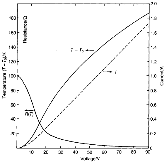
Eq. (4.22) can be used to plot the relationship between U and RðTÞ for given
values of the other parameters. The relationship for B ¼ 3000 K, T
0
¼ 300 K,
R
1
¼ 4:54 10
3
O, R
L
¼ 50 O and k
th
¼ 30 K W
1
is shown in Fig. 4.19 as an
example. The current I (Eq. (4.19)) and the temperature of the thermistor
calculated from Eqs (4.21) and (4.12) are also shown. It can be seen from the
figure that, for U ¼ 50 V, RðTÞ5 O and I 0:9 A and, when temperature
equilibrium has been established, T T
0
¼ 127 K (T ¼ 154 8C).
The room temperature resistance Rð300Þ of the thermistor, calculated from the
equivalent to Eq. (4.10) and using R
1
¼ 4:54 10
3
O, is 100 O so that
immediately the switch is closed and before the temperature of the thermistor
has changed the current is 0.33 A and the power dissipated in the load is 5.4 W.
After the thermistor has reached temperature equilibrium with its surroundings,
the current rises to 0.9 A and power dissipation in the load rises to 40 W. Thus a
thermistor can be used to delay the development of full power in a load during
the period it takes to reach its final temperature. The penalty is the power
required to maintain the thermistor at temperature, in this case about 4 W. Using
a thermistor with a higher TCR, i.e. a higher B value, would not greatly affect the
ratio of the power in the load when first switched on to that at equilibrium, but it
would decrease the power wasted in the thermistor, provided that RðT
0
Þ is the
same in both instances.
A further consideration in the use of NTC resistors arises from the distribution
of temperature within them. Clearly the inner part of the resistor must be hotter
than the surface region in order to maintain an outward heat flow, but, in
addition, the negative coefficient of resistivity will result in the inner part having
a lower resistance and a higher current passing through it, so that the
temperature gradient between the inner and outer parts will be enhanced. If
the thermistor is grossly overloaded, the results can be catastrophic; for instance,
TEMPERATURE-SENSITIVE RESISTORS 165
Fig. 4.18 NTC thermistor with a series load.
the central core of a rod-shaped NTC resistor may melt. In practical cases a
severe mechanical stress can arise from the temperature gradient and may result
in fracture or the development of internal cracks. Thermal stress due to
differences in thermal expansion coefficients may also cause the metallization to
separate from the ceramic. The probability of thermal stress failure depends on
the same thermal and mechanical properties as thermal shock failure, which is
discussed in Section 5.3.
At low power levels NTC thermistors are widely used wherever temperature
needs to be controlled or accurately measured, for example in automotive
engines, air-conditioning units, hair dryers, and in the medical field for heart
catheters, fever thermometers, etc. They are also used to maintain picture
stability in television receivers by compensating for increases in the resistance of
the beam-focusing coils as temperature rises in the cabinet. The dependence of
resistance on the rate of heat dissipation enables them to be used as indicators
that fuel tanks are filled to a prescribed level and also in instruments for the
measurement of the velocity of fluids.
Examples of NTC thermistors are shown in Fig. 4.15.
166 CERAMIC CONDUCTORS
Fig. 4.19 Resistance, current and temperature versus voltage for an NTC thermistor with
series load: P ¼ðT T
0
Þ=30 W.
4.4.2 Positive temperature coe⁄cient resistors
(PTC thermistors)
PTC resistors could be classified as critical temperature resistors because, in the
case of the most widely used type, the positive coefficient is associated with the
ferroelectric Curie point.
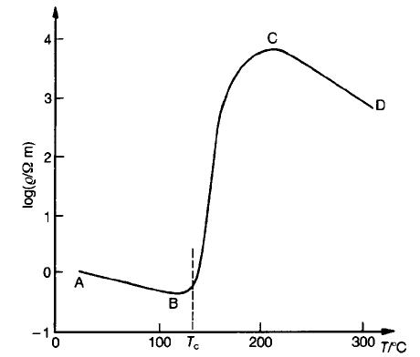
A typical PTC characteristic is shown in Fig. 4.20. In the instance illustrated
the material has the negative resistivity–temperature characteristic associated
with normal semiconductors up to about 100 8C (AB) and above about 200 8C
(CD), while between these temperatures (BC) there is an increase of several
orders of magnitude in resistivity. The underlying physics of the effect as outlined
below draws on the discussions in Sections 2.6.2 and 2.7.3.
The PTC effect is exhibited by specially doped and processed BaTiO
3
. Because
the effect is not observed in the single-crystal form of the material its cause must
be assumed to lie in processes associated with grain boundaries. Attention here is
focused on lanthanum-doped BaTiO
3
(BLT), although other donor dopants
would be satisfactory, e.g. yttrium (A site) or niobium, tantalum or antimony (B
site).
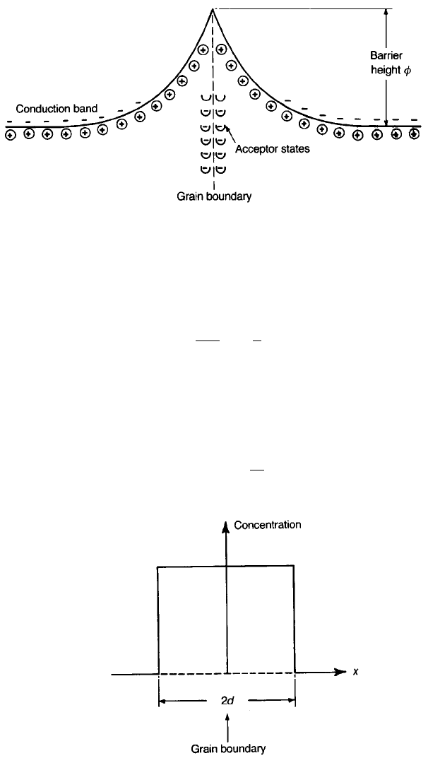
Electron acceptor states in the grain boundary together with nearby ionized
donor states give rise to an electrical double layer, as shown in Fig. 4.21. In
consequence, conduction band electrons moving up to a grain boundary from
the interior of a grain are confronted by a potential barrier of height f.To
obtain an expression for f the simplifying assumption is made that the positive
charge density is constant out to a distance d from the grain boundary, where it
falls to zero, as shown in Fig. 4.22. It is also assumed that the potential varies
TEMPERATURE-SENSITIVE RESISTORS 167
Fig. 4.20 Typical characteristic of PTC thermistor material.
only with the distance x from the grain boundary. The barrier height is found by
first integrating the one-dimensional form of Poisson’s equation
d
2
V
dx
2
¼
r
e
ð4:23Þ
in which V and r are respectively the electrostatic potential and the charge
density at x and e is the permittivity. If the boundary condition E ¼dV=dx ¼ 0
at x ¼ d is assumed and V ¼ 0 is arbitrarily fixed at x ¼ 0, the potential V
d
at
x ¼ d is given by
V
d
¼r
d
2
2e
ð4:24Þ
168 CERAMIC CONDUCTORS
Fig. 4.21 Electrical double layer at a grain boundary.
Fig. 4.22 Assumed positive charge density distribution in the vicinity of a grain boundary.
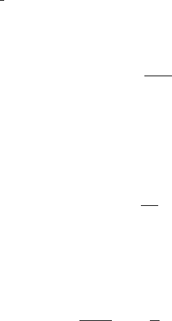
From Fig. 4.22 rd ¼
1
2
N
s
jej where N
s
is the surface density of acceptor states near
the grain boundary and jej is the magnitude of the electronic charge. Therefore
the height f of the barrier to an electron becomes
f ¼eV
d
¼
e
2
N
2
s
8en
ð4:25Þ
where n ¼ r=jej is the volume density of donor states in the grain.
The probability that electrons are able to surmount the barrier is measured by
the Boltzmann factor expðf=kTÞ, leading to the following proportionality for
the resistance R
gb
of a grain boundary:
R
gb
/ exp
f
kT
ð4:26Þ
Because BLT is ferroelectric, above its Curie temperature e ¼ C=ðT yÞ (see
Eq. (2.90)), where C is the Curie constant and y is the Curie–Weiss temperature.
Therefore
R
gb
/ exp
e
2
N
2
s
8nkC
1
y
T
T > y ð4:27Þ
The PTC effect is seen to have its origins in the resistance of the grain boundary
region which increases exponentially with temperature above the ferroelectric–
paraelectric transition temperature. It therefore depends on the number of grain
boundaries per unit volume of ceramic, i.e. on the microstructure, and of course
on the acceptor and donor state densities N
s
and n.
It is evident that the double layers at the grain boundaries constitute Schottky
barriers which are similar in some respects to those formed in VDR resistors. In
accord with this it is found that the resistivity–temperature relation of PTC
material is voltage sensitive. The low-temperature resistivity may be reduced by a
factor of 4 by an increase in applied field from 1 to 80 kV m
1
, and the ratio of
maximum to minimum resistivities, above and below T
c
, may be reduced from
five to three orders of magnitude.
Because the PTC effect is partly a consequence of the steeply falling
permittivity just above the ferroelectric transition temperature, why does the
resistance not similarly increase with a strongly decreasing permittivity as
temperature falls below the Curie temperature? Below T
c
the material is
ferroelectric with each grain comprising domains terminating on grain
boundaries. A discontinuity in polarization at the grain boundary necessitates
a polarization charge at the grain boundary whose sign depends upon the nature
of the discontinuity. This surface charge partially cancels the double-layer effect
and removes, or at least reduces, the barrier in places. The barriers throughout a
polycrystalline ceramic may be short circuited by such a process so that the
material as a whole has low resistivity. The effect will depend upon details of the
TEMPERATURE-SENSITIVE RESISTORS 169
domain configuration, the magnitude of the polarization and the density of
surface acceptor states. The lack of precise information about these precludes the
possibility of predicting electrical properties in this temperature region.
In its essentials the model serves as a sound basis for understanding the PTC
effect, but little is known regarding the nature of the acceptor states. It has been
proposed that they arise because the ceramic does not achieve thermodynamic
equilibrium during processing. On this basis a somewhat speculative mechanism
for the formation of acceptors is outlined below.
At the sintering temperature the excess charge of La
.
Ba
is largely compensated
by the promotion of electrons into the conduction band (see Eq. (2.57)). On
cooling, some of the electrons are replaced by V
0000
Ti
(see Eq. (2.59)):
4TiO
2
þ O
2
ðgÞþ4e
0
Ð 3Ti
Ti
þ V
0000
Ti
þ 8O
O
þ ‘TiO
2
’ ð4:28Þ
It can be seen from Eq. (4.28) that the interchange of electrons and vacant cation
sites requires the presence of oxygen gas and the formation of TiO
2
in a phase
separate from that of BaTiO
3
. Oxygen is available at the surface of the grains
through diffusion along the grain boundaries. The extension of the reaction to
the interior of a grain requires the diffusion of oxygen ions through the crystal
lattice, which is a much slower process than grain boundary diffusion, especially
as the concentration of oxygen vacancies is minimal in the presence of donor ions
(Fig. 2.13). Therefore it is possible that, on rapid cooling to room temperature,
V
0000
Ti
will be at a higher concentration in the surface layers of the grains where they
will act as the acceptors postulated in Fig. 4.21. The ‘TiO
2
’ may form part of an
intergranular phase based on Ba
6
Ti
17
O
40
(see Fig. 5.41) which would require the
diffusion of V
0000
Ti
into the bulk of the grains, but it is unlikely that such a highly
charged entity would be particularly mobile, so providing a further reason for a
higher V
0000
Ti
concentration at the grain surface. It has been found empirically that
PTC properties are improved when the acceptor ion Mn
0
Ti
is present (at about the
0.05 cat.% level) in the intergranular region. The overall increase in resistivity
during the transition is made larger and the resistivity at lower temperatures is
reduced.
The PTC effect is distinguished from the majority of other critical temperature
effects in the ease with which the critical temperature can be shifted by altering
the composition. The replacement of barium in BaTiO
3
by strontium lowers the
critical temperature by 4 8C per percentage atomic replacement, whilst
replacement by lead raises the critical temperature by 4.3 8C per percentage
atomic replacement (see Fig. 2.47). Since the critical temperature for BaTiO
3
is
120–130 8C, it is a simple matter to prepare ceramics with PTC regions anywhere
between 100 8C and þ250 8C, although the highest temperature coefficients are
found in barium titanate compositions without major quantities of substituents.
The fabrication route for PTC thermistors is typical of that employed for
modern electroceramics except in so far as special attention is given to
maintaining high purity and to the firing schedule.
170 CERAMIC CONDUCTORS
The basic composition is usually derived from oxides or carbonates, e.g.
BaCO
3
, SrCO
3
, TiO
2
,La
2
O
3
etc., which are mixed in a polyethylene-lined ball-
mill using mullite or agate balls and deionized water. Alternatively, and if
economically viable, the mix can be synthesized from organometallic
compounds, usually in conjunction with soluble inorganic salts.
The mix is dried and calcined (1000 8C) when the semiconducting ceramic
is formed. The calcine is ball-milled, in a similar mill to that used before, to a
size of about 1 mm. At this stage other dopants and binders can be added, e.g.
MnSO
4
and polyvinyl alcohol, or the mix might be blended with PbTiO
3
if
the device is to have a high switching temperature; the special treatment given to
the lead compound is necessary because of the high volatility of PbO. The slurry
is then granulated, usually by spray drying, when it is ready for pressing into
discs.
Sintering at about 1350 8C in air and the subsequent cooling stages have to be
carefully controlled since this is when the barrier-layer characteristics are
established. The conditions must be such as to allow a barrier layer of optimum
thickness (0.1–1 mm) to form, while the grains grow, ideally uniformly, to the
optimum size, normally about 50 mm.
After the sintering stage, electrodes are applied, usually either by electroless
nickel plating or by painting or screening on specially adapted silver paint. Leads
are then soldered to the electrodes when, for many applications, the device is
complete; in other cases it may be encapsulated in epoxy or silicone resins.
Examples are illustrated in Fig. 4.15.
A typical current–voltage relation for a PTC body in thermal equilibrium is
shown in Fig. 4.23. At low voltages (EF) the relation is approximately ohmic
(Fig. 4.20, AB); then, as the temperature of the thermistor reaches the regime of
steeply rising resistance (Fig. 4.20, BC), its temperature rises only slowly with
increasing voltage and the current falls to give a correspondingly slow increase in
power dissipation. If the increase in voltage is sufficient to bring the temperature
above the region of rising resistance (Fig. 4.20, CD), the temperature coefficient
becomes negative and a rapid increase in current and temperature results.
If the rate of heat dissipation from the thermistor is changed, the location of
FG in Fig. 4.23 will shift. The temperature of the element changes only slightly,
but the power changes to a level corresponding to the new rate of heat
dissipation. If the voltage is kept constant the current becomes a measure of the
rate of heat dissipation, and this relation is used in a number of devices to sense a
change in environment. There is a marked change in heat dissipation when a
probe at thermal equilibrium in air is plunged into a liquid at the same
temperature as the air. Devices for indicating the level of liquids in tanks are
based on this change.
The relative constancy in the temperature of a PTC device, despite changes in
both the voltage supply and ambient conditions, when it is maintained on the
steeply rising limb of its resistance–temperature characteristic has led to its use as
TEMPERATURE-SENSITIVE RESISTORS 171