Moulson A.J., Herbert J.M. Electroceramics: Materials, Properties, Applications
Подождите немного. Документ загружается.

coincides with the polarization. The effective negative birefringence is specified
by
Dn, the magnitude of which depends on the applied field strength E.
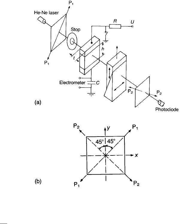
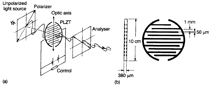
The birefringence is measured using apparatus of the type shown in
Fig. 8.10(a). He–Ne laser light (l ¼ 0.633 mm) is passed through the polarizer
P
1
and then through the electroded specimen. The specimen is in the form of a
polished plate, of thickness t typically 250 mm, carrying gold electrodes with a
gap of approximately 1 mm.
With no voltage applied to the electrodes an unpoled specimen is in the
isotropic state and the light is passed on unchanged to the second polarizer P
2
where it is extinguished, as measured by the photodiode. Any field-induced
relative retardation G between the horizontal and vertical components of the
plane light that takes place during passage through the specimen leads to
ellipticity and so a part of the light is transmitted by P
2
.
The Babinet compensator is a calibrated optical device comprising two wedge-
shaped pieces of quartz arranged so that their optic axes, and the light path, are
452 ELECTRO-OPTIC CERAMICS
Fig. 8.10 (a) Optical system for measuring the electro-optic coefficient; (b) reference planes
viewed along the optical axis from the photodiode.
TEAMFLY
Team-Fly
®

mutually perpendicular. By moving one wedge relative to the other in the sense
indicated, variable and known amounts of relative retardation can be introduced
between the vertical and horizontal components of the plane-polarized light.
Therefore the relative retardation introduced by the specimen can be measured
directly from the adjustment of the calibrated compensator necessary to return
the situation to complete extinction. It follows that
G ¼
D nt ¼
1
2
n
3
r
c
Et ¼
1
2
n
3
r
c
U
h
t ð8:44Þ
For h ¼ t and G ¼ l=2, U ¼ V
p
¼l=n
3
r
c
, i.e. the half-wave voltage referred to
in Section 8.1.3 and Table 8.1.
An expression is now derived for the light intensity transmitted by P
2
in the
case where the relative retardation introduced by the specimen is G and the
compensator is removed. It is helpful to refer to Fig. 8.10(b) which represents
the system viewed from the photodiode. If the amplitude transmitted by the
polarizer P
1
is a sin(ot), then the x and y components incident on the PLZT are
x ¼
a
p
2
sinðotÞð8:45Þ
y ¼
a
p
2
sinðotÞð8:46Þ
On passing through the uniaxial negative PLZT the x component is retarded by
an angle d ¼ðG=lÞ2p, where G ¼ t
Dn. The amplitude a
T
transmitted by P
2
is
a
T
¼ y cos 45
x cos 45
¼
1
p
2
ðy xÞ
i.e.
a
T
¼
a
2
fsinðotÞsinðot dÞg
which reduces to
a
T
¼ a sin
d
2
cos
ot
d
2
ð8:47Þ
The time-averaged transmitted intensity I
T
is given by
I
T
¼ a
2
sin
2
d
2
cos
2
ot
d
2
i.e.
LANTHANUM-SUBSTITUTED LEAD ZIRCONATE TITANATE 453

I
T
¼
a
2
2
sin
2
d
2
¼
1
4
I
0
sin
2
Gp
l
ð8:48Þ
where I
0
is the intensity incident on P
1
. I
T
is a maximum when G ¼(2m+1)
l=2, d ¼ð2m þ 1Þp and a minimum when G ¼ mlðd ¼ 2mpÞ, where m is an
integer.
The total polarization in the specimen for a given applied field can be
measured by the voltage developed across the series capacitor, because
capacitors in series each carry the same charge. Closing the switch discharges
the specimen and capacitor; opening it charges the specimen to a voltage close to
U, provided that C is very much greater (at least a factor of 10
3
) than the
specimen capacitance. This allows the determination of hysteresis loops
corresponding to the birefringence–field or birefringence–polarization relations.
8.2.3 Electro-optic characteristics
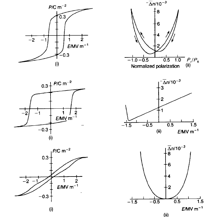
Depending on composition PLZT ceramics display one of three major types of
electro-optic characteristic, i.e. ‘memory’, ‘linear’ or ‘quadratic’. These are shown
in Fig. 8.11, together with the corresponding hysteresis loops, and are discussed
briefly below.
Memory
A typical PLZT exhibiting memory characteristics has the composition 8/65/35
and a grain size of about 2 mm. The general approach to obtaining a hysteresis
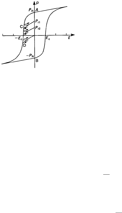
loop is referred to above; the intermediate remanent polarization states (e.g. P
r1
etc. in Fig. 8.12) necessary to generate the Dn versus normalized polarization
plots (Fig. 8.11(a)(ii)) are obtained as follows.
The polarization is saturated by applying a field of approximately 3E
c
, where
E
c
is the coercive field. When the saturating field is removed, the polarization
relaxes to the remanent states P
R
or P
R
. Intermediate remanent states, such as
P
r1
, can be achieved by removing the field after bringing the electrical state of the
material to C, applying an appropriate voltage for a limited time and controlling
the charge movement by means of a high series resistance. There is a state D on
Fig. 8.12 from which the polarization relaxes to zero. Intermediate states can be
reached equally well from the positive E quadrants, and the right-hand side of
Fig. 8.11(a)(ii) reflects the observed hysteresis between the two approaches. To
achieve zero birefringence, coupled with zero polarization, it is usually necessary
to depole a specimen thermally. Thermal depoling involves heating the specimen
above the Curie temperature and cooling in the absence of a field, a procedure
which randomizes the domain configuration.
454 ELECTRO-OPTIC CERAMICS
The reduced polarization states P
r1
, P
r2
etc. are due partly to 1808 domain
reversals, which do not affect the birefringence, and partly to changes in other
domains (718 and 1098 in rhombohedral crystals) which reduce both the
polarization and the birefringence. The relation between birefringence and
remanent polarization is therefore complex and, as indicated in Fig. 8.11, zero
remanent polarization does not necessarily correspond to zero birefringence.
The existence of intermediate polarization states is not of great practical use
because the effect of an applied field depends on both its exact mode of
application and the previous treatment of a specimen. Reproducible results can
be achieved by having an electrode and circuit arrangement that allows the
LANTHANUM-SUBSTITUTED LEAD ZIRCONATE TITANATE 455
(c) Quadratic
(b) Linear
(a) Memory
Fig. 8.11 Hysteresis and electro-optic characteristics of the three main types of PLZT: (a)
memory; (b) linear; (c) quadratic (after G.H. Haertling (1971) J. Am. Ceram. Soc., 54, 303).
application of fields in two approximately perpendicular directions. This permits
the establishment of two optically distinct states by applying brief pulses to the
electrodes. These states are stable in the absence of an external field.
Linear
Compositions that exhibit the linear electro-optic effect (Pockels effect) tend to
come from the PbTiO
3
-rich end of the solid solution range (Fig. 8.8). As
expected, high PbTiO
3
favours tetragonal distortion from the cubic; for example,
for 8/60/40 c=a ¼ 1.002, whereas for 8/40/60 c=a ¼ 1.01. A consequence of high
tetragonality is high coercivity.
To exhibit the Pockels effect, the ceramic, e.g. 8/40/60, is first poled to positive
saturation remanence P
R
with a field of approximately 3 MV m
71
, i.e. about
twice the coercive field (cf. the left-hand side of Fig. 8.11(b)(i)).
Dn is then
measured, at remanence, for positive and negative d.c. fields ranging from
71.4 MV m
71
to 2.0 MV m
71
. Over this range linearity is excellent (right-hand
side of Fig. 8.11(b)(ii)) with a Pockels coefficient r
c
of approximately 100 pm V
71
(Table 8.1). Some PLZT compositions have higher r
c
values, e.g. 8/65/35
(Table 8.1), but at the expense of departures from linearity for small fields. Grain
size is known to have a very significant effect on the linearity of the
Dn–E
characteristic.
Quadratic
Compositions that display the quadratic Kerr effect lie close to the ferroelectric
rhombohedral–tetragonal boundary (Fig. 8.8); 9.5/65/35 is typical. At room
temperature they are essentially cubic, but the application of a field enforces a
transition to the rhombohedral or tetragonal ferroelectric phase, and the optical
456 ELECTRO-OPTIC CERAMICS
Fig. 8.12 Establishment of intermediate polarization states P
r1
, P
r2
etc.
anisotropy increases with E
2
. Because of their zero, or very low, remanence
values, they are known as ‘slim-loop’ materials (left-hand side of Fig. 8.11(c)(i)).
Longitudinal effects
Strain bias
In the examples so far discussed, birefringence has been developed by electrically
inducing a polarization in the plane of the PLZT plate, and this effect is the most
widely exploited. However, it is possible to engineer a longitudinal effect in a
number of ways, one being by strain biasing. A suitable strain can be introduced
by cementing a PLZT plate to an inactive transparent plate, e.g. Perspex, and
flexing the combination so that tensional strain of order 10
73
is induced in the
PLZT, as illustrated in Fig. 8.17(a) below. This results in an orientation of the
polar axes of the crystallites approximately in the direction of the strain and in an
accompanying birefringence. The polar axes can now be switched through 908 by
the application, via ITO transparent electrodes, of a field across the thickness of
the plate, which reduces the birefringence to zero. The PLZT will revert to the
birefringent state when the field is removed.
Scatter mode
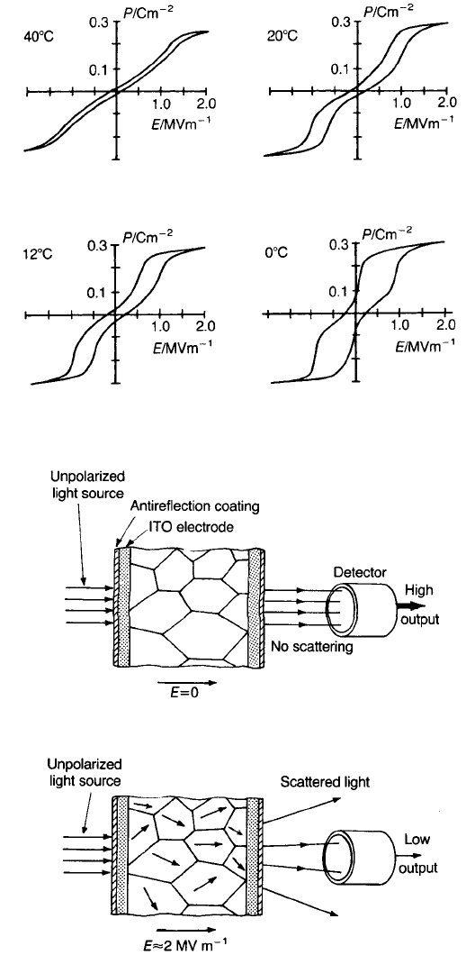
An 8.2/70/30 composition is antiferroelectric at zero field but becomes
ferroelectric when fields greater than 1 MV m
71
are applied. As a consequence
the hysteresis loop has a narrow region at low fields which develops into a
normal saturating characteristic at higher fields (Fig. 8.13). This behaviour is
temperature sensitive but occurs to a sufficient extent for practical application
between 0 and 40 8C.
The change to the ferroelectric state is accompanied by the development of
birefringence (D n 0.05) and a marked scattering of light, particularly when
the grain size lies in the 10–15 mm range. A ferroelectric domain structure only
becomes apparent when the field exceeds about 2 MV m
71
. There is uncertainty
regarding the extents to which domain boundaries and grain boundaries
contribute to the overall scattering effect.
Hot-pressed material has a grain size of about 2 mm which can be increased by
annealing at 1200 8C in a PbO atmosphere provided by burying the specimen in
powder of similar composition. Grain growth follows the relation
G 2.0t
0.4
ð8:49Þ
where G (in microns) and t (in hours) are the grain size and time respectively.
The scattering effect is exploited in the longitudinal mode, i.e. with the light
and applied field directions collinear. The major faces of the plate are coated with
ITO electrodes and antireflection layers. The arrangement of the device is shown
in Fig. 8.14.
LANTHANUM-SUBSTITUTED LEAD ZIRCONATE TITANATE 457
458 ELECTRO-OPTIC CERAMICS
Fig. 8.13 Variation in P versus E hysteresis with temperature for 8.2/70/30 PLZT.
Fig. 8.14 PLZT used in the scattering mode.
Scattering has its maximum effect in reducing the light flux over a narrow
angle, typically 38; therefore it cannot be exploited in wide-angle devices. The
‘scatter ratio’, i.e. the ratio of the detected intensity in the transparent state to
that in the scattering states, can be as high as 1000 for a plate 1 mm thick and an
applied voltage of 2000 V.
As might be expected, scattering increases with specimen thickness since the
number of scattering interfaces is thereby increased. However, for a given
thickness there is a peak in scattering at a certain crystal size, since larger
crystals, although having greater birefringence, lead to a smaller number of
interfaces in a given thickness.
8.3 Applications
Brief descriptions of a selection of applications illustrating the various electro-
optic effects and demonstrating ways in which they can be exploited are given
below.
8.3.1 Flash goggles
Flash goggles designed to protect the eyes of pilots of military aircraft from the
effects of nuclear flash are in production. Similar devices could also be of value to
arc-welders, to those who suffer eye disorders and as part of television stereo-
viewing systems.
The elements of flash goggles are a polarizer, a PLZT plate and a second polarizer
arranged as shown in Fig. 8.15. The PLZT composition, 9.2/65/35, can be prepared
by hot-pressing to a very pale yellow transparent ceramic with a grain size of about
APPLICATIONS 459
Fig. 8.15 (a) Arrangement for optical shutter; (b) detail of the electroding configuration.
2 mm. It is a slim-loop quadratic material with almost zero birefringence under zero
applied field. The R value (Table 8.1) is about 4610
716
m
2
V
72
.
For normal vision the light incident on the PLZT plate from a polarizer has its
plane of polarization turned through 908 by the birefringence induced by a
voltage (about 800 V) applied to the interdigitated electrode system (Fig. 8.15(b)).
An analyser is so oriented as to allow the emergent light through to the wearer’s
eyes. A flash of intense light is detected by a photodiode which operates a switch
that removes the voltage and closes the circuit between the electrodes. The plane
of polarization is no longer rotated and the analyser now stops most of the light.
As finally designed, the PLZT is in the form of a plate 0.4 mm thick with
corresponding grooves on both faces containing gold electrodes with gaps of
about 1 mm between the interdigitated arrays. The embedded electrodes improve
the field intensity distribution, and therefore the birefringence, across the
thickness of the plate.
Switching times between the ‘on’ and ‘off’ states are typically 100 ms and the
transmission ratios 1000:1.
8.3.2 Colour ¢lter
The optical shutter described above can function as a voltage-controlled colour
filter. The PLZT is again of the slim-loop quadratic variety, and the polarizer–
PLZT–analyser configuration as for the shutter.
When no voltage is applied, incident white light is extinguished. As the voltage
is increased, the retardation reaches a value for which the mid-spectrum ‘green’ is
retarded by l/2 and so is fully transmitted; the remainder of the partially
transmitted spectrum, along with the green, give the effect of approximately
‘white’ light. As the voltage is increased further, full-wave retardation for the
shortest-wavelength primary colour, blue, is reached, and so that colour is
extinguished. The other two primaries, red and green, are transmitted, to give the
effect of yellow light. In the same way, as one of the other two primary colours is
fully or partially extinguished, the remainder of it, together with the
complementary two primaries, is transmitted.
8.3.3 Display
A PLZT reflective display is similar in appearance to the common liquid crystal
display (LCD). The structure of the device is shown schematically in Fig. 8.16; a
suitable PLZT composition is the slim-loop quadratic 9.5/65/35.
When the polarizers P
1
and P
2
are in the parallel position and no field is
applied to the ITO electrode pattern, incident unpolarized light passes through
P
1
. The plane-polarized light then passes through the ITO electrode–PLZT
460 ELECTRO-OPTIC CERAMICS
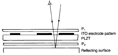
combination and the parallel P
2
, and then, after reflection, passes back through
the system to be observed. When a field is applied to the electrode pattern so as
to induce a l/2 retardation for a single passage through P
1
, the light is
extinguished at P
2
. The activated segments then appear black against a light
background. If P
1
and P
2
are arranged to be in the crossed position, the
characters appear white against a dark background. The segmented alpha-
numeric electrode pattern is of the interdigitated form described above.
The disadvantages of the PLZT device, compared with the LCD, are high
operating voltages (typically about 200 V) and high cost; an advantage is the fast
switching times.
8.3.4 Image storage
PLZT can be exploited for image storage in a variety of ways: the first of the
following two examples makes use of strain-induced birefringence and the
second light scattering (Fig. 8.14).
A strain-biased antiparallel domain configuration is induced in the plane of a
memory-type PLZT (7/65/35 with a grain size of 1.5 mm) plate approximately
60 mm thick, as shown in Fig. 8.17(a). A strain of 10
73
is achieved by bonding the
PLZT to a thicker plate of transparent Perspex and bending the combination so
that the ceramic is in tension in the convex surface. Combining a photo-
conductive layer, e.g. polyvinyl carbazole, CdS, ZnS or selenium, with the PLZT
plate allows an optical pattern to be electrically stored, read and erased.
Transparent ITO electrodes sandwich the photoconductor–PLZT combination.
When a light pattern illuminates the front face (Fig. 8.17(b)), the light passes
through the transparent electrode to interact with the photoconductive layer,
raising its conductivity. Simultaneously a voltage pulse (about 200 V) is applied
across the electrodes, the major part of which, in the illuminated regions, drops
across the ferroelectric. As a result the polarization is switched from the strain-
biased configuration to a direction approximately normal to the plate. In this
APPLICATIONS 461
Fig. 8.16 Principle of the PLZT reflective display.