Neamen D. Microelectronics: Circuit Analysis and Design
Подождите немного. Документ загружается.


A KCL equation at the output node yields
v
O
R
L
+
v
O
−(−A
OL
v
1
)
R
o
+
v
o
−v
1
R
2
= 0
(14.17)
Solving for the output voltage, we have
v
O
=
−v
1
A
OL
R
o
−
1
R
2
1
R
L
+
1
R
o
+
1
R
2
(14.18)
A KCL equation at the input node yields
i
1
=
v
1
R
i
+
v
1
−v
O
R
2
(14.19)
Combining Equations (14.18) and (14.19) and rearranging terms produces
i
1
v
1
=
1
R
if
=
1
R
i
+
1
R
2
1 + A
OL
+
R
o
R
L
1 +
R
o
R
L
+
R
o
R
2
(14.20)
Equation (14.20) describes the closed-loop input resistance of the inverting
amplifier, with a finite open-loop gain, finite open-loop input resistance, and nonzero
output resistance. In the limit as
A
OL
→∞
, we see that
1/R
if
→∞
, or
R
if
→ 0
,
which means that
v
1
→ 0
, or
v
1
is at virtual ground. This is a characteristic of an
ideal inverting op-amp.
EXAMPLE 14.2
Objective: Determine the closed-loop input resistance at the inverting terminal of an
inverting amplifier.
Consider an inverting amplifier with a feedback resistor
R
2
= 10 k
, and an op-
amp with parameters
A
OL
= 10
5
and
R
i
= 10 k
. Assume the output resistance
R
o
of the op-amp is negligible.
Solution: If
R
o
= 0
, then Equation (14.20) becomes
1
R
if
=
1
R
i
+
1 + A
OL
R
2
=
1
10
4
+
1 + 10
5
10
4
∼
=
10
−4
+10
(14.21)
The closed-loop input resistance is then
R
if
∼
=
0.1
.
Comment: The closed-loop input resistance of the inverting amplifier is a very
strong function of the finite open-loop gain. Equation (14.21) shows that the open-
loop input resistance R
i
essentially does not affect the closed-loop input resistance.
EXERCISE PROBLEM
Ex 14.2: Determine the closed-loop input resistance at the inverting terminal of an
inverting amplifier for
A
OL
= 5 ×10
4
,
R
2
= 80
k
,
R
i
= 40
k
, and
R
L
= 10
k
if (a)
R
o
= 0
and (b)
R
o
= 1
k
. (Ans. (a)
R
if
= 1.6
, (b)
R
if
= 1.78 )
1018 Part 2 Analog Electronics
nea80644_ch14_1009-1060.qxd 07/12/2009 3:44 Page 1018 pinnacle MHDQ-New:MHDQ134:MHDQ134-14:
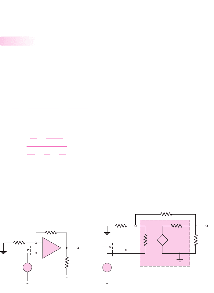
A nonzero closed-loop input resistance
R
if
in conjunction with a finite open-
loop input resistance
R
i
implies that the signal current into the op-amp is not zero, as
assumed in the ideal case. From Figure 14.4(b), we see that
v
1
= i
1
R
if
(14.22)
Therefore,
i
i
=
v
1
R
i
= i
1
R
if
R
i
(14.23)
The fraction of input signal current shunted away from
R
2
and into the op-amp is
(R
if
/R
i
)
.
Noninverting Amplifier
Closed-Loop Input Resistance
A noninverting amplifier is shown in Figure l4.5(a). The input resistance seen by the
signal source is designated
R
if
. The equivalent circuit, including a finite open-loop
gain
A
OL
, finite open-loop input differential resistance
R
i
and non-zero output resis-
tance
R
o
, is shown in Figure 14.5(b).
Writing a KCL equation at the output node yields
v
O
R
L
+
v
O
− A
OL
v
d
R
o
+
v
O
−v
1
R
2
= 0
(14.24)
Solving for the output voltage, we have
v
O
=
v
1
R
2
+
A
OL
v
d
R
o
1
R
L
+
1
R
o
+
1
R
2
(14.25)
A KCL equation at the
v
1
node yields
i
I
=
v
1
R
1
+
v
1
−v
O
R
2
(14.26)
14.2.4
Chapter 14 Nonideal Effects in Operational Amplifier Circuits 1019
R
1
R
2
v
1
v
2
v
O
v
I
–
+
R
if
R
L
v
I
R
if
–
+
R
i
R
o
A
OL
v
d
R
L
v
O
R
2
v
d
v
1
R
1
i
I
(a) (b)
+
–
+
–
–
+
+
–
Figure 14.5 (a) Noninverting amplifier and (b) noninverting amplifier equivalent circuit, for
calculating closed-loop input resistance
nea80644_ch14_1009-1060.qxd 07/12/2009 3:44 Page 1019 pinnacle MHDQ-New:MHDQ134:MHDQ134-14:

Combining Equations (14.25) and (14.26) and rearranging terms, we obtain
i
I
1 +
R
o
R
L
+
R
o
R
2
=v
1
1
R
1
+
1
R
2
1 +
R
o
R
L
+
R
o
R
2
−
R
o
R
2
2
−
A
OL
v
d
R
2
(14.27)
From Figure 14.5(b), we see that
v
d
= i
1
R
i
(14.28)
and
v
1
= v
I
−i
I
R
i
(14.29)
Substituting Equations (14.28) and (14.29) into (14.27) we obtain an equation in
i
I
and
v
I
so that the input resistance
R
if
can be found as
R
if
= v
I
/i
I
In order to simplify the algebra, we neglect the effect of
R
o
, which is normally
small. Setting
R
o
= 0
reduces Equation (14.27) to
i
I
= v
1
1
R
1
+
1
R
2
−
A
OL
v
d
R
2
(14.30)
Substituting Equations (14.28) and (14.29) into (14.30), we find that the input resis-
tance can be written in the form
R
if
=
v
I
i
I
=
R
i
(1 + A
OL
) + R
2
1 +
R
i
R
1
1 +
R
2
R
1
(14.31)
Equation (14.31) describes the closed-loop input resistance of the noninverting
amplifier with a finite open-loop gain and a finite open-loop input resistance. In the
limit as
A
OL
→∞
, or as the open-loop input resistance approaches infinity, we see
that
R
if
→∞
, which is a property of the ideal noninverting amplifier.
EXAMPLE 14.3
Objective: Determine the closed-loop input resistance at the noninverting terminal
of a noninverting amplifier.
Consider an op-amp with an open-loop gain of
A
OL
= 10
5
and an input resis-
tance of
R
i
= 10 k
in a noninverting amplifier configuration with resistor values of
R
1
= R
2
= 10 k
.
Solution: From Equation (14.31), the input resistance is
R
if
=
R
i
(1 + A
OL
) + R
2
1 +
R
i
R
1
1 +
R
2
R
1
=
10(1 + 10
5
) + 10
1 +
10
10
1 +
10
10
(14.32)
or
R
if
∼
=
5 × 10
5
k ⇒ 500 M
1020 Part 2 Analog Electronics
nea80644_ch14_1009-1060.qxd 07/12/2009 3:44 Page 1020 pinnacle MHDQ-New:MHDQ134:MHDQ134-14:
Comment: As expected, the closed-loop input resistance of the noninverting ampli-
fier is very large. Equation (14.32) shows that the input resistance is dominated by
the term
R
i
(1 + A
OL
)
. The combination of a large
R
i
and large
A
OL
produces an
extremely large input resistance, as predicted by ideal feedback theory.
EXERCISE PROBLEM
Ex 14.3: For a noninverting amplifier, the resistances are
R
2
= 99 k
and
R
1
= 1k
. The op-amp properties are:
A
OL
= 10
4
, R
i
= 40 k
, and
R
o
= 0
.
Determine the closed-loop input resistance. (Ans.
R
if
= 4.04 M
)
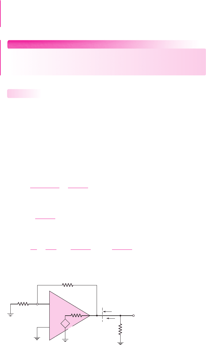
Nonzero Output Resistance
Since the ideal op-amp has a zero output resistance, the output voltage is independent
of the load impedance. The op-amp acts as an ideal voltage source and there is no
loading effect. An actual op-amp circuit has a nonzero output resistance, which
means that the output voltage, and therefore the closed-loop gain, is a function of the
load impedance.
Figure 14.6 is the equivalent circuit of both an inverting and noninverting am-
plifier and is used to find the output resistance. The op-amp has a finite open-loop
gain
A
OL
, a nonzero output resistance
R
o
, and an infinite input resistance
R
i
. To de-
termine the output resistance, we set the independent input voltages equal to zero. A
KCL equation at the output node yields
i
o
=
v
o
− A
OL
v
d
R
o
+
v
o
R
1
+ R
2
(14.33)
The differential input voltage is
v
d
=−v
1
, where
v
1
=
R
1
R
1
+ R
2
v
o
(14.34)
Combining Equations (14.34) and (14.33), we have
i
o
=
v
o
R
o
−
A
OL
R
o
−
R
1
R
1
+ R
2
v
o
+
v
o
R
1
+ R
2
(14.35(a))
14.2.5
Chapter 14 Nonideal Effects in Operational Amplifier Circuits 1021
R
1
R
2
v
1
v
o
v
d
–
+
A
OL
v
d
R
o
R
of
R
L
i
o
–
+
+
–
Figure 14.6 Equivalent circuit for calculating closed-loop output resistance
nea80644_ch14_1009-1060.qxd 07/12/2009 3:45 Page 1021 pinnacle MHDQ-New:MHDQ134:MHDQ134-14:
or
i
o
v
o
=
1
R
of
=
1
R
o
1 +
A
OL
(1 + R
2
/R
1
)
+
1
R
1
+ R
2
(14.35(b))
Since
R
o
is normally small and
A
OL
is normally large, Equation (14.35b), to a good
approximation, is as follows:
1
R
of
∼
=
1
R
o
A
OL
1 + R
2
/R
1
(14.36)
In most op-amp circuits, the open-loop output resistance
R
o
is on the order of
100
. Since
A
OL
is normally much larger than
(1 + R
2
/R
1
)
, the closed-loop output
resistance can be very small. Output resistance values in the milliohm range are
easily attained.
EXAMPLE 14.4
Objective: Determine the output resistance of an op-amp circuit.
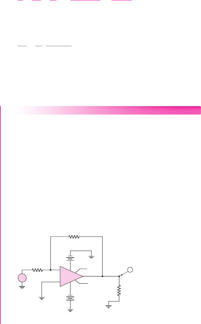
Computer Simulation Solution: Figure 14.7 shows an inverting amplifier circuit
with a standard 741 op-amp. One method of determining the output resistance is to
measure the output voltage for two different values of load resistance connected to
the output. Then, treating the amplifier as a Thevenin equivalent circuit with a fixed
source in series with an output resistance, the output resistance can be determined.
A 1 mV signal was applied. For a 10
load, the output voltage is 0.999837 mV, and
for a 20
load, the output voltage is 0.9999132 mV. This gives an output resistance
of 1.53 m
.
Comment: As mentioned, the output resistance of a voltage amplifier with negative
feedback can be very small. The ideal output resistance is zero, but a practical
op-amp circuit can have an output resistance in the milliohm range.
1022 Part 2 Analog Electronics
+
~
–
0
0
0
0
1
6
5
7
3
2
4
0
+
–
–5 V
+
–
–5 V
v
2
v
4
v
1
10 kΩ
R
2
10 kΩ
1 mV
R
1
10 Ω
R
L
–
+
v–
v+
o
S1
o
S2
mA – 741
V
Figure 14.7 Circuit using 741 op-amp to measure output resistance
nea80644_ch14_1009-1060.qxd 07/12/2009 3:45 Page 1022 pinnacle MHDQ-New:MHDQ134:MHDQ134-14:

EXERCISE PROBLEM
Ex 14.4: An op-amp with an open-loop gain of
A
OL
= 10
5
is used in a nonin-
verting amplifier configuration with a closed-loop gain of
A
CL
= 100
. Determine
the closed-loop output resistance
R
of
for: (a)
R
o
= 100
, and (b)
R
o
= 10 k
.
(Ans. (a)
R
of
= 0.1
(b)
R
of
= 10
)
Test Your Understanding
TYU 14.3 The resistors in an inverting amplifier are
R
1
= 25
k
and
R
2
= 250
k
.
Determine the minimum open-loop op-amp gain if the closed-loop gain must be within
(a) 0.1 percent of ideal and (b) 0.05 percent of ideal. (Ans. (a) 10,989, (b) 21,989)
TYU 14.4 An operational amplifier connected in a noninverting configuration has
an open-loop gain of
A
OL
= 10
5
. The resistors are
R
2
= 495 k
and
R
1
= 5k
.
(a) Determine the actual and ideal closed-loop gains. (b) If the open-loop gain de-
creases by 10 percent, determine the percent change in closed-loop gain and the actual
closed-loop gain. (Ans. (a)
A
CL
= 99.90, A
CL
(∞) = 100
(b) 0.01 %,
A
CL
= 99.89
)
TYU 14.5 A noninverting amplifier has an op-amp with an open-loop gain of
A
OL
= 2 ×10
4
. (a) Determine the maximum ideal closed-loop gain such that the ac-
tual closed-loop gain is within 0.1 percent of the ideal closed-loop value. (b) Repeat
part (a) for 0.05 percent. (Ans. (a)
A
CL
(
∞
)
= 20.02
, (b)
A
CL
(
∞
)
= 10.005)
TYU 14.6 Consider the equivalent circuit in Figure 14.4(b). If
R
i
= 10 k
, deter-
mine the percentage of input signal current i
1
shunted from
R
2
for: (a)
R
if
= 0.1
,
and (b)
R
if
= 10
. (Ans. (a)
10
−3
%
(b) 0.1 %)
TYU 14.7 Find the closed-loop input resistance of a voltage follower with op-amp
characteristics
A
OL
= 5 ×10
5
,
R
i
= 10 k
, and
R
o
= 0
. (Ans.
R
if
= 5000 M
)
14.3 FREQUENCY RESPONSE
Objective: • Analyze the open-loop and closed-loop frequency
response.
In the previous chapter, we considered the basic op-amp frequency response. Fre-
quency compensation was included as a means of stabilizing the circuit. In this section,
we will consider the bandwidth and the transient response of the closed-loop amplifier.
When a step function is applied at the op-amp input, the output voltage cannot
change instantaneously with time because of capacitance effects within the op-amp
circuit. The maximum rate at which the output changes with time is called the slew
rate. We will determine the factors that limit the slew rate.
Open-Loop and Closed-Loop Frequency Response
The frequency response of the open-loop gain can be written as
A
OL
( f ) =
A
O
1 + j
f
f
PD
(14.37)
14.3.1
Chapter 14 Nonideal Effects in Operational Amplifier Circuits 1023
nea80644_ch14_1009-1060.qxd 07/12/2009 3:45 Page 1023 pinnacle MHDQ-New:MHDQ134:MHDQ134-14:
where
A
O
is the low-frequency open-loop gain and
f
PD
is the dominant-pole
frequency. Figure 14.8 shows the Bode plot of the open-loop gain magnitude. The
dominant-pole frequency
f
PD
is shown as well as the unity-gain bandwidth
f
T
.
We showed previously that the unity-gain bandwidth is
f
T
= f
PD
A
O
(14.38)
and is also called the gain–bandwidth product. Equation (14.38) assumes that addi-
tional poles of the open-loop frequency response occur at higher frequencies than
f
T
.
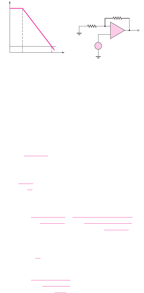
Figure 14.9 shows a noninverting amplifier. In our discussion on feedback
theory in Chapter 12, we found that, assuming ideal feedback, the closed-loop gain
A
CL
can be written
A
CL
=
A
OL
(1 + β A
OL
)
(14.39)
where
β
is the feedback transfer function. For the noninverting amplifier, this feed-
back transfer function is
β =
1
1 +
R
2
R
1
(14.40)
Combining Equations (14.37), (14.40) and (14.39), we find the expression for
the closed-loop gain as a function of frequency, as follows:
A
CL
( f ) =
A
O
1 +
A
O
1 + (R
2
/R
1
)
×
1
1 + j
f
f
PD
1 +
A
O
1 + (R
2
/R
1
)
(14.41)
Normally,
A
O
[1 +(R
2
/R
1
)]
; therefore, the low-frequency closed-loop
gain is
A
CLO
= 1 +
R
2
R
1
(14.42)
as previously determined. For
A
O
A
CLO
, Equation (14.41) is approximately
A
CL
( f ) =
A
CLO
1 + j
f
f
PD
A
O
A
CLO
(14.43)
1024 Part 2 Analog Electronics
|A
OL
|
f
f
PD
f
T
1
A
O
Figure 14.8 Bode plot, open-loop
gain magnitude
R
1
R
2
v
O
v
I
+
–
–
+
Figure 14.9 Noninverting amplifier
nea80644_ch14_1009-1060.qxd 07/12/2009 3:45 Page 1024 pinnacle MHDQ-New:MHDQ134:MHDQ134-14:
The 3 dB frequency, or small-signal bandwidth, is then
f
3dB
= f
PD
A
O
A
CLO
(14.44)
Since in most cases
A
O
A
CLO
, the bandwidth of the closed-loop system is
substantially larger than the open-loop dominant-pole frequency
f
PD
. Note also that
Equation (14.44) applies to the inverting, as well as the noninverting, amplifier in
which
A
CLO
is the magnitude of the closed-loop gain. We have seen this same band-
width extension for negative feedback several times previously.
Gain–Bandwidth Product
We can also determine the unity-gain bandwidth of the closed-loop system. From
Equation (14.43), we can write
|A
CL
( f = f
unity
)|=1 =
A
CLO
1 +
f
unity
f
PD
(A
O
/A
CLO
)
2
(14.45)
where
f
unity
is the unity-gain frequency of the closed-loop system.
If
A
CLO
1
, then Equation (14.45) yields
f
unity
f
PD
A
O
A
CLO
∼
=
A
CLO
(14.46(a))
which reduces to
f
unity
= A
CLO
f
PD
A
O
A
CLO
= f
PD
A
O
= f
T
(14.46(b))
The unity-gain frequency or bandwidth of the closed-loop system is essentially the
same as that of the open-loop amplifier.
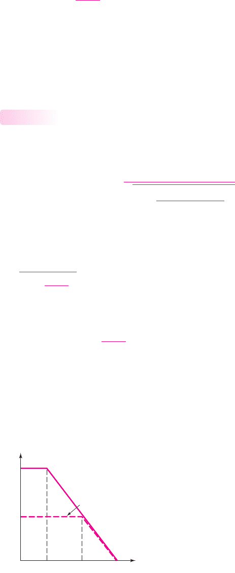
The open-loop and closed-loop frequency response curves are shown in Fig-
ure 14.10. We observed these same results in Chapter 12 in the discussion on ideal
feedback theory.
14.3.2
Chapter 14 Nonideal Effects in Operational Amplifier Circuits 1025
|A|
f
PD
f
3-dB
ff
T
A
O
1
A
CLO
Open loop
Closed loop
Figure 14.10 Bode plot, open-loop and closed-loop gain magnitude
nea80644_ch14_1009-1060.qxd 07/12/2009 3:45 Page 1025 pinnacle MHDQ-New:MHDQ134:MHDQ134-14:

EXAMPLE 14.5
Objective: Determine the unity-gain bandwidth and the maximum closed-loop gain
for a specified closed-loop bandwidth.
An audio amplifier system is to use an op-amp with an open-loop gain of
A
O
=
2 × 10
5
and a dominant-pole frequency of 5 Hz. The bandwidth of the audio system
is to be 20 kHz. Determine the maximum closed-loop gain for the audio amplifier.
Solution: The unity-gain bandwidth is found as
f
T
= f
PD
A
O
= (5)(2 ×10
5
) = 10
6
Hz ⇒ 1MHz
Since the gain–bandwidth product is a constant, we have
f
3-dB
· A
CL
= f
T
where f
3-dB
is the closed-loop bandwidth and
A
CL
is the closed-loop gain. The max-
imum closed-loop gain is then
A
CL
=
f
T
f
3-dB
=
10
6
20 × 10
3
= 50
Comment: If the closed-loop gain is less than or equal to 50, then the required band-
width of 20 kHz for the audio amplifier will be realized.
EXERCISE PROBLEM
Ex 14.5: An op-amp with open-loop parameters of
A
OL
= 2 ×10
5
and
f
PD
= 5
Hz is connected in a noninverting amplifier configuration with a low-
frequency closed-loop gain of
A
CLO
= 30
. An input voltage signal of
v
I
= 100 sin
(
2π ft
)
μ
V is applied. (a) What is the closed-loop bandwidth?
(b) What is the low-frequency output voltage? (c) Determine the peak amplitude of
the output voltage if the frequency of the signal is (i)
f = 5
kHz, (ii)
f = 50
kHz,
and (iii)
f = 200
kHz. (Ans. (a)
f
3-dB
= 33.3
kHz; (b)
v
O
= 3 sin
(
2π ft
)
mV;
(c) (i)
∼
=
3
mV, (ii) 1.663 mV, (iii) 0.493 mV)
Slew Rate
Implicit in the frequency response analysis for the closed-loop amplifier is the
assumption that the sinusoidal input signals are small. If a large sinusoidal signal or
step function is applied to an op-amp circuit, the input stage can be overdriven and
the small-signal model will no longer apply.
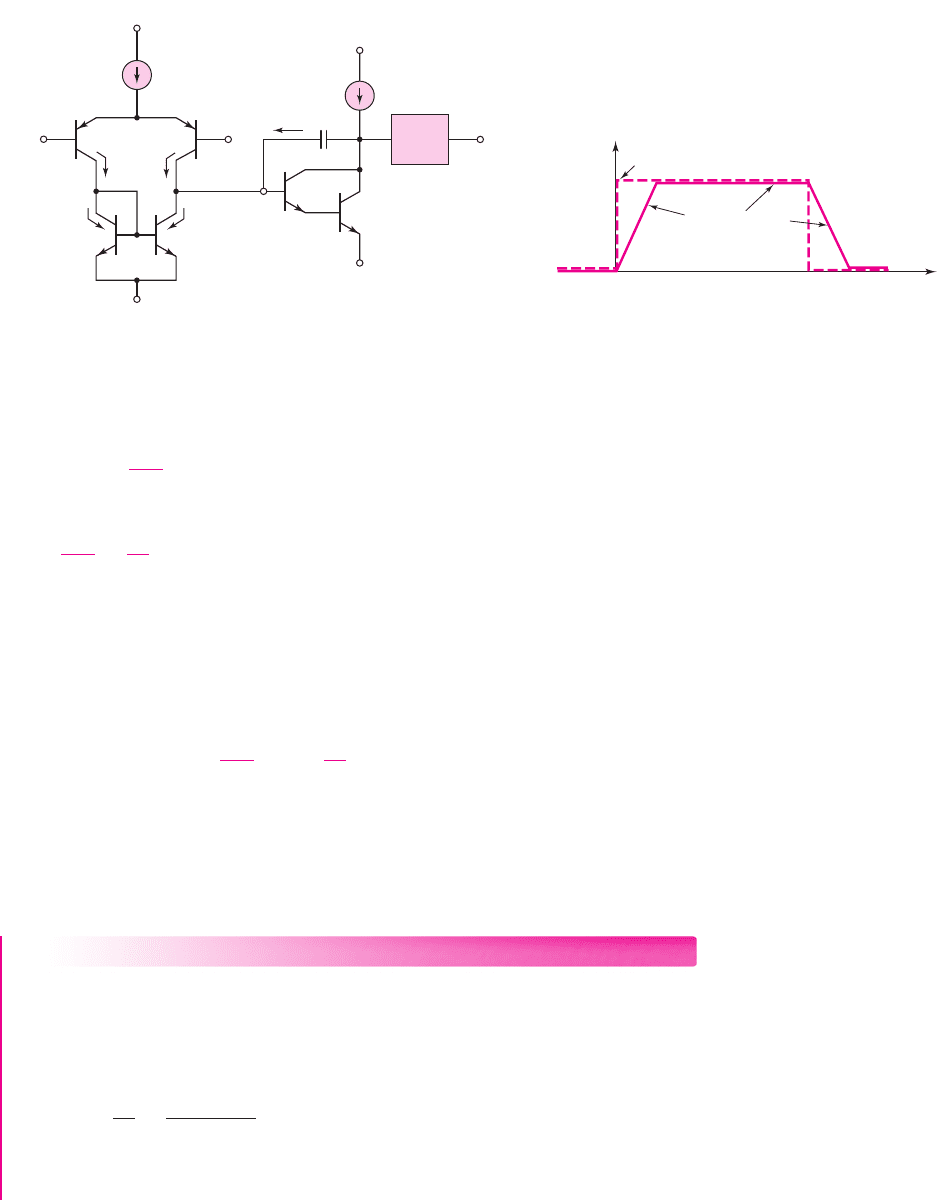
Figure 14.11 shows a simplified op-amp circuit. If a large step voltage (greater
than 120 mV) is applied at
v
2
with
v
1
held at ground potential, then
Q
2
is effectively
cut off, which means
i
C2
∼
=
0
and
i
C1
∼
=
I
Q
. The entire bias current is switched to
Q
1
.
Since
i
C3
∼
=
i
C1
, then
i
C3
∼
=
I
Q
; since
Q
3
–
Q
4
form a current mirror, then we also
have
i
C4
∼
=
I
Q
.
The base current into
Q
5
is very small; therefore, the current through the compen-
sation capacitor
C
1
is
i
O
= i
C4
= I
Q
. Since the voltage gain of the emitter-follower
output stage is essentially unity, the capacitor current can be written as
i
O
= C
1
d(v
O
−v
O1
)
dt
(14.47)
14.3.3
1026 Part 2 Analog Electronics
nea80644_ch14_1009-1060.qxd 07/12/2009 3:45 Page 1026 pinnacle MHDQ-New:MHDQ134:MHDQ134-14:
The gain of the second stage is large, which means that
v
O1
v
O
. Equa-
tion (14.47) then becomes
i
O
∼
=
C
1
dv
O
dt
= I
Q
(14.48)
or
dv
O
dt
=
I
Q
C
1
(14.49)
The maximum current through the compensation capacitor is limited to the bias cur-
rent
I
Q
; consequently, the maximum rate at which the output voltage can change is
also limited by the bias current
I
Q
.
The maximum rate of change of the output voltage is the slew rate of the
op-amp, the units of which are usually given as volts per microsecond. From Equa-
tion (14.49), we have
Slew rate (SR) =
dv
O
dt
max
=
I
Q
C
1
(14.50)
Although the rate of change in output voltage can be either positive or negative, the
slew rate is defined as a positive quantity.
Figure 14.12 shows the slew-rate limited response of an op-amp voltage follower
to a rectangular input voltage pulse. Note the trapezoidal shaped output response. The
time needed to reach the full-scale response is approximately
V
O
(max)/SR
.
EXAMPLE 14.6
Objective: Calculate the slew rate of the 741 op-amp.
From the previous chapter, the bias current in the 741 op-amp is
I
Q
= 19 μA
and the internal frequency compensation capacitor is
C
1
= 30
pF.
Solution: From Equation (14.50), the slew rate is
SR =
I
Q
C
1
=
19 × 10
−6
30 × 10
−12
= 0.63 ×10
6
V/s ⇒ 0.63 V/μs
Comment: The partial data sheet in Table 14.1 for the 741 op-amp lists the typical
slew rate as
0.7V/μs
, which is in close agreement with our calculated value.
Chapter 14 Nonideal Effects in Operational Amplifier Circuits 1027
V
+
V
+
V
–
V
–
I
Q
I
Q
Q
3
Q
4
i
C1
v
O1
v
O
i
C3
i
C4
i
C2
v
2
C
1
v
1
Q
2
Q
1
Q
6
Q
5
Emitter-
follower
output
stage
i
O
A
v3
≅ 1
Figure 14.11 Simplified op-amp for calculating slew rate
V(t)
Time
0
V
O
(max)
Input pulse
Output response
Slope = +SR
Slope = –SR
Figure 14.12 Slew-rate-limited response of voltage
follower to rectangular input voltage pulse
nea80644_ch14_1009-1060.qxd 07/12/2009 3:45 Page 1027 pinnacle MHDQ-New:MHDQ134:MHDQ134-14: