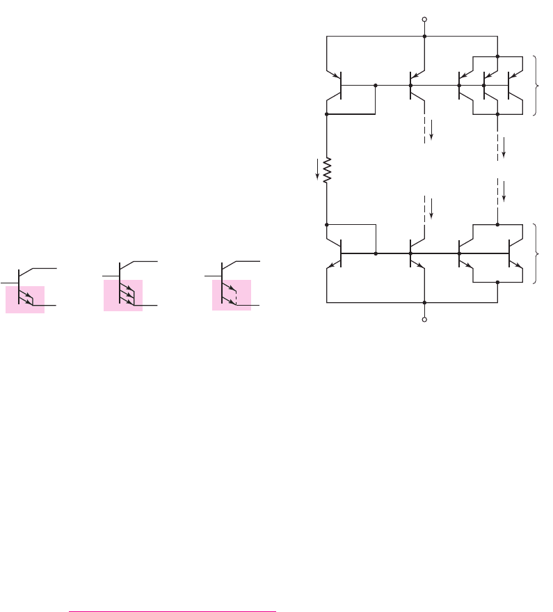
Neamen D. Microelectronics: Circuit Analysis and Design
Подождите немного. Документ загружается.


698 Part 2 Analog Electronics
If we replace I
C1
by I
C2
in Equation (10.21), the reference current becomes
I
REF
= I
C2
+ I
B3
=
1 + β
2 + β
I
C3
+
I
C3
β
(10.24)
Rearranging terms, we can solve for the output current,
I
C3
= I
O
= I
REF
×
1
1 +
2
β(2 +β)
(10.25)
This current relationship is essentially the same as that of the previous three-
transistor current source.
The difference between the two three-transistor current-source circuits is the
output resistance. In the Wilson current source, the output resistance looking into the
collector of Q
3
is
R
o
∼
=
βr
o3
/2
, which is approximately a factor
β/2
larger than that
of either the two-transistor source or the basic three-transistor source. This means
that, in the Wilson current source, the change in bias current I
O
with a change in out-
put collector voltage is much smaller.
Output Voltage Swing
If we consider the equivalent circuit in Figure 10.3, we see that the maximum possi-
ble swing in the output voltage is a function of the minimum possible collector–
emitter voltage of Q
2
. For the two-transistor current source in this figure, the
minimum value of
V
CE2
= V
CE
(sat), which may be on the order of 0.1 to 0.3 V.
For the cascode and Wilson current sources, the minimum output voltage is
V
BE
+ V
CE
(sat) above the negative power supply voltage, which may be on the
order of 0.7 to 0.9 V. For circuits biased at
±5
V, for example, this increased mini-
mum voltage may not be a serious problem. However, as the voltages decrease in
low-power circuits, this minimum voltage effect may become more serious.
Problem-Solving Technique: BJT Current Source Circuits
1. Sum currents at the various nodes in the circuit to find the relation between
the reference current and the bias current.
2. To find the output resistance of the current source circuit, place a test voltage
at the output node and analyze the small-signal equivalent circuit. Keep in
mind that the reference current is a constant, which may make some of the
base voltages constant or at ac ground.
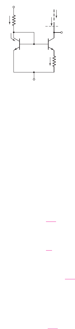
Widlar Current Source
In the current-source circuits considered thus far, the load and reference currents
have been nearly equal. For a two-transistor current source, such as that shown in
Figure 10.2(a), if we require a load current of
I
O
= 10 μ
A, then, for
V
+
= 5
V and
V
−
=−5
V, the required resistance value is
R
1
=
V
+
− V
BE
− V
−
I
REF
∼
=
5 − 0.7 −(−5)
10 × 10
−6
= 930 k
In ICs, resistors on the order of 1 M
require large areas and are difficult to fabricate
accurately. We therefore need to limit IC resistor values to the low kilohm range.
10.1.3
nea80644_ch10_687-752.qxd 6/19/09 4:27 AM Page 698 pmath DATA-DISK:Desktop Folder:18.6.09:MHDQ134-10:
Chapter 10 Integrated Circuit Biasing and Active Loads 699
The transistor circuit in Figure 10.9, called a Widlar current source, meets this
objective. A voltage difference is produced across resistor R
E
, so that the B–E volt-
age of Q
2
is less than the B–E voltage of Q
1
. A smaller B–E voltage produces a
smaller collector current, which in turn means that the load current I
O
is less than the
reference current I
REF
.
Current Relationship
If
β 1
for Q
1
and Q
2
, and if the two transistors are identical, then
I
REF
∼
=
I
C1
= I
S
e
V
BE1
/V
T
(10.26(a))
and
I
O
= I
C2
= I
S
e
V
BE2
/V
T
(10.26(b))
Solving for the B–E voltages, we have
V
BE1
= V
T
ln
I
REF
I
S
(10.27(a))
and
V
BE2
= V
T
ln
I
O
I
S
(10.27(b))
Combining Equations (10.27(a)) and (10.27(b)) yields
V
BE1
− V
BE2
= V
T
ln
I
REF
I
O
(10.28)
From the circuit, we see that
V
BE1
− V
BE2
= I
E2
R
E
∼
=
I
O
R
E
(10.29)
When we combine Equations (10.28) and (10.29), we obtain:
I
O
R
E
= V
T
ln
I
REF
I
O
(10.30)
This equation gives the relationship between the reference and bias currents.
I
REF
I
C2
= I
O
I
C1
I
E2
V
+
V
–
R
1
R
E
R
o
V
C2
Q
1
Q
2
++
––
++
––
V
BE1
V
BE2
Figure 10.9 Widlar current source
nea80644_ch10_687-752.qxd 6/19/09 4:27 AM Page 699 pmath DATA-DISK:Desktop Folder:18.6.09:MHDQ134-10:

700 Part 2 Analog Electronics
DESIGN EXAMPLE 10.4
Objective: Design a Widlar current source to achieve specified reference and load
currents.
Specifications: The circuit to be designed has the configuration shown in Figure 10.9.
Assume bias voltages of
V
+
=+5
V and
V
−
=−5
V. Assume
V
BE1
= 0.7
V. De-
sign the circuit such that
I
REF
= 1
mA and
I
O
= 12 μ
A.
Choices: Assume that matched transistors are available and that base currents can be
neglected. Also assume that IC resistors of any value can be fabricated.
Solution: Resistance R
1
is
R
1
=
V
+
− V
BE1
− V
−
I
REF
=
5 − 0.7 −(−5)
1
= 9.3k
Resistance R
E
is, from Equation (10.30),
R
E
=
V
T
I
O
ln
I
REF
I
O
=
0.026
0.012
ln
1
0.012
= 9.58 k
From Equation (10.29), we can determine the difference between the two B–E volt-
ages, as follows:
V
BE1
− V
BE2
= I
O
R
E
= (12 ×10
−6
)(9.58 × 10
3
) = 0.115 V
Trade-offs: A slight variation in
V
BE1
and slight tolerance variations in resistor
values will change the current values slightly. These effects are evaluated in end-of-
chapter problems.
Comment: A difference of 115 mV in the B–E voltages of Q
1
and Q
2
produces
approximately two orders of magnitude difference between the reference and load
currents. Therefore, we can produce a very low bias current using resistors in the
low kilohm range. These resistors can easily be fabricated in an IC. Including the
resistor R
E
gives the designer additional versatility in adjusting the load to reference
current ratio.
EXERCISE PROBLEM
Ex 10.4: Consider the Widlar current source in Figure 10.9. The bias voltages are
V
+
= 3
V and
V
−
=−3V
. Design the circuit such that
I
O
= 20 μ
A and
I
REF
= 100 μ
A. Assume
V
BE1
= 0.6
V and
V
A
=∞
, and neglect base currents.
Determine
R
1
, R
E
, and
V
BE2
. (Ans.
R
1
= 54
k
,
R
E
= 2.09
k
,
V
BE2
= 0.558
V)
In our analysis of constant-current source circuits, we have assumed a piecewise
linear approximation for the B–E voltage,
V
BE
(on). However, in the Widlar current
source and other current-source circuits, the piecewise linear approximation is not
adequate, since the B–E voltages are not all equal. With the exponential relationship
between collector current and base–emitter voltage, as shown in Equations (10.26(a))
and (10.26(b)), a small change in B–E voltage produces a large change in collector
current. To take this variation into account, either the reverse-biased saturation
current I
S
or the B–E voltage at a particular collector current must be known.
Also in our analysis, we have assumed that the temperatures of all transistors are
equal. Maintaining equal temperatures is important for proper circuit operation.
nea80644_ch10_687-752.qxd 6/19/09 4:27 AM Page 700 pmath DATA-DISK:Desktop Folder:18.6.09:MHDQ134-10:
Chapter 10 Integrated Circuit Biasing and Active Loads 701
EXAMPLE 10.5
Objective: To determine the currents in a Widlar current source circuit.
Assume the Widlar source is biased at
V
+
=+5
V and
V
−
=−5
V, and assume
resistor values
R
1
= 7k
and
R
E
= 4k
. Also assume
V
BE1
= 0.7
V.
Solution: The reference current is found to be
I
REF
=
V
+
− V
BE1
− V
−
R
1
=
5 − 0.7 −(−5)
7
= 1.33 mA
The load current is found from the relation
I
O
R
E
= V
T
ln
I
REF
I
O
or
I
O
(4) = 0.026 ln
1.33
I
O
A transcendental equation cannot be solved directly. A computer solution or a trial
and error solution yields
I
O
∼
=
25.7 μA
Comment: In this case, the difference between the two base–emitter voltages is
I
O
R
E
∼
=
103 mV
. Again, a relatively small difference in the two base–emitter volt-
ages can produce a relatively large difference between the reference and load currents.
EXERCISE PROBLEM
Ex 10.5: Consider the circuit in Figure 10.10. Assume the reference current is
I
REF
= 120 μ
A and assume the transistor parameters are
I
S1
= I
S2
= 2 ×10
−16
A.
Neglect base currents. (a) Find
V
BE1
. (b) If
I
O
= 50 μ
A, determine
V
BE2
and
R
E
.
(c) Find
I
O
if
R
E
= 700
. What is
V
BE2
? (Ans. (a)
V
BE1
= 0.7051
V;
(b)
R
E
= 455
,
V
BE2
= 0.6824
V; (c)
I
O
= 40.4 μ
A,
V
BE2
= 0.6768
V)
Output Resistance
The change in load current with a change in voltage V
C2
of the Widlar current source
in Figure 10.9 can be expressed as
dI
O
dV
C2
=
1
R
o
(10.31)
where R
o
is the output resistance looking into the collector of Q
2
. This output resis-
tance can be determined by using the small-signal equivalent circuit in Figure 10.11(a).
(Again, we use the phasor notation in small-signal analyses.) The base, collector, and
emitter terminals of each transistor are indicated on the figure.
First, we calculate the resistance R
o1
looking into the base of Q
1
. Writing a KCL
equation at the base of Q
1
, we obtain
I
x1
=
V
x1
r
π1
+ g
m1
V
π1
+
V
x1
r
o1
R
1
(10.32)
V
+
I
O
Q
1
Q
2
R
E
I
REF
V
–
Figure 10.10 Figure or
Exercise Ex 10.5
nea80644_ch10_687-752.qxd 6/19/09 4:27 AM Page 701 pmath DATA-DISK:Desktop Folder:18.6.09:MHDQ134-10:
702 Part 2 Analog Electronics
Noting that
V
π1
= V
x1
, we have
1
R
o1
=
I
x1
V
x1
=
1
r
π1
+ g
m1
+
1
r
o1
R
1
(10.33(a))
or
R
o1
= r
π1
1
g
m1
r
o1
R
1
(10.33(b))
Next, we calculate the approximate value for R
o1
. If
I
REF
= 1
mA, then for
β = 100, r
π1
= 2.6k
and
g
m1
= 38.5
mA/V. Assume that
R
1
= 9.3k
and
r
o1
=∞
. For these conditions,
R
o1
∼
=
0.026 k = 26
. For a load current of
I
O
= 12 μA
, we find
r
π2
= 217 k
. Resistance R
o1
is in series with
r
π2
, and since
R
o1
r
π2
, we can neglect the effect of R
o1
, which means that the base of Q
2
is
essentially at signal ground.
Now we determine the output resistance at the collector of Q
2
, using the simpli-
fied equivalent circuit in Figure 10.11(b). The Norton equivalent of the current
source g
m2
V
π2
and resistance r
o2
can be transformed into a Thevenin equivalent
circuit, as shown in Figure 10.11(c). Resistances
r
π2
and R
E
are in parallel; therefore,
we define
R
E
= R
E
r
π2
. Since the current through the parallel combination of R
E
and
r
π2
is I
x
, we have
V
π2
=−I
x
R
E
(10.34)
+
–
r
p 1
g
m1
V
p 1
g
m2
V
p 2
r
o2
r
o1
R
o
=
R
o1
+
–
V
p 2
E
1
E
2
R
1
C
2
C
1
B
1
V
x1
B
2
+
–
V
p 1
r
p 2
V
x
I
x
V
x
R
E
I
x
I
x1
(a)
+
–
g
m2
V
p 2
r
o2
R
o
=
+
–
V
p 2
r
p 2
V
x
I
x
V
x
R
E
I
x
+
–
g
m2
r
o2
V
p 2
r
o2
R
o
+
–
V
p 2
r
p 2
V
x
R
E
I
x
+
–
(b) (c)
Figure 10.11 (a) Small-signal equivalent circuit for determining output resistance of Widlar
current source, (b) simplified equivalent circuit for determining output resistance, and
(c) equivalent circuit after a Norton transformation
nea80644_ch10_687-752.qxd 6/19/09 4:27 AM Page 702 pmath DATA-DISK:Desktop Folder:18.6.09:MHDQ134-10:

Chapter 10 Integrated Circuit Biasing and Active Loads 703
Writing a KVL equation, we obtain
V
x
= I
x
r
o2
− g
m2
r
o2
V
π2
+ I
x
R
E
(10.35)
Substituting Equation (10.34) into (10.35) yields
V
x
I
x
= R
o
= r
o2
1 + R
E
g
m2
+
1
r
o2
(10.36)
Normally,
(1/r
o2
) g
m2
; therefore,
R
o
∼
=
r
o2
(1 + g
m2
R
E
)
(10.37)
The output resistance of the Widlar current source is a factor
(1 + g
m2
R
E
)
larger than
that of the simple two-transistor current source.
EXAMPLE 10.6
Objective: Determine the change in load current with a change in collector voltage
in a Widlar current source.
Consider the circuit in Figure 10.9. The parameters are:
V
+
= 5
V,
V
−
=−5
V,
R
1
= 9.3k
, and
R
E
= 9.58 k
. Let
V
A
= 80
V and
β = 100
. Determine the
change in I
O
as V
C2
changes by 4 V.
Solution: From Example 10.4, we have
I
O
= 12 μ
A. The small-signal collector
resistance is
r
o2
=
V
A
I
O
=
80
0.012
⇒ 6.67 M
We can determine that
g
m2
=
I
O
V
T
=
0.012
0.026
= 0.462 mA/V
and
r
π2
=
βV
T
I
O
=
(100)(0.026)
0.012
= 217 k
The output resistance of the circuit is
R
o
= r
o2
[1 + g
m2
(R
E
r
π2
)] = (6.67) · [1 +(0.462)(9.58217)] = 34.9M
From Equation (10.31), the change in load current is
dI
O
=
1
R
o
dV
C2
=
1
34.9 × 10
6
×4 ⇒ 0.115 μA
The percentage change in output current is then
dI
O
I
O
=
0.115
12
= 0.0096 ⇒ 0.96%
Comment: The stability of the load current, as a function of a change in output volt-
age, is improved in the Widlar current source, compared to the simple two-transistor
current source.
nea80644_ch10_687-752.qxd 6/19/09 4:27 AM Page 703 pmath DATA-DISK:Desktop Folder:18.6.09:MHDQ134-10:
704 Part 2 Analog Electronics
EXERCISE PROBLEM
Ex 10.6: A Widlar current source is shown in Figure 10.9. The parameters are:
V
+
= 5
V,
V
−
= 0
,
I
REF
= 0.70
mA, and
I
O
= 25 μA
at
V
C2
= 1
V. The tran-
sistor parameters are:
β = 150
,
V
BE1
(on) = 0.7
V, and
V
A
= 100
V. Determine
the change in I
O
when V
C2
changes from 1 V to 4 V. (Ans.
dI
O
= 0.176 μ
A)
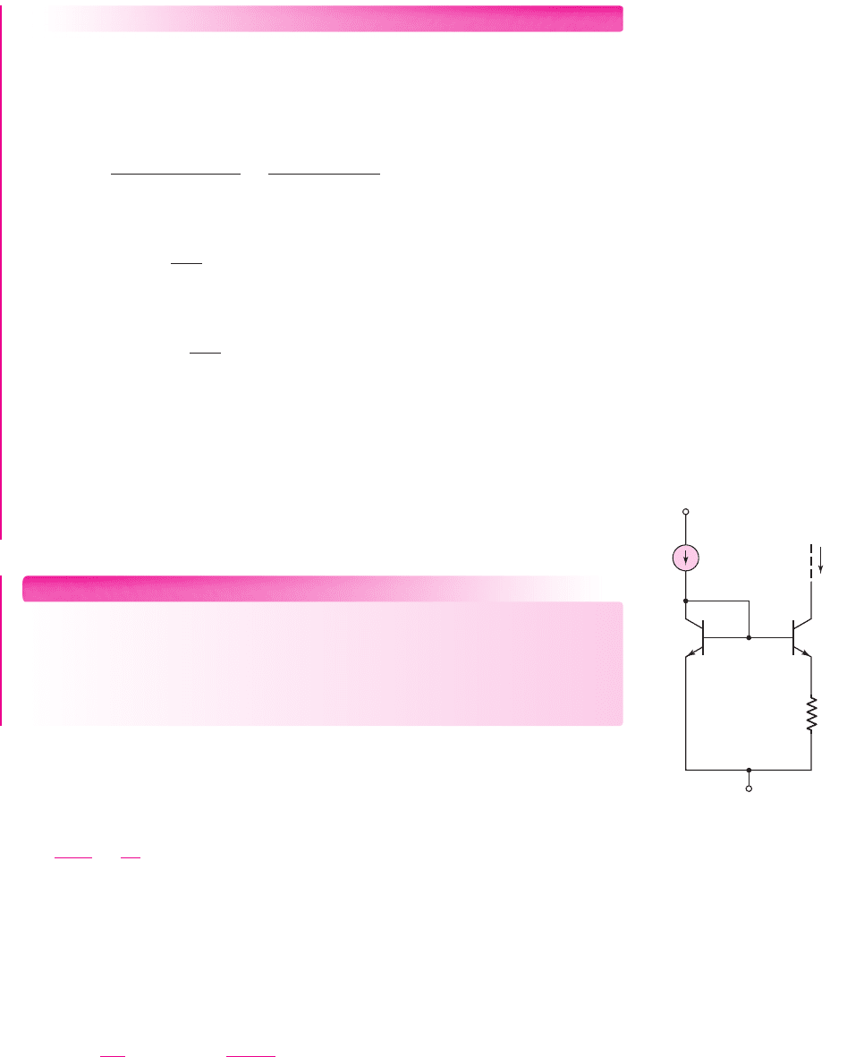
Multitransistor Current Mirrors
In the previous current sources, we established a reference current and one load
current. In the two-transistor current source in Figure 10.2(a), the B–E junction of the
diode-connected transistor Q
1
is forward biased when the bias voltages
V
+
and
V
−
are applied. Once
V
BE
is established, the voltage is applied to the B–E junction of Q
2
,
which turns Q
2
on and produces the load current I
O
.
The B–E voltage of Q
1
can also be applied to additional transistors, to generate
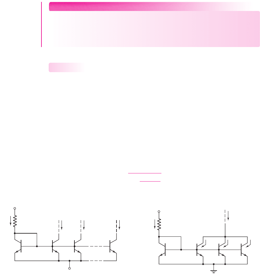
multiple load currents. Consider the circuit in Figure 10.12. Transistor Q
R
, which is
the reference transistor, is connected as a diode. The resulting B–E voltage of Q
R
,
established by I
REF
, is applied to N output transistors, creating N load currents. The
relationship between each load current and the reference current, assuming all
transistors are matched and
V
A
=∞
, is
I
O1
= I
O2
=···=I
ON
=
I
REF
1 +
(1 + N)
β
(10.38)
10.1.4
I
O1
I
REF
V
+
V
–
Q
R
R
1
Q
1
I
O2
I
ON
Q
2
Q
N
Figure 10.12 Multitransistor current mirror
I
O
I
REF
V
+
Q
R
R
1
Q
1
I
1
Q
2
I
2
Q
3
I
3
Figure 10.13 Multioutput transistor current source
The collectors of multiple output transistors can be connected together, chang-
ing the load current versus reference current relationship. As an example, the circuit
in Figure 10.13 has three output transistors with common collectors and a load
current I
O
. We assume that transistors Q
R
, Q
1
, Q
2
, and Q
3
are all matched. If the
current gain
β
is very large, the base currents can be neglected,
I
1
= I
2
= I
3
= I
REF
,
and the load current is
I
O
= 3I
REF
. [Note: This process is not recommended for
discrete devices, since a mismatch between devices will generally cause one device
to carry more current than the other devices.]
Connecting transistors in parallel increases the effective B–E area of the device.
In actual IC fabrication, the B–E area would be doubled or tripled to provide a load
current twice or three times the value of I
REF
.
nea80644_ch10_687-752.qxd 6/19/09 4:27 AM Page 704 pmath DATA-DISK:Desktop Folder:18.6.09:MHDQ134-10:
Chapter 10 Integrated Circuit Biasing and Active Loads 705
N
(a) (b) (c)
Figure 10.14 Equivalent circuit symbols (a) two
transistors in parallel, (b) three transistors in
parallel, and (c) N transistors in parallel
I
O2
I
O4
I
REF
V
+
V
–
I
O1
I
O3
Q
R2
R
1
Q
1
Q
2
Q
3
Q
4
+
–
V
EB
+
–
V
BE
Q
R1
Figure 10.15 Generalized current mirror
Rather than drawing each set of parallel output transistors, we can use the circuit
symbols in Figure 10.14. Figure 10.14(a) is the equivalent symbol for two transis-
tors connected in parallel, Figure 10.14(b) is for three transistors in parallel, and
Figure 10.14(c) is for N transistors in parallel. Although the transistors appear to
be multiemitter devices, we are simply indicating devices with different B–E junc-
tion areas.
A generalized current mirror is shown in Figure 10.15. We can use pnp transistors
to establish the load currents, as shown in the figure. Transistors Q
R1
and Q
R2
are
connected as diodes. The reference current is established in the branch of the circuit
that has the diode-connected transistors, resistor R
1
, and bias voltages, and is given by
I
REF
=
V
+
− V
EB
(Q
R1
) − V
BE
(Q
R2
) − V
−
R
1
(10.39)
If
β
for each transistor is very large, the base current effects can be neglected.
Then the load current I
O1
generated by output transistor Q
1
is equal to I
REF
. Likewise,
Q
3
generates a load current I
O3
equal to I
REF
. Implicitly, all transistors are identi-
cal, all load transistors are biased in their forward-active region, and all transistor
Early voltages are infinite. Transistor Q
2
is effectively two transistors in parallel;
then, since all transistors are identical,
I
O2
= 2I
REF
. Similarly, Q
4
is effectively
three transistors connected in parallel, which means that the load current is
I
O4
= 3I
REF
.
In the above discussion, we neglected the effect of base currents. However, a
finite
β
causes the collector currents in each load transistor to be smaller than I
REF
since the reference current supplies all base currents. This effect becomes more
severe as more load transistors are added.
nea80644_ch10_687-752.qxd 6/19/09 4:27 AM Page 705 pmath DATA-DISK:Desktop Folder:18.6.09:MHDQ134-10:

706 Part 2 Analog Electronics
DESIGN EXAMPLE 10.7
Objective: Design a generalized current mirror to meet a set of specifications.
Specifications: The circuit to be designed has the configuration shown in Fig-
ure 10.15. The bias voltages are
V
+
=+5
V and
V
−
=−5
V. Neglect base currents
and assume
V
BE
= V
EB
= 0.6
V. Design the circuit such that
I
O2
= 400 μ
A. Deter-
mine the other currents and find the value for R
1
.
Solution: For
I
O2
= 400 μ
A, we have
I
REF
= I
O1
= I
O3
= 200 μA and I
O4
= 600 μA
Resistor R
1
is
R
1
=
V
+
− V
EB
(Q
R1
) − V
BE
(Q
R2
) − V
−
I
REF
=
5 − 0.6 −0.6 −(−5)
0.2
or
R
1
= 44 k
Trade-offs: Base currents were neglected in this ideal design. Including the effects
of base currents (a finite
β
) will change the current and resistor values slightly.
Comment: If the load and reference currents are to be within a factor of approxi-
mately four of each other, it is more efficient, from an IC point of view, to adjust the
B–E areas of the transistors to achieve the specified currents rather than use the
Widlar current source with its additional resistors.
Design Pointer: This example demonstrates that a single reference current can be
used to induce multiple load currents, which can be used to bias various stages of a
complex circuit. We will see specific examples of this technique in Chapter 13 when
we consider actual operational amplifier circuits.
EXERCISE PROBLEM
*Ex 10.7: Figure 10.12 shows the N-output current mirror. Assuming all transis-
tors are matched, with a finite gain and
V
A
=∞
, derive Equation (10.38). If each
load current must be within 10 percent of I
REF
, and if
β = 50
, determine the max-
imum number of load transistors that can be connected. (Ans.
N = 4
)
Test Your Understanding
TYU 10.1 The circuit parameters for the current source shown in Figure 10.2(b) are
V
+
= 2.5
V and
V
−
=−2.5
, and the transistor parameters are
V
BE
(
on
)
= 0.7
V,
β = 120
, and
V
A
=∞
. Design the circuit such that
I
O
= 0.20
mA. What is the value
of
I
REF
? (Ans.
R
1
= 21.15
k
,
I
REF
= 0.2033
mA)
TYU 10.2 Consider the circuit in Figure 10.2(a). The current source is
I
REF
= 150 μ
A.
The transistor parameters are
I
S1
= 8 ×10
−15
A,
I
S2
= 5 ×10
−15
A, and
β = 150
.
Determine
V
BE1
and
I
O
. (Ans.
V
BE1
= 0.6150
V,
I
O
= 93.75 μ
A)
TYU 10.3 For the Wilson current source in Figure 10.8, the transistor parameters are:
V
BE
(on) = 0.7
V,
β = 50
, and
V
A
=∞
. For
I
REF
= 0.50
mA, determine all currents
nea80644_ch10_687-752.qxd 6/19/09 4:27 AM Page 706 pmath DATA-DISK:Desktop Folder:18.6.09:MHDQ134-10:
Chapter 10 Integrated Circuit Biasing and Active Loads 707
shown in the figure. (Ans.
I
O
= 0.4996
mA,
I
B3
= 9.99 μ
A,
I
E3
= 0.5096
mA,
I
C2
= 0.490
mA
= I
C1
, I
B1
= I
B2
= 9.80 μ
A)
TYU 10.4 The circuit and transistor parameters for the circuits in Figures 10.2(b) and
10.9 are
V
+
= 3
V,
V
−
=−3
V,
I
REF
= 1
mA,
β = 200
, and
V
A
= 50
V. For the
circuit in Figure 10.9, let
R
E
= 2
k
. For each circuit, determine (a)
I
O
, (b)
R
o
, and
(c)
dI
O
/I
O
(in percent) for
V
C2
= 3
V. (Ans. (a)
I
O
= 1
mA,
I
O
= 41.4 μ
A;
(b)
R
o
= 50
k
,
R
o
= 5.0
M
; (c) 6%, 1.45%)
10.2 FET CURRENT SOURCES
Objective: • Analyze and understand the characteristics of various
MOSFET (and a few JFET) circuits used to provide a constant output
current.
Field-effect transistor integrated circuits are biased with current sources in much the
same way as bipolar circuits. We will examine the relationship between the reference
and load currents, and will determine the output impedance of the basic two-transistor
MOSFET current source. We will then analyze multi-MOSFET current-source cir-
cuits to determine reference and load current relationships and output impedance.
Finally, we will discuss JFET constant-current source circuits.
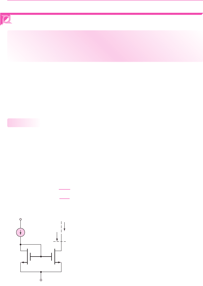
Basic Two-Transistor MOSFET Current Source
Current Relationship
Figure 10.16 shows a basic two-transistor NMOS current source. The drain and
source terminals of the enhancement-mode transistor M
1
are connected, which
means that M
1
is always biased in the saturation region. Assuming
λ = 0
, we can
write the reference current as
I
REF
= K
n1
(V
GS
− V
TN1
)
2
(10.40)
Solving for
V
GS
yields
V
GS
= V
TN1
+
I
REF
K
n1
(10.41)
10.2.1
I
D2
= I
O
I
REF
V
–
R
o
V
+
+
–
V
GS
+
–
V
DS1
+
–
V
DS2
M
1
M
2
Figure 10.16 Basic two-transistor MOSFET current source
nea80644_ch10_687-752.qxd 6/19/09 4:27 AM Page 707 pmath DATA-DISK:Desktop Folder:18.6.09:MHDQ134-10: