Yam, Kit L. (ed.). The Wiley encyclopedia of packaging technology
Подождите немного. Документ загружается.


canmaking. Today most cans are identified by their di-
mensions and not by name. Some of those names and can
sizes listed are no longer applicable.
International standards for can sizes have been devel-
oped under auspices of the International Standards Orga-
nization (ISO), and cans are named in many countries on
the basis of ISO standards. The specifications, measure-
ments, and nomenclatures in ISO standards are used to
describe cans in several countries. As can sizes listed in
the ISO standards are the least likely to be restricted in
international trade, it would be advisable when develop-
ing a new product line or changing package sizes to
consider can sizes from the ISO standards. To comply
with the ISO standards, the Can Manufacturers Institute
has now recommended that U.S. can sizes be identified in
metric measurements according to their body plug dia-
meter rounded to the nearest whole number of milli-
meters, and their height must be rounded to the nearest
whole number of millimeters as shipped from the can
factory. For example, the 307 113 is identified as
83 46 mm.
Normally, during the selection of a container size for a
specific item the concerns are not with providing a can
with minimum surface area, but rather to minimize
package metal weight (i.e., cost) within practical limita-
tions. As an example, the filling, processing, and end
attachment operations demand that the circular ends be
made of thicker metal than the cylindrical body. The cost
impact tends to reduce end diameter while increasing
body height compared with the theoretical dimensions
for minimum surface area. Furthermore the ends are
attached to the body with mechanically overlapped
metal formed into the body and ends. Again, the require-
ment for thicker metal for the ends would favor smaller
diameter.
Similarly, the body beads (for strength against can
collapse) and end beads (for rigidity) increase the effective
surface area. This again favors a smaller diameter to
minimize metal weight. In addition, the ends are punched
out of a rectangular sheet of metal in the manufacturing
process. Not only must the weight of metal used in the
ends be minimized, but also the scrap produced from
manufacturing round ends from square sheets has to be
held to a minimal level.
Other limitations must also be considered. For exam-
ple, the can manufacturer provides to the customer a can
with one end attached (factory-finished can). The custo-
mer, in turn, fills the empty can and conveys it to another
machine, where the top end (customer/packers end) is
attached. To avoid spilling product until the top end can be
attached, the can is not fully filled but a small ‘‘headspace’’
remains. Besides preventing product loss, this void pro-
vides for product expansion during processing and allows
the consumer to open the can without splashing. This need
for a headspace requires the can to be slightly taller than
the theoretical height. In conveying, the laws of physics
(inertia) state that the liquid juice will try to remain in
place while the can begins moving. Without adequate
headspace, juice would flow out of the open can. At a
given conveying speed, less headspace is required for a
smaller-diameter can than for a larger one. Therefore, it
would be required to either increase can height for a
Table 1. Continued
Style Dimensions in. (cm) Capacity Some Uses Convenience Features
Spice can, oblong (13) Wide range 1–16 oz (28.4–454 g) Seasonings Dredge top, various
dispenser openings
Square, oval, and round-
breasted containers
(14)
Powders Perforations for
dispensing, reclosure
feature
Two-piece drawn
redrawn sanitary can
208 207/108 (6.4 6.2/
3.8)
35 1/2 oz (85–156 g) Food Improved can integrity,
stackability
307 111 (8.7 4.3) 6 3/4 oz (191 g)
211 214 (6.8 7.3) 7 1/2 oz (213 g)
404 307 (10.8 8.7) 11/2 lb (680 g)
Table 2. Popular Can Sizes
Dimensions Popular name Inches (mm) Capacity
a
(oz) (cm
3
)
202 214 2.13 2.88 (54 73) 4.60 (137)
211 413 12 oz 2.69 4.81 (68 122) 12.85 (380)
300 407 #300 3.00 4.44 (76 113) 14.60 (432)
303 407 #307 3.19 4.38 (81 111) 16.20 (479)
307 409 #2 3.44 4.56 (87 116) 19.70 (583)
401 411 #2 1/2 4.06 4.69 (103 119) 28.60 (846)
404 700 40 oz 4.25 7.00 (108 178) 49.55 (1465)
603 700 #10 6.19 7.00 (157 178) 105.10 (3108)
a
Completely filled.
208 CANS, STEEL
larger diameter can, or customers would have to slow their
lines to avoid spilling product. Increasing the can height
would make air removal more difficult. Increased air
(actually the oxygen in the air) content would have a
somewhat negative effect on product quality.
CAN PERFORMANCE
No other container has all the attributes of the can:
economy, strength, durability, absence of flavor or odor,
ease in mass handling without breakage, compactness,
lightness, and no light damage to product; the can also
provides a hermetic seal and can be produced at excep-
tionally high speeds and be lithographed.
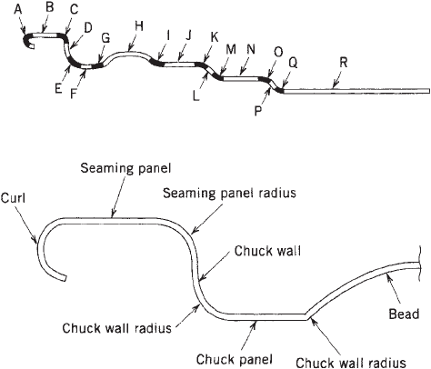
Food cans are expected to have tightly drawn-in ends.
A can with swelled ends or with metal feeling springy
or loose is not merchantable. Consumers associate such
appearances with spoiled contents. Gases produced by
microbial action can, indeed, cause such appearances. It
is also important to remove air from food cans to retard
adverse internal chemical reactions. Therefore, end units
must be properly engineered to cope with their many
environments. They must act as diaphragms that expand
during thermal processing and return to their tight
drawn-in appearance when a vacuum develops during
cooling. The necessary strength is built into the end units
by the use of adequate plate materials and design of end
profile (see Figure 1).
Food ends are either profiled structures requiring a
mechanical means for opening or designed with scores for
easy opening. Since the introduction of the easy-opening/
convenience end in the mid-1960s, a broad variety of
products have been packaged in cans with this feature.
These easily removed ends are available in various
diameters, metals, coatings, and configurations to meet
product needs. Units can be removed as a whole with
separation occurring around the perimeter of the end or
only a portion of the top can be removed. For those
products where consumer protection is desired, easy open-
ing ends can be provided with safety features.
Ends used for carbonated beverages and aerosol pro-
ducts and those used for noncarbonated beverages packed
using liquid-nitrogen pressurization, need little or no
vacuum accommodation but rather resistance to high
internal pressure. An end unit will permanently distort
or buckle when the internal pressure exceeds its capabil-
ity. This also renders the can unmerchantable because the
distortion could affect the double-seam integrity.
Cans with inadequate body strength will panel because
of internal vacuum or collapse under axial load conditions.
A panel is the inward collapse of the body wall because
of pressure differential. The condition may appear as a
single segment, many flat segments, or panels that de-
velop around the circumference of the cylindrical can body.
Axial load is the vertical pressure that a packed container
will be subject to during warehousing and shipping. The
axial load capacity of a can is greatest when the cylinder
wall is in no way deformed. A casual dent or designed
structure that breaks the integrity of the straight cylinder
will, in most cases, reduce the axial load capability of the
container. Panel resistance and axial load capability are
direct functions of the metal specification.
Panel resistance can be enhanced by the fabrication of
beads in the body wall. This, in effect, produces shorter
can segments that are more resistant to paneling.
However, such beads predispose the container to early
axial load failure. The deeper the bead is, the greater the
paneling resistance but the greater the reduction in axial
load capability. Many shallow beads can provide addi-
tional paneling resistance with less reduction in axial
load capability, but labeling problems are often associated
with cans with such bead configurations. Consequently,
there are many bead designs and arrangements, all
of which are attempts to meet certain performance
criteria (7).
The steel container with proper material and struc-
tural specifications possesses, within limits, good abuse
resistance. Excess abuse causes obvious damage, and
severely dented cans are unacceptable in the marketing
of canned products. Insidious events run parallel with
excessive abuse. The double seams may flex momentarily,
permitting an equally short-term interruption of the
hermetic seal. Under some unsatisfactory conditions,
this lapse can permit the entrance of micro-organisms
that cause spoilage. This leakage can also admit air that
accelerates adverse chemical reactions within the con-
tainer. Many cans that show some level of damage are
in the food distribution chain, and the safety of using
such products is frequently questioned. To prohibit the
sale of all containers that have insignificant amounts of
damage would be a waste of large amounts of acceptable
food (8).
Figure 1. End profiles (A—curl, B—seaming panel, C—steam-
ing panel radius, D—chuck wall, E—chuck wall radius, F—chuck
panel, G—chuck panel radius, H—bead, I—bead-edge radius, J—
first expansion panel, K—first expansion panel radius, L—first
expansion panel step, M—first expansion panel step radius, N—
second expansion panel, O—second expansion panel radius, P—
second expansion panel step, Q—second expansion panel step
radius, R—center expansion panel).
CANS, STEEL 209
CAN CORROSION
The steel container is not chemically inert and, therefore,
can react with its environment and its contents. Steel’s
major ingredient, iron, is a chemically active metal that
readily takes a part in reactions that involve water,
oxygen, acids, and a host of other elements and com-
pounds that can participate in oxidation reduction reac-
tions (see the Cans, corrosion article).
The application of tin to the surface of sheet signifi-
cantly increases the corrosion resistance of steel. Never-
theless, the potential for corrosion attack persists.
Although numerous modifying factors produce varied
patterns of attack, the chemical fundamentals for oxida-
tive corrosion are the same. The basic requirements are
always (a) differences in potential between adjacent areas
on an exposed metallic surface to provide anodes and
cathodes, (b) moisture to provide an electrolyte, (c) a
corroding agent to be reduced at the cathode, and (d) an
electrical path in the metal for electron flow from anodes
to cathodes.
Under normal conditions, tin forms the anode of the
couple, going into solution at an extremely slow rate and
thus providing protection to the canned food. Under some
conditions, iron forms the anode with resultant failure
because of perforations or the development of hydrogen
and subsequent swelled cans (hydrogen springers). Under
other conditions, as when depolarizing or oxidizing agents
(i.e., nitrates) are present, the removal of tin will be
greatly accelerated with a consequent significant reduc-
tion in shelf life. Hydrogen is formed by the following two
distinct processes: (a) at exposed steel areas that are
protected cathodically by the tin–steel couple current
and (b) as the steel corrodes, either because it is not
completely protected by the tin or after the tin has been
consumed. When perforations occur, they are usually the
result of the same process in which hydrogen is developed
except the steel is consumed in a localized area (9–11).
PRODUCT COMPATIBILITY
Products can be loosely categorized in terms of their
susceptibility to chemical reaction with the can. Oils and
fatty products seldom react with the metal surface of can
interiors. However, when small quantities of moisture are
present, either by design or accident, adverse reactions
can develop. Highly alkaline products, usually nonfoods,
will rapidly strip off tin or organic coatings but will not
corrode the base steel. Acid products are corrosive, and
highly colored acid foods and beverages are also suscep-
tible to color reduction or bleaching, because of the reac-
tion of the product with tin.
In this regard, when tin is exposed to some food
products, a bleaching action occurs. Although this is
objectionable with many products, such as the red fruits,
and is avoided by the use of a suitable can lining, this
bleaching action is desirable in certain instances. This is
particularly true with the lighter-colored products such as
grapefruit juice and grapefruit segments and sauerkraut.
A slight bleaching action keeps the color light and
compensates for the normal darkening effect, which may
result from the processing or sterilization. Peaches and
pears packed in cans completely enameled inside will be
somewhat darker in color and slightly different in flavor
than if packed in nonenameled plain tin cans. Although
some individuals may prefer peaches packed in all enam-
eled cans, it is doubtful that such cans will be produced
under current conditions because the presence of an
appreciable area of plain tin greatly increases the shelf
life of this canned product.
Foods with pHW4.6 often have sulfur-bearing consti-
tuents (e.g., protein) and react with both tin and iron. This
has been recognized as a problem for as long as such
products have been canned, and the cause has been sought
by many investigators. These low-acid foods form a dark
staining of the tin surface and react with the iron to form a
black deposit that adheres to both the can interior and the
food product or can cause a general graying of the food
product and liquor. This is often referred to as black
sulfide discoloration or sulfide black. It can be unsightly
but is harmless. Although sometimes exclusively a can
headspace phenomenon, any interior container surface
can be affected. Also, the black sulfide discoloration con-
dition generally occurs during or immediately following
heat processing, but occasionally it develops during sto-
rage. It is believed to be an interaction of the volatile
constituents from the food product and/or oxidation–
reduction agents in the food product with an oxidized
form of iron from the tinplate. The staining of the tinplate
is not part of this reaction (13, 14).
Although tin sulfide staining and black sulfide disco-
loration is harmless from a product standpoint and has
no detrimental effect on container or product shelf life,
it has been found to be objectionable from an aesthetic
standpoint.
In addition to container and product appearances, some
food products and beverages are highly sensitive to off-
flavors caused by exposure to can metals (12).
CAN METAL
The term ‘‘tin can’’ is somewhat of a misnomer, because tin
cans are made of steel sheets that have either no tin or
coated with a thin film of tin. The steel products commonly
produced for container components have a theoretical
thickness ranging from 0.0050 to 0.0149 in. (0.127 to
0.378 mm) expressed as weights per base box* of 45–
135 lb. Depending on end use, the plate (blackplate) can
be processed by the electrolytic deposition of metallic
chromium and chromium oxides and coated with a lubri-
cating film (tin-free steel) or coated with tin by electro-
deposition.
Improvements in electrolytic
tinplate, since its
commercial introduction in 1937, have increased both its
* Base weight—approximate thickness in pounds per base box:
(base weight 0.00011 = theoretical thickness). Base box—unit of
area: 112 sheets, 14 in. 20 in. = 31,360 in.
2
(217.78 ft
2
); dimen-
sions in increments of 1/16 in.
Package: 112 sheets of any dimensions. Number of base boxes in a
package: use ratio tables (ASTM A623) or L(in.) W(in.) 112 =
31,360. Number of base boxes in a coil: L(in.) W(in.) = 31,360.
210 CANS, STEEL
versatility and uniformity of performance. Electrolytic
plate has entirely replaced hot-dipped plate in present-
day cans. The result of these changes/improvements has
allowed for reductions in tin coating weights. Tin plate
carries a coating of tin that may vary from 0.000015 to
0.000100 in. in thickness, depending on the grade. Differ-
ential coated electrolytic tinplate, with different coating
weights of tin on each side of the steel baseplate, has been
used commercially since 1951. Containers made of differ-
ential coated tinplate have an inside tin coating of
sufficient thickness to withstand the corrosive attack of
processed foods and an outside coating adequate to with-
stand the rigors of processing and atmospheric conditions.
The thickness of tin coating is designated by the total
amount of tin used on coating one base box of plate. For
example, #25 plate is electrolytic tinplate on which 0.25 lb
of tin was electroplated on one base box, covering both
sides of the sheet. Thus, the coating on one side of the
sheet is one half that amount of tin, or 0.125 lb.
For structural integrity, base weight or gauge thickness
is a prime consideration, but any increment of base weight
is an increment in container cost. Often, the temper or
design of can components can provide added strength
without the need to add base weight. The chemistry and
general metallurgy of the steel plate has considerable
influence on the performance of steel containers. Before
the advent of continuously annealed and cold-rolled dou-
ble-reduced steel plate, which influence plate stiffness or
temper, it was necessary to add ingredients to the steel to
produce high tempers. Temper as applied to tin-mill
products is the summation of inter-related mechanical
properties such as elasticity, stiffness, springiness, and
fluting tendency. During the development of the use of
cold-reduced steel for mill products, the fabricators deter-
mined that various steel compositions and degrees of
hardness in the base metal would permit the production
of containers for a wider variety of products. Although
there are certain limitations to the Rockwell hardness
test,
w
it has been adopted as an industry standard because
of its simplicity and overall good correlation with fabrica-
tion requirements. As a result, ranges of Rockwell hard-
ness were developed to guide the steel manufacturers, and
these Rockwell hardness ranges have become accepted as
temper ranges.
Rephosphorized steel was necessary to fabricate beer
can ends with sufficient buckling resistance. When the
market opened for canned carbonated soft drinks, repho-
sphorized steel was not acceptable because of the corrosive
nature of soft drinks and the high susceptibility of this
plate to corrosion. Test pack experience indicated that
some could perforate the endplate in 4–6 weeks. The
availability of continuously annealed plate without the
corrosion sensitivity properties of rephosphorized steel
permitted the canning of soft drinks. It was still necessary
to use heavier base weight material for the high-carbona-
tion drinks. The added stiffness afforded by cold-rolled
double reduced plate permitted the canning of all soft
drinks with carbonation ranging from 1.0 to 4.5 volumes
in cans with the same basis-weight ends. These same
economies have been applied to other products where
container fabrication could be adapted to the degree of
stiffness characteristic of this plate (14).
CAN FABRICATION
One who is not associated with the container industry
seldom realizes that the manufacture of cans is classed as
one of the most mechanized industries, and in addition to
the large amount of automatic equipment used, the speed
at which cans are made no doubt rates among the faster
automatic operations (see the Metals Cans, Fabrication
article).
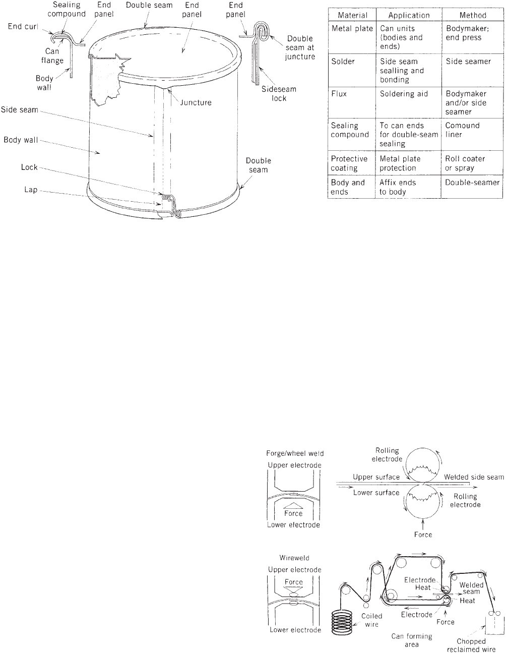
The most common type of steel can produced today are
three-piece cans that consist of a body with a welded or
soldered side seam in conjunction with two end compo-
nents (see Figure 2). Another popular structure is the
two-piece can, which is produced by either a single-draw,
draw-redraw (DRD), or drawn-and-iron (D & I) process.
Some limited quantities of cemented side-seam cans are
produced for dry and nonthermal processed type products.
Most three-piece tinplate cans currently made have
wire-welded side seams. The traditional soldered can is
now in the minority and only is used for irregular-type
meat cans and specialty cans. The solder used in canmak-
ing is now generally composed of tin and silver. In July
1995 the U.S. Food and Drug Administration (FDA) has
issued a final rule prohibiting the use of lead solder in the
manufacturing of food cans, including imported products.
The tin/silver solder is categorized as a soft solder and
has a relatively low melting point, usually below 4501F,
(2321C). Tinplate cans are easily soldered because the tin
solder alloy readily fuses with the tin on the surface of the
steel. In addition to providing a hermetic seal, solder also
contributes to the mechanical strength of the seam by
forming a metallurgical bond with the tin plate. Solder
also has a certain amount of ductility and can be plasti-
cally deformed within certain limits. This characteristic
permits the soldered laps of the body to be flanged and
then incorporated into the double-seaming process. The
speed of the can manufacturing line, the temperature of
the molten solder, and the length of cooling all play an
important role in good soldering operations. The soldered
side seam can has been replaced for many can structures
with an electrical resistance—welded seam. Benefits in-
clude a clean compact process and a much narrower weld
area, which allows virtually wrap-around decoration and
greater integrity, particularly for seaming-on of ends,
because there is much less metal overlap thickness at
the weld compared with the soldered lock and lap seam
employed on soldered cans. The welding unit is easily
integrated and ancillary equipment used on solder body-
maker lines.
Two reliable welding systems were developed and used
commercially: The forge–wheel welding system developed
w
A device used to measure the surface hardness of canmaking
plate. A 1/16-in.-diameter ball penetrator is impressed into the
plate surface with a 30-kg load. The measurement expressed as a
Rockwell 30T reading, is inversely proportional to the penetra-
tion. An arbitrary scale is used to convert Rockwell readings into
plate temper values. The stiffness increases from T-1 to T-6.
CANS, STEEL 211
by Continental Can Company, and the wire weld system
was developed by Soudronic AG (15, 16). Both are resis-
tance-welding systems and variations of a forge weld
(see Figure 3). The materials to be welded together are
heated by an electric current passing through the materi-
als. The resistance of the overlapped side seam produces
the required welding heat. To obtain a weld, the heated
material must be pressed together or clamped. This
clamping capability is provided by wheels in the welding
process. Because welded seams are basically lap seams, a
raw edge exists, which generally requires a side-seam
stripe coating application to minimize metal exposure.
For economic reasons, the forge-wheel welding process
is no longer a viable commercial operation. Such forge-
welded cans used tin-free steel (TFS) plate and started
with the grinding of the body blank edges to remove oxide
and chromium to ensure acceptable welds. After blanks
are formed into cylinders, the edges are tack welded
together to produce an overlap, and the seam is made by
rolling electrodes that weld the interior and exterior of the
lap simultaneously.
In the wire welded operation that is used extensively
today, the welding process consists of passing the seam
with a small overlap between two electrode wheels over
which runs a copper wire. The use of copper wire as an
intermediate electrode is necessary to remove the small
amount of tin picked up from the tinplate during the
welding process, which would otherwise reduce the weld-
ing efficiency. A constantly renewable copper surface is
presented to the weld area. To obtain a weld, the heated
material is pressed together or clamped by wheels in the
welding process (see Figure 3).
Another innovation has been the introduction in the
early 1960s of the seamless two-piece can (integral
base and body, with one customer end). Metal forming
technology has been used to produce these cans from a flat
sheet. Drawn and ironed cans employ tinplate and are
manufactured by first drawing a shallow cup and then
extending the sidewalls by thinning the metal between
two concentric annular dies in an ‘‘ironing’’ process. This
results in a can with a normal base thickness and thinner
walls, and it is economical in materials usage. The capital
cost of D&I canmaking plants is high, but unit costs are
the lowest of all container types if the throughput is
sufficiently great. Because of the thin walls, body beading
is essential to maintain rigidity for vacuum-packed food
cans. The other two-piece can achieves final can dimen-
sions through a series of consecutive drawing operations.
In these DRD cans, the thickness of the bottom end and
the side walls is largely the same and there is not the same
opportunity for saving on metal. Unlike the D&I can,
Figure 2. Double-seam three-piece can.
Figure 3. Welding process.
212 CANS, STEEL
which uses tinplate and inside spray coatings, the DRD
can uses TFS-precoated sheet or coil plate.
Organic sealing materials have been used as side-seam
sealants mostly before the advent of the welded can. They
have been used in situations where soldered structures
were not compatible with the product, when special wrap-
around lithography is desired, and when tin-free steel is
used. For the most part, polyamides and organosols are
used as the basic resin of organic sealing materials. They
are normally used for a variety of can sizes, shapes, and
styles that are used for dry and nonfood products. How-
ever, a polyamide hot-melt adhesive has been successfully
used in oblong meat cans that are subjected to a high-
temperature thermal process.
Much consideration has been given to cost reductions of
the metal can. In conjunction with thinner gauge and
higher temper plates, the reduction of the can diameter of
the two-piece beverage cans in the area of the end unit has
reduced the cost of metal cans significantly. This body
diameter reduction is usually accomplished by a die neck-
ing-in process, which is performed prior to flanging. The
necking-in process tends to alter the can height, so careful
body cut edge and/or can trim diameter must be calculated
to afford these accommodations. With three-piece cans,
this necked-in structure can be fabricated on both ends;
however, it is done on only one end of two-piece cans used
for liquid-type products.
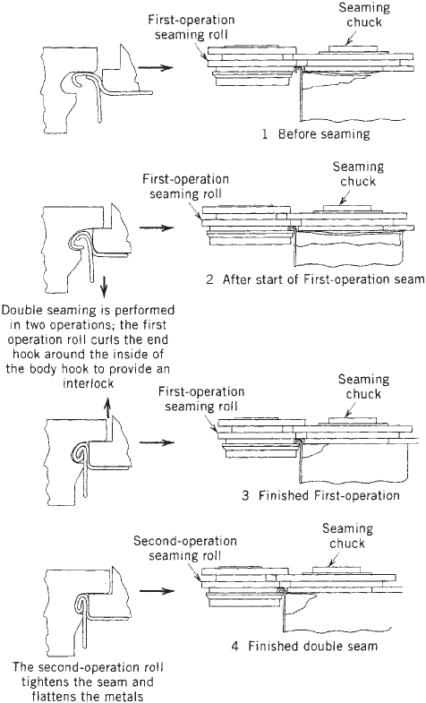
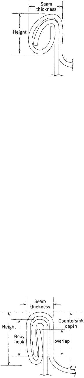
The popularity of steel cans has been in large measure
caused by the double seam’s ease of fabrication and robust
resistance to physical abuse. This seam structure is the
portion of a can that is formed by rolling the curled edge of
the end and the body together to produce a strong leak-
proof structure. This seam is normally formed by a set of
first and second operation seaming rolls while the end and
the can body are held together by a seaming chuck. The
first operation seaming roll forms the seam by interlock-
ing the curled edge of the end with the flange of the can
body. The second-operation seaming roll compresses the
formed seam to make a hermetic seal (Figures 4–6).
Because metal-to-metal contact does not produce good
sealing capability, a rubber-like material known as sealing
compound is applied to the loose end-unit seaming panel
that becomes engaged to the body flange to form the
double seam. This material acts like a sealing gasket.
Compound placement and compatibility with the product
are important in providing for a hermetic seal. End-
sealing compounds are generally one of two types: (a)
water base—rubber/water dispersions and (b) solvent
base—rubber/solvent dispersions.
COATINGS
Organic protective coatings are used as can linings to
provide the additional protection above that provided by
the metal substrate. These organic materials are applied
to a flat plate or a coil-coated plate and are cured by means
of continuous ovens. Spraying after complete or partial
fabrication is also done when low-metal-exposure cans are
required for aggressive-type products. It is desirable to use
can linings that possess a reasonable degree of latitude in
film weight and bake. The roller coating machines and the
spraying machines used to apply linings provide means
for close control of film weight. The films, of course, are
relatively thin, about 0.0001–0.0005 in. thick or with a
weight of 2–6 mg/in.
2
Control limits generally allow for
variation of 70.5 mg/in.
2
Can linings must be nontoxic, meet government stan-
dards, be free from odors and flavors, and be readily
applied and cured. They also must withstand the mechan-
ical operation of canmaking, must provide the required
barrier between canned product and metal, and finally
must be economical. Accelerated tests are used as screen-
ing or control tests, and evaluations under commercial
conditions are normally required before final approval of a
can lining is standardized. When required, product test
packs will be made and monitored over a period of time to
confirm that the coating material is compatible with the
intended product and/or container components.
Coatings accomplish several purposes. They make pos-
sible the use of less costly steels that permit the use of
Figure 4. Sequence of operations in seaming a can end onto a
can body.
CANS, STEEL 213
different types of tin-mill products in the can body and
ends. They protect the steel against corrosion and the
product from the steel and on the can exterior, minimize
rusting, and serve as a background to or improve adhesion
for lithography. Inorganic protective coatings that often
contain phosphates, chromates, or both are usually ap-
plied to tin-free steel at the tin mill to prevent rust and
provide a good surface for organic materials. If tin or iron
is detrimental to a product, then a suitable protective
coating can be applied. These coatings can prevent bleach-
ing discoloration by tin to dark pigments of foods such as
strawberries, blueberries, blackberries, and cherries. Also,
protective coatings can reduce the metal exposure for
metalsensitive products such as beer and certain soft
drinks. Other products would react with the unprotected
can interior to cause corrosion or cause discoloration of
both container and product. Finally, a protective coating
can mask unsightly discoloration of the can interior.
Currently, the major trend in coating technology is
toward waterborne coatings to replace conventional or-
ganic coatings. Typical organic coatings contain as much
as 70% solvents and are subject to stringent environmen-
tal restrictions. One answer is the aqueous coating, which
contains only a small amount of organic solvents and can
use the same coating and curing equipment. These aqu-
eous coatings, which were commercialized for food cans in
the early 1990s, exhibit the same good flow and leveling
characteristics as found with solvent-base coatings.
Metal exposure in the side seam area is a common
occurrence with all three-piece can structures, and a
special protective coating material (a ‘‘side stripe’’) is
sometimes applied to the inside and outside side seam
area by spray or roller, online, followed by curing. Most
stripes used are organic liquid materials, which provide
only minimal coverage. Polyester powder (thermoplastic)
electrostatic spray stripes give superior performance.
These types of stripe coating provide 100% side-seam
coverage, but they are more costly than liquid stripes.
However, powder stripes have poor heat resistance and
are not recommended for use in cans that will be subjected
to aseptic process conditions that employ super-heated
steam.
Organic protective coatings were first applied to can
interiors to protect the red fruit colors. Coatings used to
combat this problem were often called ‘‘regular’’ or ‘‘R-
enamels.’’ Now they are generally identified by a number,
letters, or a combination of numbers and letters.
If ordinary oleoresinous can linings are used for foods
containing appreciable quantities of protein such as corn,
peas, and fish, then a black tin sulfide stain will form
under the enamel; under certain conditions, black sulfide
discoloration will form at iron-exposed small scratches
and fractures. To minimize black sulfide discoloration,
oleoresinous enamels used for such products contain
about 6% of a fine-particle-size zinc oxide, which is added
for its chemical reactivity and not as a pigment. The
sulfides that form during the processing or heat steriliza-
tion of the protein-containing foods react with the zinc
oxide, which ‘‘de-zincs’’ and allows the formation of zinc
sulfide. Zinc sulfide is white and generally goes unnoticed.
Can linings containing zinc oxide were first developed for
corn cans and were called ‘‘corn enamels’’; their use was
soon extended to other products, and they were then called
‘‘C-enamels.’’
Sulfide staining appears as a brown or brownish blue
stain on the surface of the tin coating and cannot be
removed by rubbing. Sulfide staining occurs not only on
exposed tin surfaces but also in tin surfaces protected by
many of the enamels because the volatile sulfur com-
pounds involved can permeate certain types of enamel
coating. To prevent underfilm sulfide staining, enamels
impervious to volatile sulfur compounds are used where
possible. However, such enamels are not always compa-
tible with the product being packed, in which case it is
necessary to use a pigmented enamel that will either
inhibit or mask the sulfide staining. These methods of
inhibiting or masking sulfide staining are limited to their
application, because not all enamels combine satisfacto-
rily with a given pigment or additive.
Many coatings are now in use and being developed for
steel cans used for a variety of food and nonfood products.
Some of those materials, which are supplied by coating
suppliers to the application facility and are now being
used, include acrylic, alkyd, epoxy amine, epoxyphenolic,
oleoresinous, oleoresinous w/zinc oxide, phenolic, polybu-
tadiene, vinyl, and vinyl organosol. Each material has its
own unique performance characteristics with regard to its
application, fabrication, product compatibility, flavor and
odor, process resistance, and so on.
Figure 5. First operation.
Figure 6. Second operation.
214 CANS, STEEL
It has been apparent since the early days of canning
green vegetables that the bright green darkens as a result
of the required thermal process, that is, the bright green
chlorophyll undergoes a chemical change to an olive green
pheophytin. There have been several studies conducted
to inhibit this chemical change. They all demonstrate an
inhibition capability by using additives containing mag-
nesium ions and careful control of pH by the addition of
hydroxyl ions. All of these procedures cause some tough-
ening of the product, which probably discourages any
commercial pursuits. The Crown Cork and Seal Company,
Inc. has a patented process called ‘‘Veri-green,’’ which
incorporates additives to the product as well as the
protective coating. The materials added are specific for
particular products, and pretesting is necessary (17–21).
DECORATION
Decorative lithographic designs afford an external protec-
tive coating. The process of application is known as offset
lithography. Lithography is a printing process based on
the fact that oil and water do not mix. The decorative
design to be printed on the tinplate is etched onto a plate
known as a master plate in such a manner that the image
area to be printed is ink receptive, whereas the portion to
be blank is water receptive. A lithographic design is a
system or a series of coatings and inks printed on plate in
a particular sequence. The order of laydown is determined
by the purpose of the coat, the kind of coating or ink, and
the baking schedule for each coat or print. The print
process is usually carried out with sheet stock prior to
slitting into can body blanks or scroll shearing into the end
stock. The sequence and type of equipment used depends
on the design and the ultimate use of the can (see the
Decorating article).
With the advent of two-piece cans, less elaborate de-
signs are used on beer and soft-drink cans because it was
necessary to use presses that print completely fabricated
cans. The finishing varnishes are usually the external
protective coatings. They not only protect against corro-
sion but also must be rugged enough to resist scuffing and
abrasion.
For drawn-and-iron beaded food cans, the outside is
coated with a water-based colorless wash coat material.
After packing, the customer glues a paper label to the body
wall, which identifies the contents.
TECHNOLOGICAL DEVELOPMENTS
The steel can has grown despite competitive pressures.
During war years, tin and iron become controlled materi-
als, and other more available packaging materials usually
make inroads into the steel-can market. These same
constricting conditions often give rise to the development
of methods that reduce the consumption of the controlled
materials. During World War II, the electrolytic deposition
of tinplate was commercialized, which resulted in sub-
stantial reductions in tin consumption. Competition from
aluminum in the beverage-can business gave impetus to
pursue the use of tin-free steel to afford more favorable
economics. Successful cost reductions with no reduction in
performance, however, has been the cause for the contin-
ued growth of the steel can. The advent of cold-rolled,
double-reduced plate permitted significant reductions in
base weight. To accommodate the fabricating character-
istics of this material, new approaches in end manufacture
and double seaming had to be developed. Another direc-
tion to cost reduction was to reduce materials usage. This
was accomplished by using smaller-diameter ends and
necking-in the can bodies to accommodate the reduced-
diameter ends. This saving can be directed to one or both
ends on three-piece cans.
The use of convenience features has been an important
stimulus to the growth of steel cans. Key-opening lids and
rip strips have been part of fish and meat cans for
generations. This style was also standard for coffee and
shortening cans, but economic pressures caused a change
to less expensive open-top food cans. Development of the
integral rivet and scored end solved many can opening
problems, particularly in the beverage and snack-food
businesses.
There have been dramatic developments in the overall
operation of can-making plants with increasing use of
automated procedures and computerized control systems
and techniques to optimize production processes. There
has been a reduction in the number of operatives, but the
working conditions of those remaining have been greatly
improved. These new developments are ensuring that the
can remains cost effective and reliable.
With thinner gauge plates and faster production
speeds, can-making equipment has become increasingly
precise in its operations. Reliability is all important, and
quality-control measures have been put in place at every
critical step to ensure container integrity. These include
gauge measurements, weld monitors, and leak testing.
Also there is more use of sophisticated statistical control
charts, statistical analysis, and design of experiments to
solve complex problems, particularly in manufacturing
and technical areas.
There have been innovations in coatings technology
such as the introduction of waterborne coatings, coil coat-
ing, powder coating in electrostatic spray systems, and
organic resins that are deposited electrophoretically on
the can components from an aqueous solution. Increasing
use is being made of the new ultraviolet systems, which
dry-sheet coatings and inks in seconds at ambient tem-
peratures
. Also,
laminate polymer films have been intro-
duced to compete with liquid organic coatings to metal
substrates that are used for can components.
Early in the 1970s, health authorities and the FDA
became concerned about the increment, if any, of lead and
other heavy metals that are picked up by foods packed in
soldered cans. The manufacturers of baby foods and baby-
formula foods or ingredients, such as evaporated milk,
were the first to be asked to reduce the level of lead in
their canned products. Better care during soldering opera-
tions and ventilation resulted in major reductions but did
not eliminate all lead in the respective foods. Currently all
soldered cans being produced are using lead-free solders.
Also, the introduction of the three-piece welded and
CANS, STEEL 215
two-piece cans have virtually eliminated the concern of
lead contamination (22).
BIBLIOGRAPHY
1. Canned Foods, Principles of Thermal Process Control, Acid-
ification and Container Closure Evaluation, 3rd edition, Food
Processors Institute, Washington, DC, 1980, pp. 7, 141.
2. American Can Company, Canned Food Reference Manual,
McGraw-Hill, New York, 1947, pp. 25–29.
3. S. C. Prescott and B. E. Proctor, Food Technol. 4, 387 (1937).
4. E. J. Cameron and J. R. Esty, Canned Foods in Human
Nutrition, National Canners Association (NFPA), Washing-
ton, DC, 1950.
5. G. A. Hadaby, R. W. Lewis, and C. R. Ray, J. Food Sci. 47, 263–
266 (1982).
6. B. K. Watt and A. L. Merrill, ‘‘Composition of Foods—Raw,
Processed, Prepared’’ in U.S. Department of Agriculture
Handbook, 8th edition, Washington, DC, 1963.
7. Crown Cork and Seal Company, Inc., unpublished information.
8. Safety of Damaged Can Food Containers, Bulletin 38-L, Na-
tional Canners Association (NFPA), Washington, DC, 1975.
9. R. R. Hartwell, Adv. Food Rev. 3, 328 (1951).
10. R. P. Farrow, J. E. Charboneau, and N. T. Loe, Research
Program on Internal Can Corrosion, National Canners Asso-
ciation (NFPA), Washington, DC, 1969.
11. N. H. Strodtz and R. E. Henry, Food Technol. 8, 93 (1954).
12. J. S. Blair and W. N. Jensen, ‘‘Mechanism of the Formation of
Sulfide Black in Non Acid Canned Products,’’ paper presented
on June 12, 1962 at the 22nd Annual Meeting of Food
Technologists, Miami Beach, FL.
13. J. E. Chabonneau, ‘‘The Cause and Prevention of ‘Sulfide
Black,’’’ in Canned Foods, National Food Processors Research
Foundation, Washington, DC, 1978.
14. ‘‘Tin Mill Products’’ in Steel Products Manual, American Iron
and Steel Institute, New York, 1968.
15. U.S. Pat. 3,834,010 (Sept. 10, 1974), R. W. Wolfe and R. E.
Carlson (to Continental Can Co.).
16. Soudronic AG, CH-8962, Bergdietikon, Switzerland.
17. F. A. Lee, Basic Food Chemistry, Avi Publishing, Westport,
CT, 1975, pp. 163–165.
18. U.S. Pat. 2,189,774 (Feb. 13, 1940), J. S. Blair (to American
Can Co.).
19. U.S. Pat. 2,305,643 (Jan. 5, 1942), A. E. Stevenson and K. Y.
Swartz (to Continental Can Co.).
20. U.S. Pat. 2,875,071 (May 18, 1955), Malecki and co-workers
(to Patent Protection Corp.).
21. U.S. Pat. 4,473,591 (Sept. 25, 1984), W. P. Segner and co-
workers (to Continental Can Co.).
22. Bakker, ‘‘The Competitive Position of the Steel Can’’ in
Technology Forecast, Avi Publishing, Westport, CT, 1984.
CAPPING MACHINERY
In categorizing capping machinery that applies closures to
bottles and jars, the best place to start is with the closure
itself (see Closures). The different types of machinery for
applying these closures have features in common (e.g.,
straight-line vs. rotary). This article provides a basic
description of machinery used for continuous-thread
(CT) closures, vacuum closures, roll-on closures, and
presson closures.
CAPPERS FOR CT CLOSURES
There are four basic types of capper for CT closures, which
are as follows: hand cappers and cap tighteners; single-
spindle (single-head), intermittent-motion cappers;
straight-line, continuous-motion cappers; and rotary con-
tinuous-motion cappers.
Torque Control. All automatic cappers apply the clo-
sures mechanically, but they differ in their approaches to
torque control. In general, torque control is achieved with
chucks or spinning wheels (rollers). Straight-line, contin-
uous-motion cappers generally control torque mechani-
cally, but all other types use either pneumatic or
mechanical means, or combinations thereof.
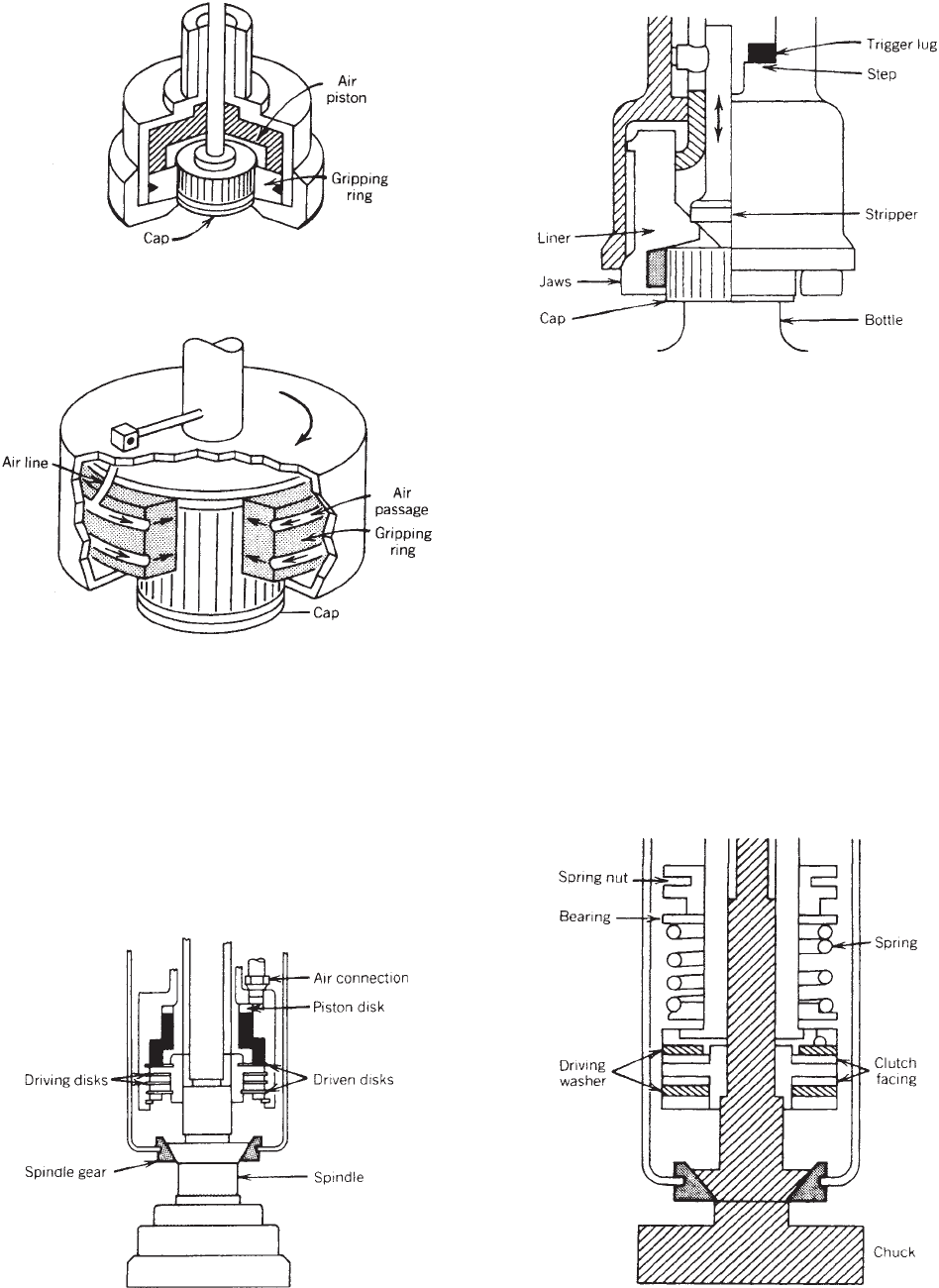
A pneumatic chuck contains a round flexible ring with
a hole in the center (1). The cap enters the hole when the
ring is in its relaxed state. When air pressure is applied,
the ring compresses and grips and holds the cap while it is
moved to the bottles and screwed on. The air pressure may
be applied by the downward movement of an air piston, or
it may be directed into the space between the ring and the
wall of the chuck (see Figure 1).
The amount of torque is controlled by a pneumatic
clutch operated by pressure from low-level pneumatic
lines (see Figure 2). It contains two or more sets of disks
that are pressed against each other when air is applied,
which connects the chuck and drive shaft. When the cap is
screwed on to the point that the torque being applied
equals the force being applied to the disks by air pressure,
the disks start to slip and the drive shaft is disconnected.
A typical mechanical chuck has jaws that close around
the skirt of the cap to maintain a grip until the closure
application is complete (see Figure 3). A mechanical chuck
can be controlled by a pneumatic clutch, but it also can be
controlled by a spring-loaded clutch or a barrel cam. The
pneumatic clutch is similar to the clutch used for a
pneumatic chuck. A spring-loaded clutch (see Figure 4)
uses a spring to disconnect the chuck from the power
source when the preset amount of torsion has been applied
to the cap (1). Torque can be increased by compressing the
spring by screwing down the collar on top of the spring; it
can be decreased by moving the collar to loosen the spring.
The chuck opens to release the bottle when the torsion on
the cap matches the torsion on the spring.
On some capping machines, the heads are raised and
lowered by a follower riding on a barrel cam (see Figure 5).
Manufacturers of capping machinery have different ap-
proaches to torque control based on the principles or
combinations thereof, described above.
Hand Cappers/Cap Tighteners. With operating speeds of
up to 20 caps/min, hand cappers are used for low
216 CAPPING MACHINERY
production volumes or unusual caps. Hand cappers work
with some kind of handheld chuck. Cap tighteners, a step
up in automation, are useful for pump and trigger-cap
applications, retorqueing after induction sealing, and
short production runs in general.
Single-Spindle, Intermittent-Motion Cappers. Using either
pneumatic or mechanical torque control, these cappers can
theoretically apply up to 60 caps/min, and they are useful
for relatively short production runs. Their versatility is
limited by the intermittent motion that would tend to cause
spillage from widemouth containers.
Straight-Line, Continuous-Motion Cappers. On these ma-
chines, torque-control clutches are built into multiple
spindles that turn the rollers (disks) that apply the caps
(see Figure 6). In contrast to the single-spindle cappers,
the bottles never stop and the speed of capping is limited
only by the speed of the conveyor. The capability of the
machines has traditionally been quoted as 60–300 caps/
min (in contrast to rotary machines that can be more than
twice as fast), but by using multiple spindles, speeds can
be increased greatly; for example, with eight spindles at
four stations, production can be as high as 600/min or
more, depending on the size of the cap and the container.
Figure 1. Pneumatic chuck (1).
Figure 2. Pneumatic clutch (1).
Figure 3. Mechanical chuck with jaws (1).
Figure 4. Spring-loaded clutch (1).
CAPPING MACHINERY 217