Yao N. Focused Ion Beam Systems: Basics and Applications
Подождите немного. Документ загружается.

lamellae to be prepared along its length relatively quickly (Figure 8.2(b)). The
most widely used method to prepare a slice is hand polishing and as this can
be readily combined with the other methods and only requires polishing
pastes or sheets, it is outlined in detail below.
The first step in preparing a slice by hand polishing consists of identifying the
ROI under an optical microscope. If it is too small to be observed, FIB milling
Ion
beam
Tilting sample
+tilt
–tilt
Line
milling
(e)
Tapered
sample
(b)
TEM lamellae
Dice
(a)
(c)
(d)
TEM grid
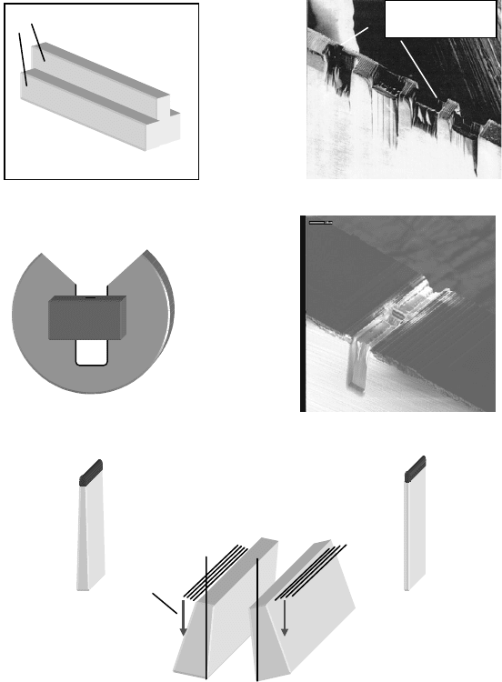
Figure 8.2 (a) T-shaped slice prepared by dicing four cuts, (b) an SE image of
a tripod polished slice into which numerous TEM lamellae have been milled,
(c) schematic of a slice mounted on a U-shaped TEM grid, (d) SE image of a
finished H-bar sample ready for TEM, and (e) schematic of the tilting of a
sample into the ion beam to produce a lamella with parallel sidewalls.
Focused ion beam systems218
or Pt deposition can be used to render it visible. An area of approximately
2.5 mm
2
surrounding the ROI is then cleaved, cut, or polished. This is then
mounted, using wax, onto a microscope slide such that it protrudes over the
slice’s edge and is polished using diamond paste or Al
2
O
3
sheets with a series of
polishing grades (30 m mdownto0.5m m). A good support for the Al
2
O
3
sheets
is a wet glass pane as this keeps them flat and prevents them slipping. During
polishing the sample is repeatedly examined under an optical microscope and
the polishing is stopped when the ROI is to within 30–50 mm of the edge of the
slide. The slide is then heated on a hot plate to melt the wax and the sample is
removed and remounted with the other side protruding over the edge of the
glass slide. It is then polished again until the slice is 50–100 m m wide. Typically,
this hand polishing takes about two to three hours but the exact time depends
on the hardness of the material and the initial dimensions of the square. The
slice is then removed from the slide (again by melting the wax), washed in
acetone to remove any residual wax and fixed using conductive paint to a
TEM slot grid which has been cut in half (Figure 8. 2(c)). The sample is then
mounted in a suitable clamp and placed into the FIB or FIB/SEM system
chamber with the top of the slice perpendicular to the FIB.
In the FIB or FIB/SEM system, the ROI is identified and a 1.5 mm wide
and 1–3 m m thick Pt strap is deposited over it using ion beam assisted metal
deposition [ 36,37]. This planarizes the surface and prevents rounding and
milling of the top of the sample during FIB milling. If the sample is not
planarized, height steps can lead to striations in the face of a cross section
(the ‘‘curtain effect’’) due to changes in the sputter yield [38,39]. (The
required thickness of the Pt deposited is dependent on the ion beam profile
and the topography of the surface.) If the deposited Pt strap obscures the
ROI, lines for positioning the TEM lamella during the FIB milling can be
milled outside the area where the Pt will be deposited.
After depositing the Pt strap, two trenches are milled at a distance of
1.5 mm from each side of the Pt out to the edges of the slice, using a large
beam current (2 nA to 20 nA) and by scanning the ion beam in a serpentine
pattern. The exact dimensions of the trenches (and the Pt strap) are dictated
by time constraints, the size of the feature or ROI, and the angles of tilt or
rotation required in the TEM (see Section 8.2.4).
Having milled the trenches the remaining material between them is then
thinned to create an electron transparent lamella. For this step the magnitude
of the ion beam current is reduced to 1000 pA or 500 pA (to decrease the spot
size to give better control of the subsequent thinning/milling steps). In
addition, the milling regime is changed. The ion beam is scanned in lines and
is moved inwards in steps of half a beam diameter; a process frequently
Preparation for physico-chemical analysis 219
referred to as FIB polishing. This decreases the amount of material
redeposited onto the sides of the lamella and reduces the probability of
accidentally milling the lamella due to ion beam or stage drifts. As the sputter
rate is higher when milling at the edge of a step than when milling into a flat
surface the ‘‘depth’’ to which the lines are milled should be at least 30% less
than the ‘‘depth’’ that the trenches were milled, if the same milling para-
meters are used (i.e., beam overlap, sputter yields, and dwell times). Dis-
cussions on the effect of different milling regimes on the sputter rates can be
found in the papers by Ghandhi and Orloff [40] and Santamore et al.[41].
Furthermore, as a result of milling by the tails of the ion beam distribution
and the increase in the sputter yields as the angle of incidence of the ion beam
to a surface increases, the sidewalls of the remaining material are tapered
(Figure 8.2(e)). (For a mathematical description of the evolution of this taper
see Boxleitner [42].) If a lamella with parallel sidewalls is required, for
example for quantitative chemical analysis (and throughout the rest of the
chapter it is assumed that this is always the case), this taper can be removed
by tilting the sample into the ion beam while it is being thinned using the line
milling procedure (Figure 8.2(e)). The tilt angles used have ranged from 1
to
4
, depending on the material, the magnitude of the beam current, and the
depth of the lamella being milled.
Once the remaining material is approximately 500 nm the magnitude of the
ion beam is further reduced to 300 or 100 pA (again to produce a smaller spot
size) and it is thinned, using the line milling and tilting procedure, until it is
approximately 100 nm thick. Some materials are under intrinsic stress and as
such may buckle during the final thinning to electron transparency. Walker
[43] showed that a cut made at the side edge of such lamella can relieve the
stress, resulting in the straightening of the lamella and enabling it to be
further thinned to electron transparency.
During the final thinning, if a single ion beam system is being used the
sample is repeatedly imaged and the real-time SE signal is monitored for any
sudden increases in intensity to ensure that neither beam nor stage drifts
cause the lamella to be milled. If an FIB/SEM system is being used the
electron beam can be used to monitor and end the thinning once the thick-
ness of the remaining Pt has been reduced to a few hundred nanometers.
Techniques to thin the lamellae below 100 nm are discussed in Section 8.6.3.
A finished sample, through some CMOS transistor gates, ready for TEM, is
shown in Figure 8.2(d).
As FIB milling is relatively slow to remove large volumes of material it is
not practical to use it to prepare lamellae of features that are hundreds of
micrometers beneath the surface of a sample. To mill away a trench that is
Focused ion beam systems220
100 mm deep, 50 m m wide, and 60 m m long would take over 8 hours when
using a beam current of 20 nA. To overcome this limitation to enable
lamellae to be prepared from crack tips located hundreds of micrometers
beneath the surface of the sample both Deshais et al. [44] and Huang et al.
[45] combined the H-bar technique with BIB milling. They both used
conventional dicing and polishing to prepare the slices for the H-bar
technique, but then used BIB milling to sputter the slice to decrease the
distance of the crack tips from the surface (which also reduced the width of
the slice) before the sample was placed in the FIB system. Mechanical
polishing to the crack tips was not used as there were concerns that this
might affect the integrity of the cracks.
8.2.2 Ex-situ lift-out
The ex-situ lift-out technique was first described by Overwijk et al. [46] and
involves cutting a lamella free from the sample, lifting it out, and placing it
onto a TEM support grid using a needle, micromanipulator, and optical
microscope. From the mid 1990s until recently (circa 2005) this has been the
main technique used.
In this technique, the whole of the sample (if it is of suitable dimensions,
otherwise it has to be diced or polished) is placed in the FIB chamber. As
with the H-bar technique, the ROI is identified and coated with a Pt strap.
Staircase-shaped cuts, positioned 1.5 m m from either side of the Pt strap, are
then milled using a large beam current (2 to 20 nA) (Figure 8.3(a)). Staircase-
shaped cuts rather than rectangular ones are milled to reduce the milling time
as in the subsequent steps the slice/lamella is only ever milled/viewed at 45
.
The staircase cuts are typically milled 15–20 mm wide and 8–12 m m deep. If
the dimensions are much smaller than this, it becomes difficult to lift out the
lamella with the needle and micromanipulator.
The material between the staircase cuts is then thinned to approximately
300 nm by using the line milling and tilting procedure, outlined for the H-bar
technique. The sample is next tilted to 45
and the base and side edges (one
completely and the other only 80% along its length) of the slice/lamella are
milled through (Figure 8.3(b)). The changes in intensity of the SE signal
during the milling can be used to determine when the lamella has been cut
through. It is very important that the base and sidewalls are completely cut
through otherwise the lamella can not be lifted out from the FIB cuts. To
ensure this the box used to cut through the base should be positioned at least
1 mm above the base of the slice and the depth to which it is milled should be
Preparation for physico-chemical analysis 221
at least twice the thickness of the slice. (As the box is milled at 45
redepo-
sition onto its sidewalls will occur which reduces the sputter rate.) In a single
beam system if there is any uncertainty as to whether the slice/lamella has
been cut through the sample should be rotated by 180
and the opposite side
of the slice/lamella inspected for the cuts. If using an FIB/SEM system it is
not necessary to rotate the sample. Once the FIB has cut through the slice/
lamella it will mill a U-shaped cut into the opposite staircase which can be
seen by electron beam imaging as this is perpendicular to the surface of the
sample (see Figure 8.5(c)).
(c)
(a)
Pt
Staircase cuts
(b)
Cuts to the side
wall and base
(d)
TEM lamella
(f)
TEM lamella
(e)
TEM lamella
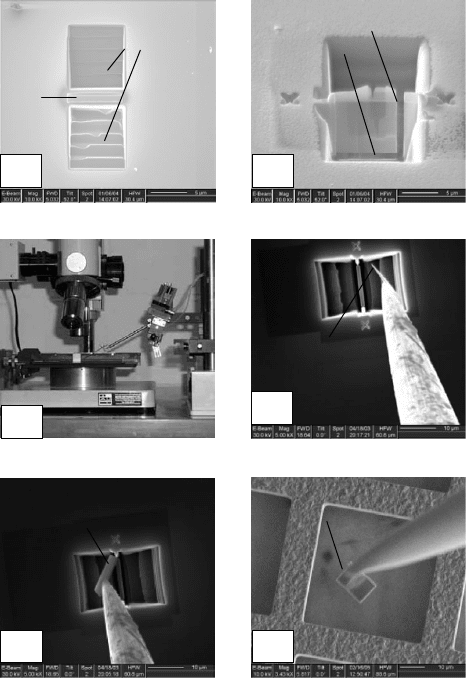
Figure 8.3 SE images of (a) staircase cuts milled on either side of the Pt,
(b) sample tilted to 45
whose sidewal ls and base have been cut, (c) an
ex-situ micromanipulator and optical microscope, (d, e) a needle being
pushed against a lamella, and (f) a lamella being placed onto a carbon
support membrane.
Focused ion beam systems222
The sample is then tilted back to zero degrees, and again the tilting and line
milling procedure and a beam current of 300 pA or 100 pA is used to further
thin the lamella to 100 nm. The remaining material at the holding sidewall is
then cut to free the lamella from the sample. Again, if a single ion beam
system is being used the intensity of the SE signal can be used to determine
when the lamella has been cut free from the sample. Usually, the lamella falls
into the path of the ion beam resulting in a sudden increase in the intensity of
the SE signal. Once cut free, in a single beam system care must be taken not
to image the sample at too high a magnification (>5000 times) in order to
prevent further ion implantation and damage to the lamella. If an FIB/SEM
system is being used electron beam imaging can be used to check that the
lamella has been cut free from the sample. This advantage and other
advantages of using an FIB/SEM system for the preparation of TEM lamellae
are discussed in detail in Section 8.5.
The next step involves lifting the ‘‘free’’ lamella away from the FIB cuts and
placing it onto a carbon coated TEM grid. As this can be as time consuming as
preparing the lamella and more difficult to do it is described in detail.
The sample is removed from the FIB chamber and placed under an optical
microscope equipped with long working distance lenses (typically 13 mm or
18 mm), to enable a micromanipulator to be used beneath them (Figure 8.3(c)).
(An invaluable aid when teaching the lift-out step is to have a TV camera
attached to the microscope.)
Although both glass and metal needles have been used for lifting out the
lamellae the majority of researchers use glass needles as it is easier to get the
lamellae to attach to these. Ebel et al.[47] investigated using glass and metal
needles for lifting out GaAs lamellae. They reported the highest success rate
when using floating glass needles and for the metal needles it was necessary to
bias them to get the lamellae to adhere.
Glass needles can be made by melting the central part of 1 mm diameter
glass rods and pulling the two ends at a controlled rate. Metal needles can be
prepared by a modification of the electro-polishing methods used for making
scanning tunneling microscopy tips [48]. A recipe that produces suitable
tungsten needles consists of dipping 50 mm diameter wire in 2 M KOH for
15 minutes while applying 20 volts and then for 6 minutes while applying
6 volts. Dipping [49] the needles into the electrolyte produces needles with
long shanks which enables their tips to reach to the base of the FIB cuts.
Using a low magnification (50·), the FIB cuts are placed at the center of
the optical axis and the needle is positioned about 5 mm above them. The
optical magnification is then increased to 500 times and the needle tip brought
into focus. To prevent crashing the needle into the sample as it is lowered, the
Preparation for physico-chemical analysis 223
microscope is over-focused and the needle lowered and brought into focus.
This process is repeated until the needle’s tip is positioned above the FIB
cuts. The sample is then rotated to align the lamella parallel to the needle’s
shaft. To illustrate the lift-out steps SE images, from when the technique has
been performed within an FIB/SEM system, are used (this alternative
approach is discussed at the end of this section) as these are more informative
than the equivalent optical images. The needle is further lowered and
repeatedly swept through the FIB cuts and pushed against the lamella until
the latter sticks to it through electrostatic forces (Figures 8.3 (d) and (e)).
Once the lamella is attached to the needle, the needle is raised away from the
sample and the sample is replaced with a carbon coated TEM grid. The
needle and lamella are then lowered (again by focusing on the needle tip,
over-focusing, and lowering the needle into focus) and then repeatedly swept
across the surface of the carbon membrane until the lamella sticks to the
carbon. Generally, the adhesion between the lamella and carbon membrane
is greater than that between the needle and lamella. If necessary, the needle is
then used to push the lamella flat onto the carbon (Figure 8.3 (f)). The
adhesion between the lamella and carbon is sufficiently strong that only
rarely does a TEM lamella fall off during transportation to or mounting in
the TEM. As well as continuous carbon membranes, holey and lacy carbon
films can be used [50, 51]. However, adhesion of the lamella to these supports
is not as good (due to the smaller contact area) and typically 1 in 30 samples
may be lost while transferring the grids to the TEM.
The success rate for the lift-out step ranges from 60% to 90%. Failure can
occur when the lamella is being lifted out from the FIB cuts or as it is being
placed onto the supporting membrane. During the lifting out step, the
lamella may ‘‘jump’’ up the shaft of the needle, away from the tip, such that it
cannot be brushed against the carbon membrane. Several approaches have
been used to reposition the lamella at the needle’s tip. These include (i) using
a second micromanipulator, (ii) brushing the needle against the rim of the
TEM grid, and (iii) tapping the micromanipulator so that the lamella jumps
off the needle and onto the support membrane. Of these three methods,
tapping the micromanipulator is probably the quickest and easiest one to do.
The lift-out can also fail if the carbon membrane is accidentally punctured
and ripped by the tip of the needle as the lamella is being placed onto it
(Figure 8.4 (a)). This can result in (i) the carbon support membrane rolling
around and encasing the lamella, (ii) the lamella on the ripped carbon
membrane being at a large angle to the electron beam in the TEM such that it
cannot be tilted onto a crystal axis (Figure 8.4(b)), and (iii) the lamella falling
through the resulting hole and being lost. To prevent these problems TEM
Focused ion beam systems224
grids that have 10 m m sized holes and no support membranes can be used
[52]. Also, as the needle’s tip can pass through the grid holes, this makes it
easier to get the lamella off the needle. The absence of the carbon support
membrane is also advantageous for high-resolution electron microscopy
(HREM). Once the lamella is on this type of grid (Figure 8.4 (c)) it is possible
to manoeuvre it over a grid hole (Figure 8.4(d)) by pushing it with the tip of
the needle. As with the carbon coated TEM grids adhesion of the lamellae to
these grids is very good. Typically, only about 1 in 40 lamella is lost during
transport to and mounting in the TEM.
(d)
(a)
(b)
TEM lamella
(c)
TEM lamella
(e)
TEM lamella
(f)
Pt strap
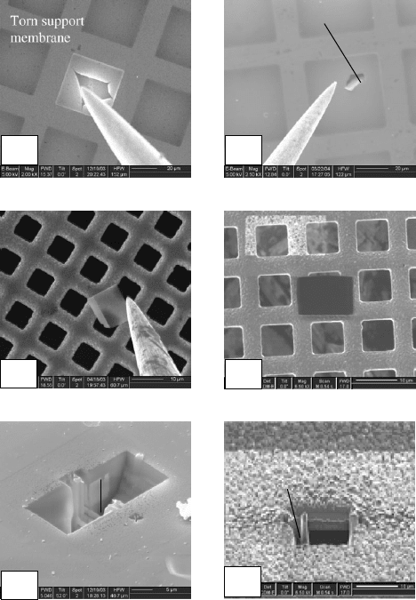
Figure 8.4 SE images of (a) a carbon suppo rt membr ane punctured by the
tip of the needle, (b) a lamella sat on a torn membr ane, (c) a Cu grid without
a support membrane onto which a TEM lamella has been placed and (d) the
same lamella after being pushed over a hole, (e) a lamella that has moved
against the sidewall of an FIB cut, and (f) a slice with a Pt strap that has
been used to ‘‘weld’’ the different layers.
Preparation for physico-chemical analysis 225
The lift-out step may also fail if the lamella jumps (due to electrostatics)
away from, or moves against, the sidewalls of the FIB cuts (Figure 8.4 (e)).
As the lamella is symmetrical in shape it can readily be distinguished from
any dirt or debris and thus, if it does jump away, it is possible, with patience,
to find it and to lift it up. If the lamella moves against the side of the cuts it
becomes difficult to see it with the optical microscope and to get it to attach
to the needle. Repeatedly swinging the needle back and forth against the side
of the FIB cut may knock and move the lamella such that it can then be lifted
out. Unfortunately, when doing this the tip of the glass needle may shatter
showering the FIB cuts and lamella in glass fragments.
Samples containing cracks or numerous layers that are poorly adhered can
also be difficult to lift out as these may fracture or the layers delaminate as
the needle tip is being pushed against them. Huang et al.[45] prevented the
fracturing of lamellae containing cracks by leaving a supporting frame
around the lamellae. For samples with poor adhesion between the layers, a Pt
strap may be deposited onto the face of the lamella (by tilting the sample to
45
) to ‘‘weld’’ the different layers together (Figure 8.4 (f)) before it is thinned
to electron transparency.
The lift-out step has also been performed in the chamber of FIB/SEM
systems using SE imaging [ 53]. This enables higher magnifications to be used
than is possible optically giving more control over positioning the needle
relative to the lamella and making it easier for new users to learn. In this
approach it was found that the highest yield occurred if a tungsten needle
with a radius of curvature of about 1 m m and an accelerating potential of
5 kV was used. Unfortunately, even though higher magnifications are pos-
sible the success yield of this approach (70%) is comparable to that of the
ex-situ lift-out method. This, when coupled with the fact that the FIB system
is being used for this step, means there is limited value in using this approach
relative to the ex-situ method or the in-situ slice method which is discussed in
the next section.
8.2.3 The in-situ slice technique
This technique can be viewed as a hybrid of the ex-situ lift-out and H-bar
techniques. It was first reported by Ohnishi et al.[29] but for many reasons
(such as patent issues and availability of suitable in-situ micromanipulators)
it has taken many years to become accepted within the FIB community and it
is only recently (circa 2005) that it has become the main FIB based technique
being used. The chief reason why this method has superseded the ex-situ lift-
out technique is because its success yield can be close to 100%. This high
Focused ion beam systems226
success yield is because Pt ‘‘welding’’ is used to fix a slice of the sample onto
the needle’s tip as against relying on electrostatic forces.
The in-situ micromanipulator is an integral part of this technique. These
have been mounted in the gas injector ports, on the stage, or on the sidewalls
of the chamber (Figure 8.5(a)). An advantage of mounting the micro-
manipulator independently of the stage is that the sample can be moved to
different locations while the tip of the needle remains fixed on the electro-optic
axis. In addition to manipulating TEM lamellae in-situ micromanipulators
(a)
(e) (f)
(b)
Base and side cuts
(c)
Needle Pt welded to a
slice
(d)
Slot grid
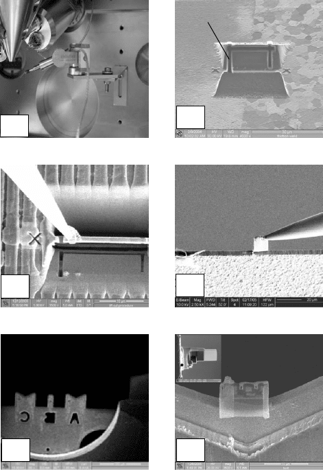
Figure 8.5 (a) Image of in-s itu micromanipulator mounted on the stage,
(b) SE image of a 500 nm thick slice that has had its base and sidewalls cut
through, (c) SE image of a needle ‘‘welded’’ to a slice, (d) SE image of a slice
being attached to a TEM slot grid, (e) SE image of a TEM grid with both
tabs and V-slots, and (f) SE images of thinned lamellae mounted on a
V-shape groove and a tab (insert) on a TEM grid.
Preparation for physico-chemical analysis 227