Zhang K., Li D. Electromagnetic Theory for Microwaves and Optoelectronics
Подождите немного. Документ загружается.


3.3 Transmission-Lines Charts 131
The contours of constant r and constant x are given by the following equa-
tions:
µ
u −
r
1 + r
2
+ v
2
=
µ
1
1 + r
2
, (u − 1)
2
+
µ
v −
1
x
2
=
µ
1
x
2
. (3.64)
Equation (3.64) shows that the loci of constant resistance r plotted on the
complex Γ plane are circles with centers on the real axis at u = r/(1+r), v =
0 and with radii 1/(1 + r), and the curves of constant reactance x are also
circles with centers at u = 1, v = 1/x and with radii 1/x. The circles
of constant r are common tangential to the line u = 1 and the circles of
constant x are common tangential to the line v = 0. They are two circle
families normal to each other with the common tangential point u = 1, v = 0.
The lines of constant x are arcs inside the unit circle on the Γ plane, for |Γ |
must be less then unity. See Fig. 3.9(a).
The circle of x = 0 is a horizontal straight line, v = 0, i.e., a circle with
its radius tending to infinity, which is the pure resistance line. The upper
half plane corresponds to inductance, x > 0, whereas the lower half plane
corresponds to capacitance, x < 0.
The circle of x → ±∞ is a circle with its center at u = 1, v = 0, and its
radius tending to zero, which reduces to the point u = 1, v = 0.
The locus of r = 0 is the circle |Γ | = 1, which is known as the pure
reactance circle.
The point of r = 0, x = 0 is located at u = −1, v = 0, where Γ = e
jπ
=
−1, which is the short-circuit point.
The locus of r → ∞ is also a circle with its center at u = 1, v = 0, and
its radius tending to zero, which reduces to the point u = 1, v = 0, where
r → ∞, x → ±∞ and Γ = e
jπ
= 1, which is known as the open-circuit point.
The locus of r = 1 is the circle with its center at u = 1/2, v = 0, and a
radius of 1/2, which is the pure resistance line.
At the origin of the Γ plane, r = 1, x = 0, and Γ = 0, which represents
the matching point, i.e., z = 1 or Z = Z
C
.
On the negative real axis, x = 0, r < 1, i.e., R < Z
C
, the angle of Γ is π;
the phase of the reflected wave is opposite to the phase of the incident wave,
which corresponds to the voltage standing-wave minimum. On the positive
real axis, x = 0, r > 1, i.e., R > Z
C
, the angle of Γ is 0, which corresp onds
to the voltage standing-wave maximum.
The loci of constant r and constant x on the Γ plane is shown in
Fig. 3.9(a).
In the Smith chart, the loci of constant |Γ | are concentric circles with the
center at the origin, which are also constant VSWR (or ρ) circles. The value
of r at the intersection point of the constant VSWR circle and the positive
real axis is just the value of VSWR.
The loci of constant φ are radial straight lines starting from the origin.
At the open-circuit point, u = 1, v = 0, φ = 0. At the short-circuit point,
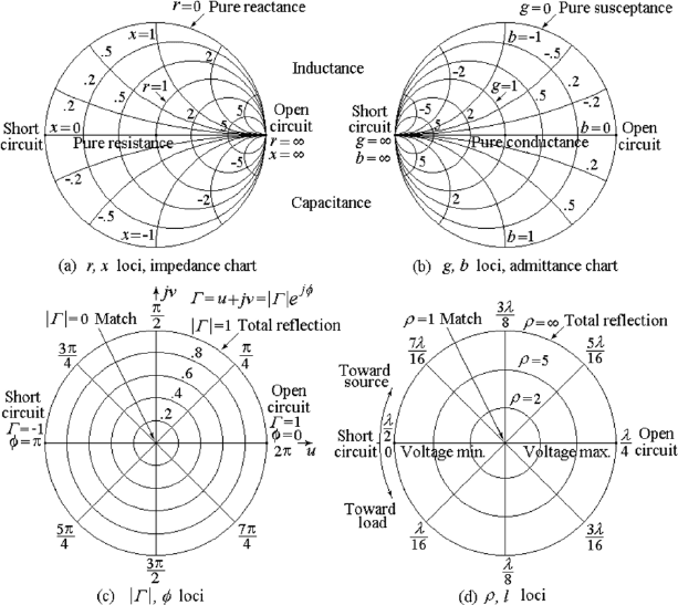
132 3. Transmission-Line and Network Theory for Electromagnetic Waves
Figure 3.9: The Smith chart.
u = −1, v = 0, φ = ±180
◦
. Phase φ increases in the counter-clockwise
direction.
The loci of constant |Γ | and constant φ, i.e., the polar coordinates of the
complex variable Γ are shown in Fig. 3.9(c).
For convenience, a scale giving the angular rotation 2βl = 4πl/λ in
terms of wavelength λ is attached along the circumference of the chart; see
Fig. 3.9(d). Note that moving away from the load toward the generator cor-
responds to going around the chart in a clockwise direction. A complete
revolution around the chart is made in going a distance λ/2 along the trans-
mission line; the λ here is the guided-wave wavelength in the transmission
system and is different from the free-space wavelength.
(2) The Smith Admittance Chart
The Smith admittance chart is a plot of the complex function of the normal-
ized admittance y = g + jb on the Γ plane in polar coordinates. The relation
between z and y is the inversion transformation, and we can see from (3.46)
3.3 Transmission-Lines Charts 133
Figure 3.10: The Schimdt Chart (a) and the Carter chart (b).
that the relation between y and −Γ is the same as the relation between z and
Γ . This means that the reflection coefficient Γ on the admittance chart is the
negative of that on the impedance chart; in other words, the difference be-
tween φ, the angle of Γ on the admittance chart, and that on the impedance
chart is 180
◦
. The point where g = 0 and b = 0 is the open-circuit point,
where Γ = 1, and the point where g → ±∞ and b → ±∞ is the short-circuit
point, where Γ = −1. So we do not need to plot a new chart for the ad-
mittance, we need only to rotate the loci of r and x for 180
◦
on the fixed Γ
plane, then we have the Smith admittance chart. See Fig. 3.9(b).
A Smith chart with more divisions suitable for practical calculation is
given in an attached page.
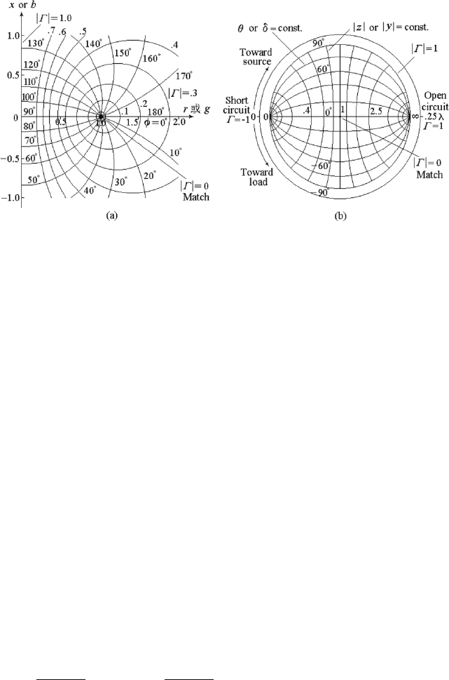
3.3.2 The Schimdt Chart
The Schimdt chart is the loci of |Γ | and angle φ in the plane z = x + jy
or y = g + jb. The effective region for a passive transmission line is the
right-hand half plane, i.e., r > 0 in the z plane or g > 0 in the y plane.
The contours of constant |Γ | and constant φ are given by the following
equations:
µ
r −
1 + |Γ |
2
1 − |Γ |
2
2
+ x
2
=
µ
2|Γ |
1 − |Γ |
2
2
, r
2
+ (x − cot φ)
2
= csc
2
φ. (3.65)
The loci of constant |Γ | and constant φ are also two circle families and are
normal to each other, see Fig. 3.10(a).

134 3. Transmission-Line and Network Theory for Electromagnetic Waves
3.3.3 The Carter Chart
The Carter chart is a plot of the normalized impedance in polar coordinates
z = |z|e
jθ
or normalized admittance y = |y|e
jδ
on the Γ = |Γ |e
jφ
= u + jv
plane .
The contours of constant |z| and constant θ are given by the following
equations:
µ
u +
1 + |z|
2
1 − |z|
2
2
+ v
2
=
µ
2|z|
1 − |z|
2
2
, u
2
+ (v + cot θ)
2
= csc
2
θ. (3.66)
The loci of constant |z| and constant θ in the Carter chart are the same as
the loci of constant |Γ | and constant φ in the Schimdt chart, but the effective
region in the Carter chart is the interior of the unit circle, and the effective
region in the Schimdt chart is the right-hand half plane, see Fig. 3.10(b).
3.3.4 Basic Applications of the Smith Chart
Some examples of basic applications of the Smith chart are as follows:
1. to find the VSWR and the position of the voltage minimum from a
given impedance, and vice versa;
2. to find the reflection coefficient from a given impedance, and vice versa;
3. to transform impedance along the line;
4. to find the admittance from a given impedance, and vice versa;
5. to find the sum of the imp edance or admittance.
3.4 The Equivalent Transmission Line of Wave
Systems
The transmission-line theory is derived for the TEM wave system, but it
can be used to simulate any mode in an arbitrary guided-wave system. This
simulation is known as the equivalent transmission line of the guided-wave
system.
In field theory, the power flow in a guided-wave system is carried out by
the transverse component of the electric and magnetic fields. The power flow
along the longitudinal direction is given by
P =
Z
S
<
µ
1
2
E
T
× H
∗
T
· dS, (3.67)

3.4 The Equivalent Transmission Line of Wave Systems 135
where subscript T means transverse components. In circuit theory, the power
flow along the transmission line is given by
P = <
µ
1
2
UI
∗
. (3.68)
Hence E
T
can be simulated by U and H
T
can be simulated by I as follows:
E
T
(T , z) = E
T
(T )U(z), H
T
(T , z) = H
T
(T )I(z), (3.69)
where (T ) denotes the transverse coordinates (u
1
, u
2
).
The characteristic impedance of a guided-wave system is defined by the
ratio of the following two integrals:
Z
C
=
R
l
1
E · dl
R
l
2
H · dl
, (3.70)
where l
1
denotes an integral path along the electric field line between two
conducting surfaces, and l
2
denotes an integral path along the magnetic field
line, i.e., perpendicular to the surface current on a conductor surface. The
characteristic impedance of a guided-wave system is usually not unique except
for a TEM wave system.
The characteristic impedance of a guided-wave system can be simulated
by the characteristic impedance of the equivalent transmission line Z
C
. The
normalized impedance at any cross section of the guided-wave system is given
by:
z =
Z
Z
C
, Z =
U
I
. (3.71)
The normalized voltage and the normalized current can then be defined as
follows:
u =
U
√
Z
C
, i = I
p
Z
C
. (3.72)
Then we have
u
i
= z, and <
µ
1
2
ui
∗
= P. (3.73)
Then E
T
and H
T
in (3.74) become
E
T
(T , z) = e
T
(T )u(z), H
T
(T , z) = h
T
(T )i(z). (3.74)
It can be seen from (3.67) and (3.73) that the transverse vector functions
e
T
(T ) and h
T
(T ) must satisfy the following equation:
Z
S
[e
T
(T ) × h
T
(T )] · dS = 1. (3.75)
Notice that the normalized impedance is a dimensionless quantity, the
normalized characteristic impedance is unity, and both the dimensions of the
136 3. Transmission-Line and Network Theory for Electromagnetic Waves
normalized voltage and normalized current are (V A)
1/2
, i.e., W
1/2
. The
meaning of them is no longer the original meaning of voltage and current.
The normalized impedance or normalized admittance can be determined
by the VSWR and the position of the voltage minimum or the reflection
coefficient in the guided-wave system by using (3.36), (3.37) and (3.46).
3.5 Introduction to Network Theory
The impedance concepts introduced in the last section reminds us of using
networks to simulate the reflection and transmission in guided-wave systems.
The network theory developed in the investigation of the electric circuit has
been successfully applied to the problems in electromagnetic fields and waves.
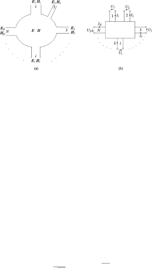
Consider a closed region with time-varying electromagnetic fields in it and
with several terminals connected to the outside of it. The enclosed surface not
including the terminals is a perfect conductor or short-circuit surface. The
terminals are lossless waveguides with only one propagation mode, namely
the dominant mode in each waveguide, and any other higher-order modes are
cutoff modes.
On the terminal waveguides, reference planes are placed far enough from
the junctions so that all cutoff modes have decayed out. In network simulation
of field problems, only tangential electric and magnetic field components of
the dominant mode on the reference plane are to be considered. We may
construct an equivalent circuit or network with several ports or terminal
pairs, called a multi-port network or simply a multi-port to simulate the field
structure and to determine the relations among the fields at various reference
planes. [84]. The tangential components of the electric and magnetic fields at
the reference planes may be simulated by means of the voltages and currents
at the corresponding ports of the network. See Fig. 3.11.
3.5.1 Network Matrix and Parameters
of a Linear Multi-Port Network
Maxwell’s equations are linear, so we may simulate the field structure by
means of a linear multi-port. The relations among voltages and currents at
various ports of a linear network must be a set of linear equations, and can
be expressed in the form of matrices, which are known as network matrices.
The elements of the network matrices are called network parameters.
(1) The Impedance Matrix
For an N-port network, the voltage at each port U
1
, U
2
, ···U
i
, ···U
N
may be
expressed in terms of the currents at all ports I
1
, I
2
, ···I
i
, ···I
N
by means
3.5 Introduction to Network Theory 137
Figure 3.11: Multi-port network.
of the following linear equations:
U
i
=
N
X
j=1
Z
ij
I
j
, i = 1, 2, ···N, j = 1, 2, ···N. (3.76)
The matrix form of the above linear equations is given by
U
1
U
2
···
···
U
i
···
···
U
N
=
Z
11
Z
12
··· Z
1j
··· Z
1N
Z
21
Z
22
··· Z
2j
··· Z
2N
··· ··· ··· ··· ··· ···
··· ··· ··· ··· ··· ···
Z
i1
Z
i2
··· Z
ij
··· Z
iN
··· ··· ··· ··· ··· ···
··· ··· ··· ··· ··· ···
Z
N1
Z
N2
··· Z
Nj
··· Z
NN
I
1
I
2
···
···
I
i
···
···
I
N
. (3.77)
The abbreviated form of the above expression is
(U) = (Z)(I), (3.78)
where (U) and (I) denote the voltage matrix and the current matrix, respec-
tively, which are column matrices, and (Z) is a square matrix, which denotes
the impedance matrix or Z matrix. Z
ii
denotes the self impedance of the
ith port, which is the ratio of U
i
to I
i
when the other ports are open. Z
ij
denotes the mutual impedance of the ith and the jth port, which is the ratio
of U
i
to I
j
when the ports other then the jth port are open.
The normalized voltage and the normalized current of the ith port can
be defined by (3.72) as follows:
u
i
=
U
i
√
Z
Ci
, i
i
= I
i
p
Z
Ci
, (3.79)

138 3. Transmission-Line and Network Theory for Electromagnetic Waves
where Z
Ci
denotes the characteristic impedance of the equivalent transmis-
sion line of the waveguide connected to the ith port. Then the normalized
self impedance and the normalized mutual impedance become
z
ii
=
Z
ii
Z
Ci
, z
ij
=
Z
ij
p
Z
Ci
Z
Cj
, (3.80)
respectively. The normalized imp edance matrix equation can then be written
as
u
1
u
2
···
···
u
i
···
···
u
N
=
z
11
z
12
··· z
1j
··· z
1N
z
21
z
22
··· z
2j
··· z
2N
··· ··· ··· ··· ··· ···
··· ··· ··· ··· ··· ···
z
i1
z
i2
··· z
ij
··· z
iN
··· ··· ··· ··· ··· ···
··· ··· ··· ··· ··· ···
z
N1
z
N2
··· z
Nj
··· z
NN
i
1
i
2
···
···
i
i
···
···
i
N
, (3.81)
or
(u) = (z)(i), (3.82)
where (z) denotes the normalized impedance matrix or z matrix.
The impedance matrix is suitable for the calculation of a series-connected
network, which consists of several networks with series connection of corre-
sponding ports. The impedance matrix of a series-connected network is equal
to the sum of the impedance matrices of all the n elementary networks:
(z) =
n
X
k=1
(z)
k
. (3.83)
(2) The Admittance Matrix
The currents at each port may also be expressed in terms of the voltages
at all ports, and we can have the normalized admittance matrix equation as
follows:
i
1
i
2
···
···
i
i
···
···
i
N
=
y
11
y
12
··· y
1j
··· y
1N
y
21
y
22
··· y
2j
··· y
2N
··· ··· ··· ··· ··· ···
··· ··· ··· ··· ··· ···
y
i1
y
i2
··· y
ij
··· y
iN
··· ··· ··· ··· ··· ···
··· ··· ··· ··· ··· ···
y
N1
y
N2
··· y
Nj
··· y
NN
u
1
u
2
···
···
u
i
···
···
u
N
, (3.84)
or
(i) = (y)(u), (3.85)

3.5 Introduction to Network Theory 139
where (y) denotes the normalized admittance matrix or y matrix, and
y
ii
=
Y
ii
Y
Ci
, y
ij
=
Y
ij
p
Y
Ci
Y
Cj
, (3.86)
where Y
ii
denotes the self admittance of the ith port, which is the ratio of I
i
to U
i
when the other ports are short. Y
ij
denotes the mutual admittance of
the ith and the ith port, which is the ratio of I
i
to U
j
when all ports except
the jth port are short.
The admittance matrix is suitable for the calculation of a parallel-
connected network, which consists of several networks with parallel connec-
tion of corresponding ports. The admittance matrix of a parallel-connected
network is equal to the sum of the admittance matrices of all the n elementary
networks.
(y) =
n
X
k=1
(y)
k
. (3.87)
Multiplying equation (3.85) by (y)
−1
, yields
(y)
−1
(i) = (y)
−1
(y)(u) = (u).
Comparing this equation and (3.82), we have
(z) = (y)
−1
, (y) = (z)
−1
, or (z)(y) = (I), (3.88)
where (I) is the unit matrix. So the matrices (z) and (y) are inverse matrices
to each other.
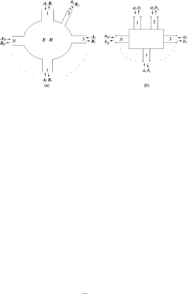
(3) The Scattering Matrix
In the transmission-line theory, the state of the wave on the line can be
described by the impedance, admittance and reflection coefficient. The
impedance or admittance is the ratio of the complex amplitude of the voltage
to that of the current or vice versa at a specified point on the line, whereas
the reflection coefficient is the ratio of the complex amplitude of the reflected
wave to that of the incident wave. Similarly, the state of the multi-port net-
work can also be formulated by the relations among the complex amplitudes
of the inward and the outward waves in each port. The inward wave is the
incident wave coming from the generator toward the network through the
port, and the outward wave is the wave coming outward from the network
through the port, including the reflected wave in the port itself and the trans-
missive wave from the other ports through the network. The formulation of
this relationship is known as the scattering matrix.
Suppose the complex amplitudes of the normalized voltages of the inward
and outward waves at port i are denoted by a
i
and b
i
, respectively, i = 1 to N.
See Fig. 3.12.
140 3. Transmission-Line and Network Theory for Electromagnetic Waves
Figure 3.12: Inward and outward waves at the ports of a multi-port network.
The normalized voltage of the outward wave b
i
may be expressed in terms
of the normalized voltage of the inward wave a
i
by means of the following
linear equations:
b
1
b
2
···
···
b
i
···
···
b
N
=
S
11
S
12
··· S
1j
··· S
1N
S
21
S
22
··· S
2j
··· S
2N
··· ··· ··· ··· ··· ···
··· ··· ··· ··· ··· ···
S
i1
S
i2
··· S
ij
··· S
iN
··· ··· ··· ··· ··· ···
··· ··· ··· ··· ··· ···
S
N1
S
N2
··· S
Nj
··· S
NN
a
1
a
2
···
···
a
i
···
···
a
N
. (3.89)
The abbreviated form of the above expression is
(b) = (S)(a), (3.90)
where (a) and (b) denote the inward-wave matrix and the outward-wave ma-
trix, respectively, which are column matrices, and (S) is a square matrix,
which denotes the scattering matrix or S matrix. S
ii
and S
ij
are the scat-
tering parameters of the network. The physical meaning of S
ii
is the ratio of
the amplitude of the outward wave b
i
to the amplitude of the inward wave
a
i
when a matched generator is connected at the port i and the other ports
are matched, which is the matched reflection coefficient of the ith port of the
network:
S
ii
=
b
i
a
i
¯
¯
¯
¯
matched ports
. (3.91)
The physical meaning of S
ij
is the ratio of the amplitude of the outward
wave b
i
to the amplitude of the inward wave a
j
when a matched generator is