Zhang K., Li D. Electromagnetic Theory for Microwaves and Optoelectronics
Подождите немного. Документ загружается.


3.7 Impedance Transducers 161
Note that in the first expression, the admittance is normalized by Z
C1
, i.e.,
y = Y Z
C1
, whereas in the second expression, the admittance is normalized
by Z
C1
, i.e., y = Y Z
C2
, so the above two expressions become the following
expression:
(a) =
r
Z
C2
Z
C1
0
Y
√
Z
C1
Z
C2
r
Z
C1
Z
C2
. (3.157)
3.7 Impedance Transducers
The characteristics of the reflection and transmission of electromagnetic
waves at the surface of multi-layer dielectric coating are introduced in Sec-
tion 2.6. A multi-layer dielectric coating is equivalent to an imp edance trans-
ducer consists of multi-section transmission lines or waveguides with different
characteristic impedances, and can be investigated by means of network the-
ory.
This section may be seen as an example of the application of transmission
line simulation and network simulation in electromagnetic wave problems.
We begin with the single-layer coating or λ/4 impedance transducer, given
in section 2.6.1.
3.7.1 The Network Approach to the λ/4 Anti-Reflection
Coating and the λ/4 Impedance Transducer
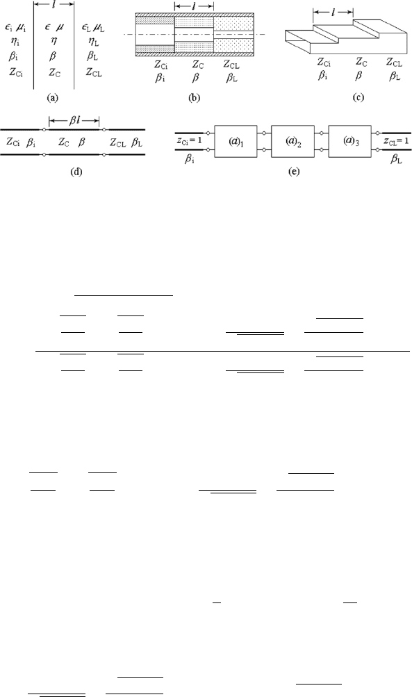
A single layer coating between two media with different wave impedances, the
single-section waveguide, and the coaxial-line transducer are equivalent to a
segment of transmission line with characteristic impedance Z
C
, connected
between two transmission lines with different characteristic impedance Z
Ci
and Z
CL
, which forms a single-section impedance transducer. See Fig. 3.21.
The normalized transfer matrix of this kind of structure is given from (3.154)
as
(a) = (a)
1
(a)
2
(a)
3
=
r
Z
CL
Z
Ci
cos βl j
Z
C
p
Z
Ci
Z
CL
sin βl
j
p
Z
Ci
Z
CL
Z
C
sin βl
r
Z
Ci
Z
CL
cos βl
, (3.158)
where β denotes the phase coefficient of the intermediate medium.
The insertion reflection coefficient of the network is given by (3.132). By
using the relation between matrices (S) and (a) given in Table 3.2, we have
162 3. Transmission-Line and Network Theory for Electromagnetic Waves
Figure 3.21: Single dielectric layer and single-section impedance transducer.
Γ
1
= S
11
=
(a + b) − (c + d)
a + b + c + d
=
µ
r
Z
C2
Z
C1
−
r
Z
C1
Z
C2
cos βl + j
µ
Z
C
√
Z
C1
Z
C2
−
√
Z
C1
Z
C2
Z
C
sin βl
µ
r
Z
C2
Z
C1
+
r
Z
C1
Z
C2
cos βl + j
µ
Z
C
√
Z
C1
Z
C2
+
√
Z
C1
Z
C2
Z
C
sin βl
.
(3.159)
For an anti-reflection coating or a impedance transducer, Γ
1
must b e zero,
i.e., the numerator of the above expression must be zero:
Ã
r
Z
CL
Z
Ci
−
r
Z
Ci
Z
CL
!
cos βl + j
µ
Z
C
√
Z
Ci
Z
CL
−
√
Z
Ci
Z
CL
Z
C
sin βl = 0.
The real and imaginary parts must be zero separately. The first factor of the
real part cannot be zero, for Z
Ci
6= Z
CL
. So that the condition for the real
part to be zero is
cos βl = 0, i.e., β
0
l = (2n + 1)
π
2
, or l = (2n + 1)
λ
0
4
, (3.160)
where λ
0
is the center frequency of the transducer. Under this condition,
sin βl = 1, the condition of the imaginary part being zero becomes
Z
C
√
Z
Ci
Z
CL
−
√
Z
Ci
Z
CL
Z
C
= 0, i.e., Z
C
=
p
Z
Ci
Z
CL
. (3.161)
These are just the conditions obtained before, (2.258) and (2.260).
3.7 Impedance Transducers 163
0.0 .2 .4 .6 .8 1.0 1.2 1.4 1.6 1.8 2.0
1.0
1.1
1.2
1.3
1.4
1.5
1.6
1.7
1.8
1.9
2.0
n = 0
N = 1
U
(VSWR)
0.0 .2 .4 .6 .8 1.0 1.2 1.4 1.6 1.8 2.0
1.0
1.1
1.2
1.3
1.4
1.5
1.6
1.7
1.8
1.9
2.0
2
1
U
(VSWR)
n = 0
N = 1
(a)
(b)
2
5.1
C1C2
ZZ
3
3
C1C2
ZZ
0
OO
0
OO
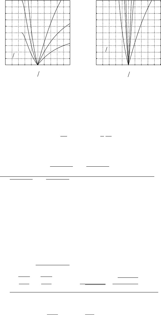
Figure 3.22: Frequency response of the single segment λ/4 impedance trans-
ducer.
For the wave with an arbitrary wavelength λ,
βl =
2π
λ
l = (2n + 1)
π
2
λ
0
λ
.
Substituting it and (3.161) into (3.159), we have the frequency response of
the transducer:
Γ
1
=
³
p
Z
CL
/Z
Ci
−
p
Z
Ci
/Z
CL
´
³
p
Z
CL
/Z
Ci
+
p
Z
Ci
/Z
CL
´
+ j2 tan [(2n + 1)(π/2)(λ
0
/λ)]
. (3.162)
The VSWR of the input port can then be calculated by means of (3.133).
The results of the calculation are given in Fig. 3.22. It can be seen from figure
(a) that the larger the impedance ratio Z
Ci
/Z
CL
the narrower the bandwidth,
and from figure (b) that the longer the transducer, i.e., the larger the number
n in (3.160), the narrower the bandwidth.
The other parameter for describing the characteristics of the transducer
is the insertion attenuation, which is the reflection attenuation only, because
the network is lossless. The insertion attenuation is given in (3.134):
L= |T
11
|
2
=
¯
¯
¯
¯
a + b + c + d
2
¯
¯
¯
¯
2
=
µ
r
Z
C2
Z
C1
+
r
Z
C1
Z
C2
2
cos
2
βl+
µ
Z
C
√
Z
C1
Z
C2
+
√
Z
C1
Z
C2
Z
C
2
sin
2
βl
4
. (3.163)
Let
R =
Z
CL
Z
Ci
, P =
Z
C
Z
Ci
, θ = βl,

164 3. Transmission-Line and Network Theory for Electromagnetic Waves
which yields
L = |T
11
|
2
= A
0
+ A
1
cos
2
θ, (3.164)
where
A
0
=
1
4
Ã
P
√
R
+
√
R
P
!
2
, (3.165)
A
1
=
1
4
µ
√
R −
1
√
R
2
−
Ã
P
√
R
−
√
R
P
!
2
. (3.166)
The condition of matching is
L = |T
11
|
2
= 1, or A
1
cos
2
θ
0
+ A
0
− 1 = 0. (3.167)
The root of the above equation is
cos
2
θ
0
=
1 − A
0
A
1
.
The condition for a real root of cos θ is A
0
< 1. But it can be seen in (3.165)
that A
0
is always larger or equal to 1. Hence the only root is
P =
√
R, i.e., Z
C
=
p
Z
Ci
Z
CL
, and cos θ
0
= 1. (3.168)
Under this condition,
A
0
= 1, A
1
=
1
4
µ
√
R −
1
√
R
2
,
the insertion attenuation becomes
L = |T
11
|
2
= 1 +
1
4
µ
√
R −
1
√
R
2
cos
2
θ. (3.169)
This is also a frequency response expression of the single-section λ/4
impedance transducer.
For a lossless and source-free network, the relation between |T
11
|, |S
11
|,
or |Γ
1
| and VSWR is given by (3.140):
L = L
R
= |T
11
|
2
=
1
1 − |S
11
|
2
=
1
1 − |Γ
1
|
2
=
(ρ + 1)
2
4ρ
. (3.170)
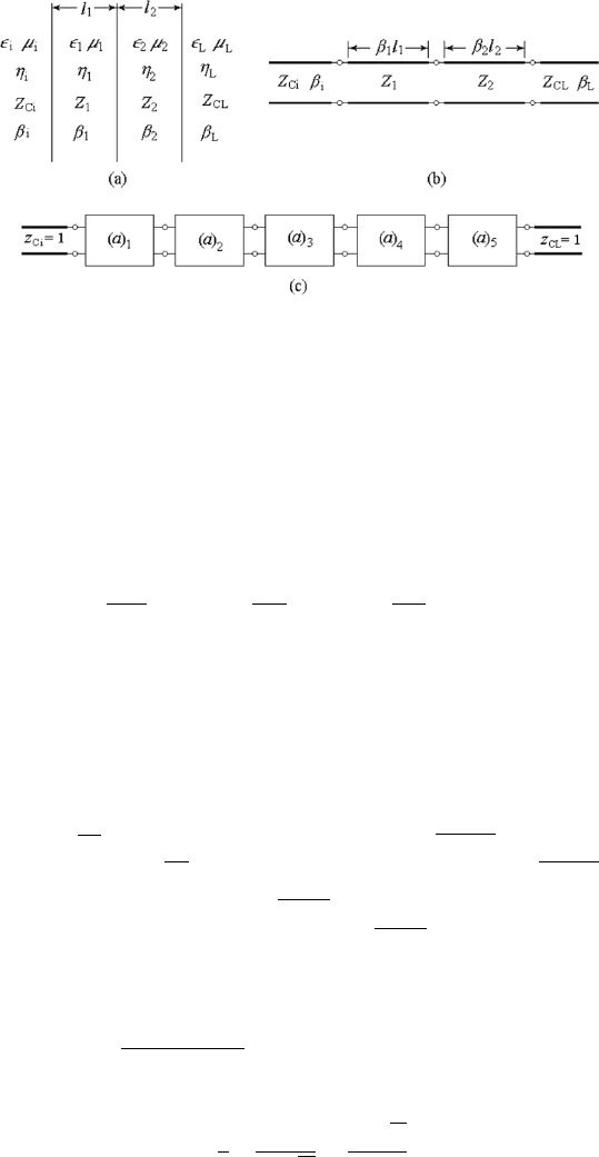
3.7.2 The Double Dielectric Layer,
Double-Section Impedance Transducers
The bandwidth of a single-section transducer is narrow. To broaden the
bandwidth, we may increase the sections of the transducer. We start with
3.7 Impedance Transducers 165
Figure 3.23: Double dielectric layer and double section impedance transducer.
the double-section transducer or double matching layer shown in Fig 3.23(a),
(b).
Suppose the characteristic impedance of the input and output waveguides
are Z
Ci
and Z
CL
, respectively, the characteristic impedance of the two inter-
mediate sections are Z
1
and Z
2
, respectively. The length of each intermediate
section is l. Then we have
R =
Z
CL
Z
Ci
, P
1
=
Z
1
Z
Ci
, P
2
=
Z
2
Z
Ci
, θ = βl,
The double-section transducer consists of five cascade-connected two-ports
including two segments of transmission line and three connectors, as shown
in Fig. 3.23(c). The network matrix is given by the product of matrices of
the five elementary networks:
(a) =
·
a b
c d
¸
= (a)
1
(a)
2
(a)
3
(a)
4
(a)
5
=
·
√
P
1
0
0 1/
√
P
1
¸·
cos θ j sin θ
j sin θ cos θ
¸·
p
P
2
/P
1
0
0
p
P
1
/P
2
¸
×
·
cos θ j sin θ
j sin θ cos θ
¸·
p
R/P
2
0
0
p
P
2
/R
¸
. (3.171)
The insertion attenuation of the network is given by
L = |T
11
|
2
=
¯
¯
¯
¯
a + b + c + d
2
¯
¯
¯
¯
2
= A
0
+ A
1
cos
2
θ + A
2
cos
4
θ, (3.172)
where
A
0
=
1
4
Ã
P
2
P
1
√
R
+
P
1
√
R
P
2
!
2
, (3.173)

166 3. Transmission-Line and Network Theory for Electromagnetic Waves
A
1
=
1
4
Ã
P
2
√
R
+
√
R
P
1
!
2
µ
1 +
P
1
P
2
2
− 2
Ã
1
√
R
+
√
R +
P
2
P
1
√
R
+
P
1
√
R
P
2
!
×
Ã
P
2
P
1
√
R
+
P
1
√
R
P
2
!#
, (3.174)
A
2
=
1
4
Ã
1
√
R
+
√
R +
P
2
P
1
√
R
+
P
1
√
R
P
2
!
2
−
Ã
P
2
√
R
+
√
R
P
1
!
2
µ
1+
P
1
P
2
2
.
(3.175)
The condition of matching is L = |T
11
|
2
= 1, which yields
A
2
cos
4
θ
0
+ A
1
cos
2
θ
0
+ A
0
− 1 = 0. (3.176)
This is a quadratic equation of cos
2
θ, and has two independent roots. Hence
the double-section transducer must have two matching points, and the band-
width is broader then that of the single-section one.
3.7.3 The Design of a Multiple Dielectric Layer
or Multi-Section Impedance Transducer
There are two branches in network theory, network analysis and network
synthesis. The purpose of network analysis is to find the characteristics of a
given network and the purpose of network synthesis is to design a network
to meet the required characteristics. The result of synthesis is mostly not
unique. The design of a multiple dielectric layer or multi-section impedance
transducer is an example of the basic principle of network synthesis.
(1) The Network Equation of a Multi-Section
Impedance Transducer
In the preceding two sections, we noted that the single-section transducer
consists of 3 cascade-connected two-ports, and the double-section transducer
consists of 5 cascade-connected two-ports. Therefore, we may predict that the
N-section transducer must consists of 2N + 1 cascade-connected two-ports.
The transfer matrix of the N-section transducer are obtained via
(a) =
·
a b
c d
¸
= (a)
1
(a)
2
(a)
3
······(a)
2N
(a)
2N+1
. (3.177)
We do not want to develop the expression of the insertion attenuation
of a multi-section transducer in detail, but we may infer the form of it by
investigating those of the single- and double-section transducers (3.164) and
(3.172).

3.7 Impedance Transducers 167
For a single-section transducer, N = 1,
L =
¯
¯
¯
¯
a + b + c + d
2
¯
¯
¯
¯
2
= A
0
+ A
1
cos
2
θ,
and for a two-section transducer, N = 2,
L =
¯
¯
¯
¯
a + b + c + d
2
¯
¯
¯
¯
2
= A
0
+ A
1
cos
2
θ + A
2
cos
4
θ.
Then we may infer that, for a three-section transducer, N = 3,
L =
¯
¯
¯
¯
a + b + c + d
2
¯
¯
¯
¯
2
= A
0
+ A
1
cos
2
θ + A
2
cos
4
θ + A
3
cos
6
θ. (3.178)
And finally for an N-section transducer,
L=
¯
¯
¯
¯
a+b+c+d
2
¯
¯
¯
¯
2
=A
0
+ A
1
cos
2
θ + A
2
cos
4
θ + ···+ A
N
cos
2N
θ =
N
X
n=0
A
n
cos
2n
θ,
(3.179)
where A
n
are determined by comparing the coefficients of the equation. Co-
efficients A
n
are the functions of the following parameters:
R =
Z
CL
Z
Ci
, P
n
=
Z
n
Z
Ci
, (3.180)
where Z
Ci
and Z
CL
denote the characteristic impedance of the input and out-
put waveguides, Z
n
denotes the characteristic impedance of the nth section
of intermediate waveguide.
The matching condition of the N-section impedance transducer must be
N
X
n=0
A
n
(cos
2
θ)
n
− 1 = 0. (3.181)
This is an equation for the nth order of cos
2
θ with N roots. Therefore, the
transducer must have N matching points. The larger the number of sections,
N, the broader the bandwidth.
For the design of a multi-section transducer, giving the bandwidth and
the maximum VSWR, the characteristic impedance of each section Z
n
can
be found by solving (3.179). The solution is not unique when the number
of sections is larger than 1. So, for a multi-section transducer, there are a
number of designs. The most popular design is the Chebyshev polynomial
design and the binomial design. The former gives a equal ripple response and
the latter gives a flatness response.

168 3. Transmission-Line and Network Theory for Electromagnetic Waves
(2) Chebyshev Polynomials
Chebyshev (or Tchebyscheff) functions or polynomials are the two linearly
independent solutions of the differential equation [44]
¡
1 − x
2
¢
d
2
y
dx
2
− x
dy
dx
+ n
2
x = 0. (3.182)
The Chebyshev functions of the first kind and the second kind of the nth
order, T
n
(x) and U
n
(x), are given as
T
n
(x) = cos (n arccos x) =
1
2
h³
x+ j
p
1−x
2
´
n
+
³
x− j
p
1−x
2
´
n
i
. (3.183)
U
n
(x) = sin (n arccos x) =
1
2j
h³
x+ j
p
1−x
2
´
n
−
³
x− j
p
1−x
2
´
n
i
. (3.184)
Suppose that
cos u = x, i.e., arccos x = u.
We have
T
n
(x) = T
n
(cos u) = cos nu, (3.185)
U
n
(x) = U
n
(cos u) = sin nu. (3.186)
By expanding the functions cos nu and sin nu into polynomials, we may ex-
press the Chebyshev functions as the following polynomials:
T
n
(x) = (−1)
n
√
1 − x
2
1 · 3 · 5 ···(2n −1)
d
n
d x
n
¡
1 − x
2
¢
n−1/2
,
= x
n
− C
2
n
x
n−2
¡
1 − x
2
¢
+ C
4
n
x
n−4
¡
1 − x
2
¢
2
− ···, (3.187)
U
n
(x) = (−1)
n−1
n
1 · 3 · 5 ···(2n −1)
d
n−1
d x
n−1
¡
1 − x
2
¢
n−1/2
.
=
p
1−x
2
h
C
1
n
x
n−1
−C
3
n
x
n−3
¡
1−x
2
¢
+C
5
n
x
n−5
¡
1−x
2
¢
2
−···
i
, (3.188)
where
C
k
n
=
n!
(n − k)!k!
, k = 1, 2, 3, ···
is the combination without repetition. The recursion formulas of the Cheby-
shev polynomials are
T
n+1
(x)=2xT
n
(x)−T
n−1
(x), U
n+1
(x)=2xU
n
(x)−U
n−1
(x). (3.189)
The useful functions in network synthesis are the Chebyshev functions of
the first kind. The following are Chebyshev polynomials of the first kind of
the lowest degrees:
T
0
(x) = 1, T
4
(x) = 8x
4
− 8x
2
+ 1,
T
1
(x) = x, T
5
(x) = 16x
5
− 20x
3
+ 5x,
T
2
(x) = 2x
2
− 1, T
6
(x) = 32x
6
− 48x
4
+ 18x
2
− 1,
T
3
(x) = 4x
3
− 3x, T
7
(x) = 64x
7
− 112x
5
+ 56x
3
− 7x,
3.7 Impedance Transducers 169
-2.0 -1.5 -1.0 -.5 0.0 .5 1.0 1.5 2.0
-2
-1
0
1
2
3
4
x
-2.0 -1.5 -1.0 -.5 0.0 .5 1.0 1.5 2.0
-2
-1
0
1
2
3
4
x
-2.0 -1.5 -1.0 -.5 0.0 .5 1.0 1.5 2.0
-2
-1
0
1
2
3
4
x
-2.0 -1.5 -1.0 -.5 0.0 .5 1.0 1.5 2.0
-2
-1
0
1
2
3
4
x
)(T
2
1
x
)(T
1
x
)(T
2
2
x
)(T
2
3
x
)(T
3
x
)(T
2
x
)(T
2
4
x
)(T
4
x
)(T
)(T
2
1
1
x
x
)(T
)(T
2
2
2
x
x
)(T
)(T
2
3
3
x
x
)(T
)(T
2
4
4
x
x
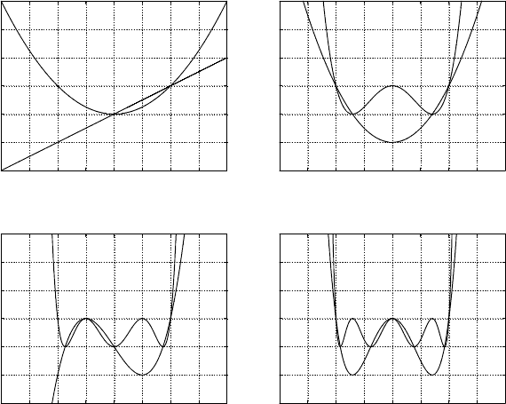
Figure 3.24: The Chebyshev polynomials T
n
(x) and T
2
n
(x).
The plots of the functions T
n
(x) and T
2
n
(x) of the lowest degrees are shown
in Figure 3.24.
From (3.187) and Fig. 3.24, it can b e seen that
1. T
n
(x) is an odd function when n is odd and is an even function when
n is even. Nevertheless, functions T
2
n
(x) are always even functions.
2. The value of T
n
(x) oscillates between −1 and +1 within the range of
|x| ≤ 1 and has n zeros.
3. When |x| > 1, the value of T
n
(x) tends to +∞ or −∞ with the rate of
x
n
.
These features meet the requirement of the equal ripple response of a two
port network and a transducer designed by means of Chebyshev approach
is the shortest one for satisfying the required bandwidth and the maximum
VSWR.

170 3. Transmission-Line and Network Theory for Electromagnetic Waves
(3) Principle of the Design of a Chebyshev Transducer
We choose the following function to fit the frequency response of the insertion
attenuation:
L = |T
11
|
2
= 1 + h
2
T
2
N
(x) = 1 + h
2
T
2
N
µ
cos θ
p
. (3.190)
The matching condition will be satisfied at points with T
2
N
(x) = 0, and the
band edges correspond to x = ±1, i.e.,
x =
cos θ
p
= ±1, θ = βl =
2π
λ
l.
The wavelengths of the band edges are
λ
max
=
2πl
arccos p
, x = +1, (3.191)
λ
min
=
2πl
π − arccos p
, x = −1. (3.192)
Let
q =
λ
max
λ
min
=
π − arccos p
arccos p
(3.193)
denoting the bandwidth ratio, which yields
p = cos
π
1 + q
. (3.194)
The insertion attenuation will be maximum at the points T
2
N
(x) = 1, i.e.,
L = |T
11
|
2
= 1 + h
2
.
According to the relation between the insertion attenuation and the VSWR
for lossless, source-free networks, (3.170),
1 + h
2
=
(ρ
max
+ 1)
2
4ρ
max
, h
2
=
(ρ
max
− 1)
2
4ρ
max
. (3.195)
Therefore, the parameter p is determined by the bandwidth ratio q and the
parameter h
2
is determined by the allowed maximum VSWR.
Let (3.179) be equal to (3.190). This yields
A
0
+A
1
cos
2
θ +A
2
cos
4
θ +A
3
cos
6
θ + ······A
N
cos
2N
θ = 1+ h
2
T
2
N
µ
cos θ
p
.
(3.196)
Both sides of the equation are polynomials of cos
2
θ of N th order. The unde-
termined A
0
to A
N
can be obtained by means of comparing coefficients. The