Zhang K., Li D. Electromagnetic Theory for Microwaves and Optoelectronics
Подождите немного. Документ загружается.


6.2 Symmetrical Planar Dielectric Waveguides 331
Region 2, x ≤ −h:
U
2
= Ce
τx
e
−jβz
, (6.81)
E
y 2
= jωµ
2
τCe
τx
e
−jβz
, (6.82)
H
x2
= −jβτ Ce
τx
e
−jβz
, (6.83)
H
z2
= −τ
2
Ce
τx
e
−jβz
; (6.84)
Region 3, x ≥ h:
U
3
= De
−τx
e
−jβz
, (6.85)
E
y 3
= −jωµ
2
τDe
−τx
e
−jβz
, (6.86)
H
x3
= jβτ De
−τx
e
−jβz
, (6.87)
H
z3
= −τ
2
De
−τx
e
−jβz
. (6.88)
The relations for T , τ, and β expressed by (6.62) still valid.
As with the TM modes, applying the field-matching conditions on the
boundaries x = h and x = −h,
E
y 2
(−h, z)=E
y 1
(−h, z) → µ
2
τCe
−τh
=µ
1
T (A sin T h+B cos T h), (6.89)
E
y 3
(h, z)=E
y 1
(h, z) → µ
2
τDe
−τh
=µ
1
T (A sin T h−B cos T h). (6.90)
H
z2
(−h, z)=H
z1
(−h, z) → −τ
2
Ce
−τh
=T
2
(A cos T h−B sin T h), (6.91)
H
z3
(h, z)=H
z1
(h, z) → −τ
2
De
−τh
=T
2
(A cos T h+B sin T h). (6.92)
The eigenvalue equation for TE modes is obtained,
µ
2
T h tan
³
T h −
mπ
2
´
= µ
1
τh, (6.93)
where m is 0 or even for even modes and odd for odd modes.
The expressions for transverse wave numbers T and τ and the longitudinal
wave number β for TE modes are determined by (6.93), (6.73), and (6.62).
The relations for the coefficients can also be obtained from the boundary
conditions. For even modes:
A = 0, B =
τ
2
e
−τh
T
2
sin T h
C, D =−C. (6.94)
For odd modes:
A=−
τ
2
e
−τh
T
2
cos T h
C, B = 0, D =C. (6.95)
The surface impedance of the slab for TE modes becomes
Z
(TE)
S
= −
E
y
(h)
H
z
(h)
=
E
y
(−h)
H
z
(−h)
= −j
ωµ
2
τ
. (6.96)
This is a capacitive reactance. We can see that an arbitrary cylindrical system
enclosed by a capacitive surface can support TE surface waves.
332 6. Dielectric Waveguides and Resonators
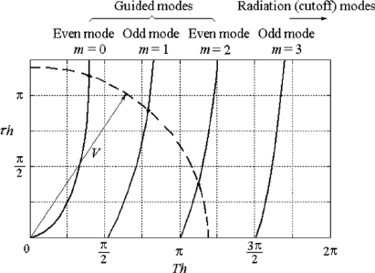
Figure 6.3: Graphical solution of the eigenvalue equations for the symmetrical
planar dielectric waveguide.
6.2.3 Cutoff Condition, Guided Modes and Radiation
Modes
Either the eigenvalue equation for TM modes (6.72) or that for TE modes
(6.93) individually combined with (6.73) can be solved to give the transverse
angular wave number in the core, T , and that outside the core, τ, in terms
of the angular frequency ω. These equations can be solved graphically as
shown in Fig. 6.3. The curves representing (6.72) or (6.93) for given modes
are plotted as solid lines and the curve representing (6.73) is plotted as a
dashed line, which is exactly a quadrant of a circle. The intersections of
the two sets of curves are the solutions of the two equations, which give T h
and τ h for given ω for guided modes. We can see from the figure that the
higher the frequency, the larger the circle, and we have more intersection
points. This means that more modes are guided modes when the frequency
becomes higher. The modes that have no intersection with the circle are
radiation modes; in other words, for those modes, the transverse angular wave
numbers outside the core are imaginary, τ = jk
x
, therefore the transverse
dependent parts of the fields become traveling waves e
±jk
x
x
. Such modes
are radiation modes. For radiation modes, accompanied with the radiation
in the transverse direction, which leads to power losses, the waves in the
longitudinal direction will be attenuated. The lower limit in the frequency
of a certain mode as a guided mode is known as the cutoff frequency and is
denoted by ω
c
. Note that the physical meaning of “cutoff” for a dielectric
waveguide is entirely different from that for a metallic waveguide. When
the frequency is lower than the cutoff frequency of a certain mode, decaying
fields along the longitudinal direction in a metallic waveguide cause no power

6.2 Symmetrical Planar Dielectric Waveguides 333
loss. Such modes are known as the cutoff modes or evanescent modes. But
in dielectric waveguides, when the frequency is lower than the cutoff value,
the modes become radiation modes and the slab becomes a radiator. For
a dielectric waveguide operating at a certain frequency, a finite number of
guided modes and an infinite number of radiation modes exist in it.
The cutoff condition for a dielectric waveguide is τ = 0. From (6.72) and
(6.93), we get the cutoff condition for even TM and TE modes:
τh = 0, tan T h = 0, T h =
mπ
2
, m = 0, 2, 4, 6, ···.
Similarly, we get the cutoff condition for odd TM and TE modes:
τh = 0, cot T h = 0, T h =
mπ
2
, m = 1, 3, 5, ···.
Using (6.73), we obtain the expression for the cutoff frequency
T
c
h =
mπ
2
= ω
c
h
√
µ
1
²
1
− µ
2
²
2
, ω
c
=
mπ
2h
√
µ
1
²
1
− µ
2
²
2
. (6.97)
The cutoff conditions for TE modes and TM modes of the same order
are the same but the corresponding eigenvalue equations, i.e., the dispersion
characteristics, are different from each other. Thus they are not degenerate
modes.
6.2.4 Dispersion Characteristics of Guided Modes
The longitudinal phase coefficient of a guided mode, β, is determined by
(6.62) when τ and T for a given ω are found. Then the dispersion curves,
i.e., ω–β or k–β diagrams, are plotted as shown in Fig. 6.4(a). The dispersion
curves for all modes are limited in an interval set by the lower bound β =
ω
√
µ
2
²
2
and the upper bound β = ω
√
µ
1
²
1
. At the cutoff frequency, ω →
ω
c
, the longitudinal phase coefficient β approaches its lower bound which
corresponds to k
2
. At the same time v
p
→ 1/
√
µ
2
²
2
, i.e., the phase velocity
of the guided wave approaches that of the plane wave in the medium of
the cladding. This corresponds to the critical angle of incidence of a plane
wave on the boundary. As the frequency increases, the longitudinal phase
coefficient β approaches its upper bound that corresponds to k
1
. At the same
time v
p
→ 1/
√
µ
1
²
1
, i.e., the phase velocity of the guided wave becomes that
of the plane wave in the medium in the core. This is the situation of 90
◦
incidence of the plane wave on the boundary, i.e., the incident wave vector is
parallel to the boundary. As the frequency increases, more and more guided
modes propagate in the slab.
In most optical waveguides, µ
1
²
1
is very close to µ
2
²
2
. In this case, the
dispersion curves are limited in a very narrow interval and are therefore
difficult to read. To obtain a more convenient scaled diagram that shows the
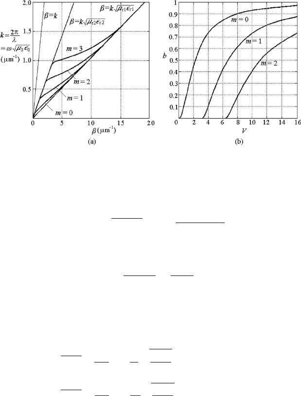
334 6. Dielectric Waveguides and Resonators
Figure 6.4: Dispersion curves of the symmetrical planar dielectric waveguide.
ω–β relationship, we define a normalized frequency V by
V = h
q
k
2
1
− k
2
2
= ωh
√
µ
1
²
1
− µ
2
²
2
, (6.98)
and a normalized guided index b by
b =
β
2
− k
2
2
k
2
1
− k
2
2
=
(τh)
2
V
2
. (6.99)
The index b is zero at cutoff and approaches unity at values far away from
cutoff.
Then the eigenvalue equations for TM modes (6.72) and TE modes (6.93)
become
tan
³
V
√
1 − b −
mπ
2
´
=
²
1
²
2
r
b
1 − b
, for TM modes, (6.100)
tan
³
V
√
1 − b −
mπ
2
´
=
µ
1
µ
2
r
b
1 − b
, for TE modes. (6.101)
The normalized dispersion curves of b versus V are shown in Fig. 6.4(b).
6.2.5 Radiation Modes
It may be recalled from Section 5.1 that in metallic waveguides, there can be
a finite number of guided modes and an infinite number of cutoff modes or
evanescent modes. The characteristic impedance of a cutoff mode is reactive,
so the property of any discontinuity in a metallic waveguide in which higher
evanescent modes are excited is reactive and gives rise to reflection of waves.
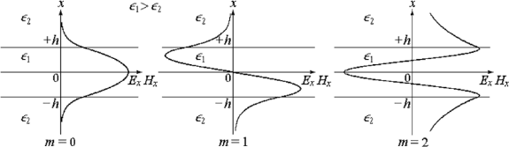
6.2 Symmetrical Planar Dielectric Waveguides 335
Figure 6.5: Transverse dependence of fields in a symmetrical planar dielectric
waveguide.
In a dielectric waveguide, all modes with a cutoff frequency higher than
the operating frequency become radiation modes. In any dielectric waveguide,
for any operating frequency, there must exist a finite number of guided modes
and an infinite number of radiation modes. When a dielectric waveguide is
excited by a source, or a imperfection or discontinuity is located in the guide,
all guided modes and radiation modes are excited to satisfy the boundary
conditions of the waveguide and the source or discontinuity. Guided modes
propagate along the guide a long way, whereas radiation modes radiate in the
transverse direction and are attenuated in the longitudinal direction. This
phenomenon gives rise to loss of energy.
For example, a bend in a metallic waveguide gives rise to reflection but in
a dielectric waveguide it gives rise to bending loss if the radius of curvature
is sufficiently small. If the waveguide is uniform and infinitely long and the
source is located at plus or minus infinity, then only guided modes exist in
the guide; the same is true in metallic waveguides.
6.2.6 Fields in Symmetrical Planar Dielectric
Waveguides
The x dependencies of the transverse field components of guided modes and
radiation modes in a symmetrical dielectric slab waveguide are illustrated
in Fig. 6.5. For guided modes, the fields are standing waves along x in the
core and are decaying fields along ±x in the cladding, whereas for radiation
modes, the fields are radiation waves along ±x in the cladding.
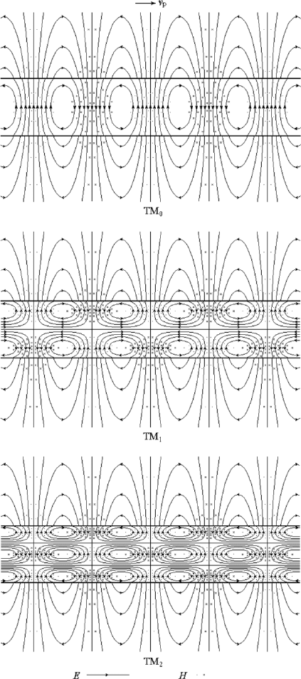
The field maps of some low-order TM and TE guided modes are given in
Fig. 6.6 and Fig. 6.7, respectively. We easily see that the fields in the central
part of the slab are similar to those in the metallic parallel-plate line shown
in Figure 5.14, and the fields at the boundary and in the cladding are the
same as those for the total internal reflection shown in Fig. 2.20.
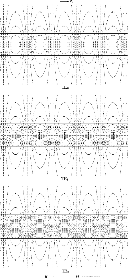
336 6. Dielectric Waveguides and Resonators
Figure 6.6: Field maps of some low-order guided TE modes in symmetrical
planar dielectric waveguide.
6.2 Symmetrical Planar Dielectric Waveguides 337
Figure 6.7: Field maps of some low-order guided TM modes in symmetrical
planar dielectric waveguide.

338 6. Dielectric Waveguides and Resonators
6.2.7 The Dominant Modes in Symmetrical Planar
Dielectric Waveguides
The lowest mode or dominant mode in a symmetrical planar dielectric waveg-
uide are TE or TM modes with m = 0. According to (6.97), the cutoff
frequencies are consequently zero for these modes:
ω
c
=
mπ
2h
√
µ
1
²
1
− µ
2
²
2
m=0
= 0.
These TM
0
and TE
0
modes remain guided modes down to zero frequency.
This feature of the lowest modes in a dielectric waveguide is shared by the
TEM mode in a two-conductor transmission line.
For TM
0
and TE
0
modes, if the operating frequency is so low that τ → 0
and T → 0, then from the field-component expressions (6.51) to (6.53) and
(6.78) to (6.80), we notice that the longitudinal components are much smaller
than the transverse components. The field expressions in the core reduce to
E
x1
=E
0
e
−jβz
, H
y 1
=
ω²
1
β
E
0
e
−jβz
=
E
0
η
1
e
−jβz
, for TM
0
mode, (6.102)
E
y 1
=E
0
e
−jβz
, H
x1
=−
β
ωµ
1
E
0
e
−jβz
=−
E
0
η
1
e
−jβz
, for TE
0
mode. (6.103)
The fields of TM
0
and TE
0
modes in the core asymptotically approach those
of the uniform plane wave or the TEM mode in a parallel-plate transmission
line, as the frequency decreases to zero.
6.2.8 The Weekly Guiding Dielectric Waveguides
In typical dielectric waveguides for optical frequencies, the refractive index of
the core is only slightly larger than that of the cladding, (n
1
−n
2
)/n
1
¿ 1, so
that n
1
≈ n
2
. The difference between the indices of the core and the cladding
is less than a few percent. This is the weakly guiding condition, and this kind
of optical waveguide is known as the weakly guiding optical waveguide.
For weakly guiding optical waveguides, the critical angle on the boundary
is rather large. For guided modes, the angle of incidence must b e larger than
the critical angle and close to π/2, i.e. the wave vector of the incident wave
is almost parallel to the z axis. In this case, the longitudinal components of
the fields are much less than the transverse components, and the longitudinal
wave number is approximately equal to the wave number of a plane wave in
the core material, that is to say, the wave is close to the TEM mode. This
kind of modes are known as quasi-TEM modes.
For non-magnetic dielectric waveguides, µ
1
= µ
2
= µ
0
, the eigenvalue
equation for TE modes, (6.93) becomes
T h tan
³
T h −
mπ
2
´
= τh.
6.3 Dielectric Coated Conductor Plate 339
Figure 6.8: Dielectric coated conducting plate.
For weekly-guiding dielectric waveguides, ²
1
≈ ²
2
, the approximate eigenvalue
equation for TM modes, (6.72) becomes
T h tan
³
T h −
mπ
2
´
= τh,
We see that, for weekly guiding dielectric waveguides, the TE
m
mode and
TM
m
mode are approximately degenerate modes.
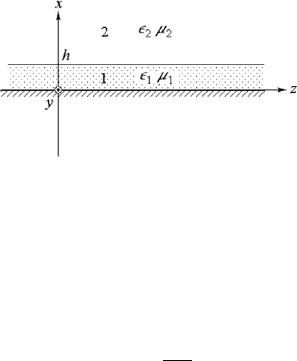
6.3 Dielectric Coated Conductor Plate
The dielectric coated conducting plate shown in Fig. 6.8, is also known as
the dielectric image waveguide. The analysis of a dielectric coated conduct-
ing plate is similar to that of the symmetrical dielectric slab waveguide. By
imposing the short-circuit boundary condition at x = 0, we deduce that only
even TM modes and odd TE modes can exist in a dielectric coated conduct-
ing plate, i.e., TM
0
, TM
2
, TM
4
, ··· and TE
1
, TE
3
, TE
5
, ··· modes remain
nontrivial. The propagation characteristics and field distribution for the di-
electric coated conducting plate are the same as those for the corresponding
modes in symmetrical dielectric slab waveguide.
The dielectric coated conducting plate can be used as a slow-wave struc-
ture, and the equivalent metallic structure will be introduced in the next
chapter.
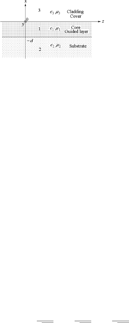
6.4 Asymmetrical Planar Dielectric
Waveguides
In the optical waveband, especially in integrated optics applications, the com-
monly used waveguide is the asymmetrical planar dielectric waveguide shown
in Fig. 6.9, where the core, a planar film of refractive index n
1
, is sandwiched
between a substrate of refractive index n
2
and a cladding or cover of refractive
index n
3
. In order to support guided modes it is necessary to make n
1
> n
2
340 6. Dielectric Waveguides and Resonators
Figure 6.9: Asymmetrical planar dielectric waveguide.
and n
1
> n
3
. Sometimes the cladding material is nothing but air, in which
case n
3
= 1. The dielectric waveguide is usually fabricated by growing thin
film on substrate such as glass, crystal, or semiconductor material. The film
can be deposited by evaporation or sputtering, or done by means of epitax-
ial growth techniques. Alternatively, dielectric optical waveguide fabrication
employs doping techniques including proton exchange, diffusion and ion im-
plantation techniques. Typical differences between the indices of the core
and the substrate range from 10
−3
to 10
−1
, and the typical film thickness is
in the micrometer range. In the guided mode the wave is confined in the core
or so-called guided layer by total internal reflection at the core–substrate and
core–cladding boundaries.
Suppose the permittivity and permeability are ²
1
, µ
1
for the material
of the core, region 1, ²
2
, µ
2
for the substrate, region 2, and ²
3
, µ
3
for the
cladding, region 3. The thickness of the core is d in the x direction and the
waveguide extends to infinity in the y and z directions; refer to Fig. 6.9.
For guided modes, the field dependence in the guided layer is a standing
wave in the x direction with phase coefficient T , and the fields in the substrate
and the cladding are decaying fields in the transverse directions with decaying
coefficients τ
2
and τ
3
, respectively. The longitudinal dependencies of the field
in all the three regions are traveling waves with the same phase coefficient
β, as required by the boundary conditions. The relations among the phase
coefficients and decaying coefficients are as follows:
β
2
+T
2
=k
2
1
=ω
2
µ
1
²
1
, β
2
−τ
2
2
=k
2
2
=ω
2
µ
2
²
2
, β
2
−τ
2
3
=k
2
3
=ω
2
µ
3
²
3
,
which lead to
β
2
= k
2
1
− T
2
= k
2
2
+ τ
2
2
= k
2
3
+ τ
2
3
. (6.104)
This implies that
β < k
1
, β >k
2
, β >k
3
, v
p
>
1
√
µ
1
²
1
, v
p
<
1
√
µ
2
²
2
, v
p
<
1
√
µ
3
²
3
. (6.105)