Zhang K., Li D. Electromagnetic Theory for Microwaves and Optoelectronics
Подождите немного. Документ загружается.

6.6 Circular Dielectric Waveguides and Optical Fibers 361
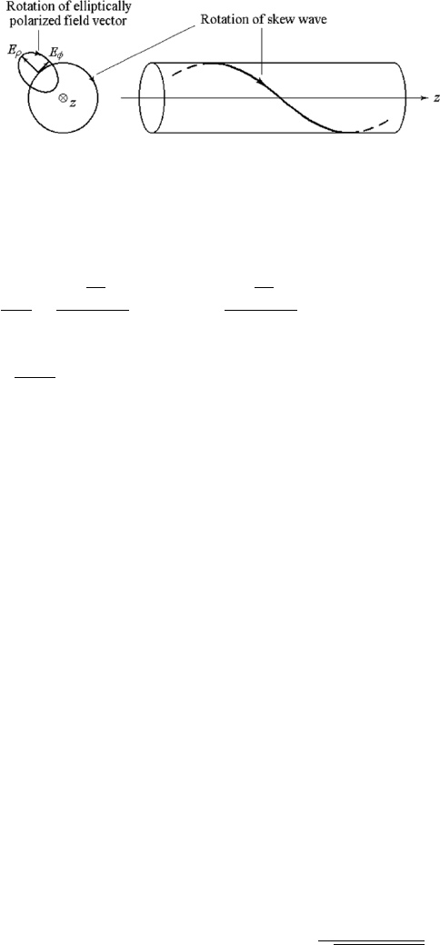
Figure 6.18: Rotation of skew wave and the rotation of polarized field vector
in circular dielectric waveguide.
H
φ2
= j
β
2
τ
ωµ
0
C
χ+
k
2
β
2
²
r2
2
K
n+1
(τρ)−
χ−
k
2
β
2
²
r2
2
K
n−1
(τρ)
e
jnφ
e
−jβz
, (6.228)
H
z2
= −j
τ
2
βχ
ωµ
0
CK
n
(τρ)e
jnφ
e
−jβz
. (6.229)
By investigating the relations between the transverse components, E
ρ
and
E
φ
or H
ρ
and H
φ
, we find that the transverse field vector is elliptically polar-
ized, consisting of two circularly polarized components in opposite directions.
In the above expressions, n is an integer or zero. The modes with n = 0
represent axially symmetric modes or meridional waves. The modes with
n 6= 0 represents axially asymmetric modes or skew waves or circulating
waves. The modes with positive and negative n represent counterclockwise
and clockwise, i.e., left-handed and right-handed skew waves, respectively.
Note that the direction of rotation of skew waves and the direction of rota-
tion of polarized field vectors are entirely different phenomena, see Fig. 6.18.
From the eigenvalue equation (6.210) or (6.212) we can see that, the
cutoff conditions and the dispersion relations are the same for +n and −n,
τ
−n
= τ
+n
and β
−n
= β
+n
. So the clo ckwise and counterclockwise skew
waves with functions e
−jnφ
e
−jβ
−n
z
and e
jnφ
e
−jβ
n
z
can be composed into two
mutually orthogonal angular standing waves sin(nφ)e
−jβ
n
z
and cos(nφ)e
−jβ
n
z
with stationary polarization direction. This is the same as that for all waveg-
uides made by isotropic material and isotropic boundaries.
(2) Solutions to the Eigenvalue Equation
The cutoff condition of the uniform circular dielectric waveguide is τ = 0 and
T = T
c
. Applying this condition in (6.212), we have T
c
. Then the cutoff
angular frequency can be obtained from (6.213) as follows:
T
2
c
= k
2
1
− k
2
2
= ω
2
c
(µ
1
²
1
− µ
2
²
2
), ω
c
=
T
c
√
µ
1
²
1
− µ
2
²
2
. (6.230)
362 6. Dielectric Waveguides and Resonators
If the operating frequency ω is higher than the cutoff frequency ω
c
, then
T
2
< T
2
c
, τ
2
> 0, and τ is real. In this case, the radial dependencies of the
fields in the cladding are modified Bessel functions of the second kind, which
means that the fields are decaying functions with respect to ρ and traveling
waves along z. This is the guided mode.
If the operating frequency ω is lower than the cutoff frequency ω
c
, then
T
2
> T
2
c
, τ
2
< 0, and τ is imaginary. In this case, the radial dependencies
of the fields in the cladding are mo dified Bessel functions of the second kind
with imaginary arguments which reduce to Hankel functions of the second
kind representing outward traveling waves. This is the radiation mode. In
this case the dielectric rod or wire is acting as a cylindrical antenna and the
energy radiates outward from its side.
The eigenvalue equation (6.212) can be reduced to the following quadratic
equation in J
0
n
(T a)/T aJ
n
(T a):
·
J
0
n
(T a)
T aJ
n
(T a)
¸
2
+
·
²
1
µ
2
+²
2
µ
1
²
1
µ
1
K
0
n
(τa)
τaK
n
(τa)
¸
J
0
n
(T a)
T aJ
n
(T a)
+
²
2
µ
2
²
1
µ
1
·
K
0
n
(τa)
τaK
n
(τa)
¸
2
− n
2
·
1
(T a)
2
+
1
(τa)
2
¸·
1
(T a)
2
+
²
2
µ
2
²
1
µ
1
(τa)
2
¸
=0. (6.231)
The roots of this quadratic equation are as follows:
J
0
n
(T a)
T aJ
n
(T a)
= −P +
√
R, for EH modes, (6.232)
J
0
n
(T a)
T aJ
n
(T a)
= −P −
√
R, for HE modes, (6.233)
where
P =
²
1
µ
2
+ ²
2
µ
1
2²
1
µ
1
K
0
n
(τa)
τaK
n
(τa)
,
R=
µ
²
1
µ
2
−²
2
µ
1
2²
1
µ
1
2
·
K
0
n
(τa)
τaK
n
(τa)
¸
2
+n
2
·
1
(T a)
2
+
1
(τa)
2
¸·
1
(T a)
2
+
²
2
µ
2
²
1
µ
1
(τa)
2
¸
.
Equations (6.232) and (6.233) can be solved graphically by plotting b oth
sides as functions of T a, using (6.213) on the right-hand side, i.e.,
τa =
p
(k
1
a)
2
−(k
2
a)
2
−(T a)
2
=
p
ω
2
a(²
1
µ
1
−²
2
µ
2
)−(T a )
2
=
p
V
2
−(T a)
2
.
The eigenmodes in circular dielectric waveguides are TE
0m
modes, TM
0m
modes and HEM
nm
modes; the HEM
nm
modes in turn can be classified as
EH
nm
and HE
nm
modes. We will see later that the modes are TE
0m
or
EH
nm
if we choose the plus sign on the radical, i.e., (6.232), whereas the
modes are TM
0m
or HE
nm
if we choose the minus sign on the radical, i.e.,
(6.233) .
6.6 Circular Dielectric Waveguides and Optical Fibers 363
(3) Circularly Symmetric Modes, TE and TM Modes
In a uniform circular dielectric waveguide, pure TE or TM modes exist only
when the fields in the transverse section are circularly symmetrical, i.e.,
∂/∂φ = 0, which corresponds to meridional rays, n = 0.
(a) Eigenvalue Equations and Their Graphical Solutions. Consid-
ering the following relations:
J
0
0
(x) = −J
1
(x), K
0
0
(x) = −K
1
(x).
The eigenvalue equation (6.210) or (6.212) for n = 0 can be reduced to
·
²
1
J
1
(T a)
T aJ
0
(T a)
+ ²
2
K
1
(τa)
τaK
0
(τa)
¸·
µ
1
J
1
(T a)
T aJ
0
(T a)
+ µ
2
K
1
(τa)
τaK
0
(τa)
¸
= 0. (6.234)
This can be separated into the following two eigenvalue equations:
J
1
(T a)
J
0
(T a)
= −
µ
2
µ
1
T aK
1
(τa)
τaK
0
(τa)
, for TE modes, (6.235)
J
1
(T a)
J
0
(T a)
= −
²
2
²
1
T aK
1
(τa)
τaK
0
(τa)
, for TM modes. (6.236)
These two equations can also be obtained from (6.232) and (6.233) by letting
n = 0.
For circularly symmetrical modes, equations (6.215) and (6.217) become
χ =
ω
√
µ
0
²
0
β
r
²
r1
J
1
(T a)
T aJ
0
(T a)
+
²
r2
K
1
(τa)
τaK
0
(τa)
r
µ
r1
J
1
(T a)
T aJ
0
(T a)
+
µ
r2
K
1
(τa)
τaK
0
(τa)
,
H
z
E
z
=
jβχ
ωµ
0
.
It is clear that for modes satisfying eigenvalue equation (6.235),
χ → ∞, E
z
= 0,
which corresponds to EH
0m
or TE
0m
modes. For mo des satisfying eigenvalue
equation (6.236),
χ = 0, H
z
= 0,
which corresponds to HE
0m
or TM
0m
modes.
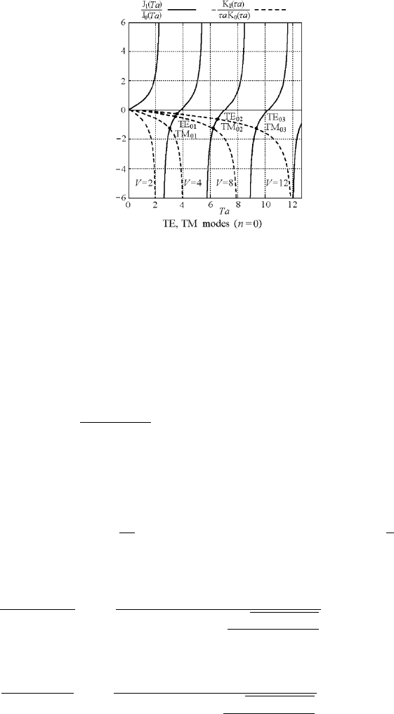
We now consider the graphical solution of (6.235) and (6.236); refer
to Fig. 6.19. On the left-hand side of (6.235) and (6.236), the function
J
1
(T a)/J
0
(T a) starts from 0 at T a = 0 and increases monotonically un-
til it diverges to ∞ at the first zero of J
0
(T a) i.e., T a = 2.405. Beyond
T a = 2.405, J
1
(T a)/J
0
(T a) varies from −∞ to +∞ between the zeros of
364 6. Dielectric Waveguides and Resonators
Figure 6.19: Graphical determination of the eigenvalues of TE and TM modes
in circular dielectric waveguide.
J
0
(T a). For large values of T a, the multi-branched function J
1
(T a)/J
0
(T a)
asymptotically varies like −tan(T a − π/4).
For the functions on the right-hand side of (6.235) and (6.236), the guided
modes or confined mo des require that τ has to be real to achieve the ex-
ponential decay of the fields in the cladding. Correspondingly, (τa)
2
is
never negative and, according to (6.213), T a must satisfy 0 ≤ T a ≤ V ,
where V = ωa
√
µ
1
²
1
− µ
2
²
2
is the normalized frequency for circular dielec-
tric waveguides. The right-hand side of (6.235) or (6.236) is always negative
and is a monotonically decreasing function of T a. Both functions originate
from 0 at T a = 0, and, according to the following asymptotical expressions
of modified Bessel functions,
lim
x→0
K
0
(x) = ln
2
γx
, where γ = 1.781, lim
x→0
K
1
(x) =
1
x
,
in the limiting case when τa → 0, the functions approach their limits
−
µ
2
T aK
1
(τa)
µ
1
τaK
0
(τa)
τa→0
−→
µ
2
T a
µ
1
[V
2
− (T a)
2
] ln
γ
p
V
2
− (T a)
2
2
, for TE modes,
or
−
²
2
T aK
1
(τa)
²
1
τaK
0
(τa)
τa→0
−→
²
2
T a
²
1
[V
2
− (T a)
2
] ln
γ
p
V
2
− (T a)
2
2
, for TM modes,
which diverges to −∞ at T a = V .
6.6 Circular Dielectric Waveguides and Optical Fibers 365
The eigenvalue equations (6.235) for TE modes and (6.236) for TM modes
are in the same form. The two curves describing the left-hand side and right-
hand side of either one of them are illustrated in Fig. 6.19. The intersections
of the two curves represent the guided modes in the waveguide. More inter-
sections show up, in other words, more modes become guided modes when
the frequency increases, i.e., the value of V increases.
(b) Cutoff Conditions for TE and TM Modes. The cutoff condition
for a dielectric waveguide is τ = 0. For n = 0, we have
lim
τa→0
τaK
0
(τa)
K
1
(τa)
= lim
τa→0
·
(τa)
2
ln
2
γτa
¸
= 0.
Hence the cutoff conditions for circularly symmetric modes are
µ
2
µ
1
T aJ
0
(T a)
J
1
(T a)
=0, for TE modes, (6.237)
or
²
2
²
1
T aJ
0
(T a)
J
1
(T a)
=0, for TM modes. (6.238)
The roots of these two equations are the same:
J
0
(T a) = 0, T
c
=
x
0m
a
, (6.239)
where x
0m
denotes the mth root of J
0
(x) = 0. The cutoff frequency of the
TM
0m
mode or the TE
0m
mode can then be obtained from (6.230):
ω
c
=
x
0m
a
√
µ
1
²
1
− µ
2
²
2
. (6.240)
Note that T a = 0 is not an acceptable solution of (6.238) and (6.237), because
lim
T a→0
J
1
(T a) =
1
2
T a = 0,
and
lim
T a→0
T aJ
0
(T a)
J
1
(T a)
= 2J
0
(0) 6= 0.
The cutoff conditions for the TM
0m
and TE
0m
modes are the same but
the eigenvalue equations, i.e., the dispersion characteristics, are different from
each other. They are not degenerate modes.
The lowest TM mode is TM
01
and the lowest TE mode is TE
01
, for which
x
01
= 2.405.
Neither the TM
01
mode nor the TE
01
mode is the lowest mode in circular
dielectric waveguide. The next two modes correspond to
x
02
= 5.520, x
03
= 8.654.
366 6. Dielectric Waveguides and Resonators
For higher modes, the asymptotic formula
x
0m
≈
µ
m −
1
4
π, for m ≥ 4,
gives values of the roots with adequate accuracy.
(c) Field Components of TM and TE Modes. For TM modes, n = 0,
V = 0. By applying (6.216), we find that the field components (6.191)–
(6.196) and (6.198)–(6.203) become
E
ρ1
= jβT AJ
1
(T ρ)e
−jβz
, (6.241)
E
z1
= T
2
AJ
0
(T ρ)e
−jβz
, (6.242)
H
φ1
= jω²
1
T AJ
1
(T ρ)e
−jβz
, (6.243)
E
ρ2
= jβτ CK
1
(τρ)e
−jβz
= −jβ
T
2
J
0
(T a)
τK
0
(τa)
AK
1
(τρ)e
−jβz
, (6.244)
E
z2
= −τ
2
CK
0
(τρ)e
−jβz
=
T
2
J
0
(T a)
K
0
(τa)
AK
0
(τρ)e
−jβz
, (6.245)
H
φ2
= jω²
2
τCK
1
(τρ)e
−jβz
= −jω²
2
T
2
J
0
(T a)
τK
0
(τa)
AK
1
(τρ)e
−jβz
. (6.246)
To satisfy the boundary conditions for E
z
and H
φ
on the boundary ρ = a,
the required eigenvalue equation for TM modes is just (6.236).
For TE modes, n = 0, U = 0. With the application of (6.216), the field
components (6.191)–(6.196) and (6.198)–(6.203) become
H
ρ1
= jβT BJ
1
(T ρ)e
−jβz
, (6.247)
H
z1
= T
2
BJ
0
(T ρ)e
−jβz
, (6.248)
E
φ1
= −jωµ
1
T BJ
1
(T ρ)e
−jβz
, (6.249)
H
ρ2
= jβτ DK
1
(τρ)e
−jβz
= −jβ
T
2
J
0
(T a)
τK
0
(τa)
BK
1
(τρ)e
−jβz
, (6.250)
H
z2
= −τ
2
DK
0
(τρ)e
−jβz
=
T
2
J
0
(T a)
K
0
(τa)
BK
0
(τρ)e
−jβz
, (6.251)
E
φ2
= −jωµ
2
τDK
1
(τρ)e
−jβz
= jωµ
2
T
2
J
0
(T a)
τK
0
(τa)
BK
1
(τρ)e
−jβz
. (6.252)
To satisfy the boundary conditions for E
φ
and H
z
on the boundary ρ = a,
the required eigenvalue equation for TE mode is just (6.235).
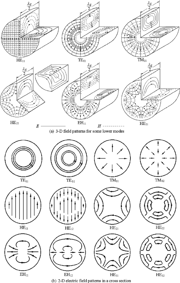
The field patterns of the TE
01
and TM
01
modes are shown in the center
and right of the first row in Fig. 6.20(a) [11]. The field patterns in the cross-
section of the TE
01
, TE
02
, TM
01
and TM
0m
modes are shown in the first
row of (b).
6.6 Circular Dielectric Waveguides and Optical Fibers 367
Figure 6.20: Field patterns of some lower modes in a circular dielectric waveg-
uide.
368 6. Dielectric Waveguides and Resonators
6.6.2 Nonmagnetic Circular Dielectric Waveguides
In most dielectric waveguides and optical fibers, both the core and the
cladding are made from nonmagnetic dielectric materials.
(1) Eigenvalue Equations
For a nonmagnetic dielectric waveguide or optical fiber, µ
1
= µ
2
= µ
0
, ²
1
6=
²
2
, the eigenvalue equation (6.212) becomes
·
²
1
J
0
n
(T a)
T aJ
n
(T a)
+ ²
2
K
0
n
(τa)
τaK
n
(τa)
¸·
J
0
n
(T a)
T aJ
n
(T a)
+
K
0
n
(τa)
τaK
n
(τa)
¸
− n
2
·
²
1
(T a)
2
+
²
2
(τa)
2
¸·
1
(T a)
2
+
1
(τa)
2
¸
= 0. (6.253)
From the differential formulas (C.16), (C.18) and recurrence formulas (C.13)
and (C.15) of Bessel functions, we get
J
0
n
(T a)
T aJ
n
(T a)
=
1
2
·
J
n−1
(T a)
T aJ
n
(T a)
−
J
n+1
(T a)
T aJ
n
(T a)
¸
=
1
2
(J
−
− J
+
), (6.254)
K
0
n
(τa)
τaK
n
(τa)
= −
1
2
·
K
n−1
(τa)
τaK
n
(τa)
+
K
n+1
(τa)
τaK
n
(τa)
¸
= −
1
2
(K
−
+ K
+
), (6.255)
n
(T a)
2
=
1
2
·
J
n−1
(T a)
T aJ
n
(T a)
+
J
n+1
(T a)
T aJ
n
(T a)
¸
=
1
2
(J
−
+ J
+
), (6.256)
n
(τa)
2
= −
1
2
·
K
n−1
(τa)
τaK
n
(τa)
−
K
n+1
(τa)
τaK
n
(τa)
¸
= −
1
2
(K
−
− K
+
), (6.257)
Substituting them into (6.253), we obtain
(²
1
J
+
+ ²
2
K
+
)(J
−
− K
−
) + (J
+
+ K
+
)(²
1
J
−
− ²
2
K
−
) = 0,
i.e.,
·
²
1
J
n+1
(T a)
T aJ
n
(T a)
+ ²
2
K
n+1
(τa)
τaK
n
(τa)
¸·
J
n−1
(T a)
T aJ
n
(T a)
−
K
n−1
(τa)
τaK
n
(τa)
¸
+
·
J
n+1
(T a)
T aJ
n
(T a)
+
K
n+1
(τa)
τaK
n
(τa)
¸·
²
1
J
n−1
(T a)
T aJ
n
(T a)
− ²
2
K
n−1
(τa)
τaK
n
(τa)
¸
= 0. (6.258)
This is the eigenvalue equation for nonmagnetic circular dielectric waveg-
uides. By using the Bessel function relations (6.254)–(6.257), we get
J
0
n
(T a)
T aJ
n
(T a)
=
n
(T a)
2
−
J
n+1
(T a)
T aJ
n
(T a)
= −
n
(T a)
2
+
J
n−1
(T a)
T aJ
n
(T a)
,
K
0
n
(τa)
τaK
n
(τa)
=
n
(τa)
2
−
K
n+1
(τa)
τaK
n
(τa)
= −
n
(τa)
2
−
K
n−1
(τa)
τaK
n
(τa)
,
6.6 Circular Dielectric Waveguides and Optical Fibers 369
then the two equations (6.232) and (6.233) become
J
n+1
(T a)
J
n
(T a)
= T a
·
P +
n
(T a)
2
−
√
R
¸
, for EH modes, (6.259)
and
J
n−1
(T a)
J
n
(T a)
= T a
·
−P +
n
(T a)
2
−
√
R
¸
, for HE modes, (6.260)
where P and R become
P =
²
²
1
K
0
n
(τa)
τaK
n
(τa)
=
²
²
1
·
n
(τa)
2
−
K
n+1
(τa)
τaK
n
(τa)
¸
=
²
²
1
·
−
n
(τa)
2
−
K
n−1
(τa)
τaK
n
(τa)
¸
,
R =
·
∆²
²
1
K
0
n
(τa)
τaK
n
(τa)
¸
2
+n
2
·
1
(T a)
2
+
1
(τa)
2
¸·
1
(T a)
2
+
²
2
²
1
(τa)
2
¸
=
½
∆²
²
1
·
n
(τa)
2
−
K
n+1
(τa)
τaK
n
(τa)
¸¾
2
+n
2
·
1
(T a)
2
+
1
(τa)
2
¸·
1
(T a)
2
+
²
2
²
1
(τa)
2
¸
=
½
∆²
²
1
·
−
n
(τa)
2
−
K
n−1
(τa)
τaK
n
(τa)
¸¾
2
+n
2
·
1
(T a)
2
+
1
(τa)
2
¸·
1
(T a)
2
+
²
2
²
1
(τa)
2
¸
,
with
² = (²
1
+ ²
2
)/2 and ∆² = (²
1
− ²
2
)/2.
We call the modes belonging to eigenvalue equation (6.259) EH modes
and the modes belonging to eigenvalue equation (6.260) HE modes. The
meaning of those names will be given later.
If n = 0, (6.259) and (6.260) reduce to (6.235) and (6.236), respectively,
with µ
1
= µ
2
= µ
0
. The solutions to the eigenvalue equations for circularly
symmetric modes have been given in the last subsection, now we will work
out the solutions to those for circularly asymmetric modes.
(2) Graphical Solutions to the Eigenvalue Equations
for Circularly Asymmetric Modes [48]
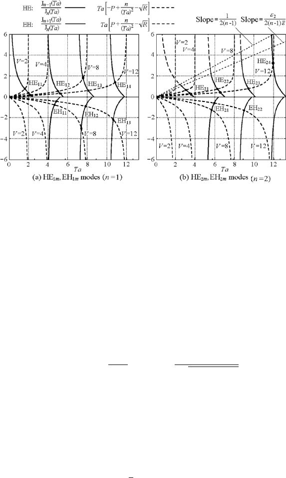
Equations (6.259) and (6.260) for n 6= 0 can still be solved graphically in a
manner similar to that outlined for the n = 0 case.
(a) n = 1: For n = 1, lines representing functions in T a on both sides of
(6.259) for EH
1m
modes are shown in the lower half of Fig. 6.21(a). These
lines are similar to those for TE and TM modes except that the vertical
asymptotes of the family of multi-branched lines which represent the function
on the left-hand side of (6.259) are given by the roots of J
1
(T a) = 0 instead
of J
0
(T a) = 0.
The upper half of Fig. 6.21(a) shows the lines representing functions in T a
on both sides of (6.260) for HE
1m
modes. Note that the vertical asymptotes
370 6. Dielectric Waveguides and Resonators
Figure 6.21: Graphical determination of the eigenvalues of some lower EH
and HE modes in circular dielectric waveguide.
of the family of lines which represent the function on the left-hand side of
(6.260) are given by the roots of J
1
(T a) = 0 as well as T a = 0, and that
the function on the right-hand side of (6.260) is always positive and is a
monotonically increasing function of T a.
By examining Fig. 6.21(a), we find that the first intersection, i.e., the
guided-mode solution for the HE
11
mode always exists regardless of the value
of V . In other words, the HE
11
mode does not have any cutoff and can be a
guided mode even if the frequency is close to zero. All other cutoff values of
T
c
and ω
c
for EH
1m
and HE
1m
modes are given by
J
1
(T a) = 0, T
c
=
x
1m
0
a
, ω
c
=
x
1m
0
a
√
µ
1
²
1
− µ
2
²
2
, (6.261)
where x
1m
0
denotes the m
0
th ro ot of J
1
(x) = 0, while m
0
= m for the EH
1m
and m
0
= m − 1 for HE
1m
modes. For the HE
11
mode, T a = 0 and ω
c
= 0.
The first three zeros of J
1
(T a) are
x
11
= 3.832, x
12
= 7.016, x
13
= 10.173.
For higher zeros, the asymptotic formula
x
1m
≈
µ
m +
1
4
π, for m ≥ 4,
gives roots with adequate accuracy, because for large values of T a, the
functions J
2
(T a)/T aJ
1
(T a) and J
0
(T a)/T aJ
1
(T a) behaves very much like
±cot(T a − π/4)/T a.