Zhang K., Li D. Electromagnetic Theory for Microwaves and Optoelectronics
Подождите немного. Документ загружается.


6.6 Circular Dielectric Waveguides and Optical Fibers 381
+J
n−1
(T ρ)
½
sin (n −1)φ
−cos (n − 1)φ
¾¸
e
−jβz
, (6.292)
H
x1
=
¡
k
2
1
− k
2
x1
¢
V
(x)
1
≈ k
2
1
AJ
n
(T ρ)
½
cos nφ
sin nφ
¾
e
−jβz
, (6.293)
H
z1
=
∂
2
V
(x)
1
∂z ∂x
= j
βT
2
A
·
J
n+1
(T ρ)
½
cos (n + 1)φ
sin (n + 1)φ
¾
−J
n−1
(T ρ)
½
cos (n − 1)φ
sin (n −1)φ
¾¸
e
−jβz
, (6.294)
In region 2, the cladding, to avoid singularity as ρ → ∞, the functions in
ρ must be modified Bessel functions of the second kind. The functions in φ
are the same as those in the core. So the function V
(x)
2
is given by
V
(x)
2
=BK
n
(τρ)
½
cos nφ
sin nφ
¾
e
−jβz
. (6.295)
Substituting (6.295) into the field component expressions and using the
recurrence formula (C.15) and differential formula (C.18), we obtain the field
components of the linearly polarized modes in the cladding:
E
y 2
= −jωµ
0
∂V
(x)
2
∂z
= −ωµ
0
βBK
n
(τρ)
½
cos nφ
sin nφ
¾
e
−jβz
, (6.296)
E
z2
= jωµ
0
∂V
(x)
2
∂y
= −j
ωµ
0
τ
2
B
·
K
n+1
(τρ)
½
sin (n + 1)φ
−cos (n + 1)φ
¾
−K
n−1
(τρ)
½
sin (n −1)φ
−cos (n − 1)φ
¾¸
e
−jβz
, (6.297)
H
x2
=
¡
k
2
2
− k
2
x2
¢
V
(x)
2
≈ k
2
1
BK
n
(τρ)
½
cos nφ
sin nφ
¾
e
−jβz
, (6.298)
H
z2
=
∂
2
V
(x)
2
∂z ∂x
= j
βτ
2
B
·
K
n+1
(τρ)
½
cos (n + 1)φ
sin (n + 1)φ
¾
+K
n−1
(τρ)
½
cos (n − 1)φ
sin (n −1)φ
¾¸
e
−jβz
, (6.299)
The boundary conditions for the tangential field components are
E
y 1
(a) cos φ = E
y 2
(a) cos φ, H
x1
(a) sin φ = H
x2
(a) sin φ, (6.300)
E
z1
(a, φ) = E
z2
(a, φ), H
z1
(a, φ) = H
z2
(a, φ). (6.301)
The solutions of these boundary equations are
B =
J
n
(T a)
K
n
(T a)
A (6.302)
382 6. Dielectric Waveguides and Resonators
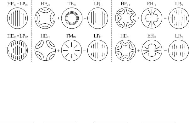
Figure 6.24: Field patterns of some linearly polarized modes in the core of
the weakly guiding optical fiber.
and the eigenvalue equations
T aJ
n+1
(T a)
J
n
(T a)
=
τaK
n+1
(τa)
K
n
(τa)
,
T aJ
n−1
(T a)
J
n
(T a)
= −
τaK
n−1
(τa)
K
n
(τa)
. (6.303)
By using the recurrence formulas of Bessel functions and modified Bessel
functions, we can prove that the above two equations are identical to each
other. The resulting eigenvalue equations are the same as the universal eigen-
value equation for a weakly guiding waveguide (6.286).
Similarly, it takes only a little effort to obtain also the solutions of the
modes with transverse electric field in the x direction.
The linearly polarized modes in a weakly guiding optical fiber are denoted
by LP
nm
, where m means that the mth root of the eigenvalue equation is
taken. The field patterns of some lower-order linearly polarized modes are
given in Fig. 6.24. We easily see that the LP
0m
mode is just the HE
1m
mode,
the LP
1m
mode is the superposition of HE
2m
and TE
0m
or TM
0m
modes, and
the other LP modes are the superposition of HE
n+1,m
and EH
n−1,m
modes.
The linearly polarized modes are merely approximations in the weakly
guiding condition. In fact, the longitudinal wave numbers of the two modes
elliptically polarized in opposite senses are not exactly the same, so the com-
posed mode will not remain linearly polarized forever during the propagation.
Only the LP
0m
modes, i.e., HE
1m
modes, are truly linearly polarized modes.
6.6.5 Dominant Modes in Circular Dielectric
Waveguides
The lowest mode, i.e., dominant mode, in a circular dielectric waveguide is
the HE
11
mode with zero cutoff frequency. The HE modes with n = 1 and
n = −1 represent two skew waves circularly polarized in opposite senses with
equal phase coefficients. The superposition of these two waves with equal
amplitudes results in a linearly polarized wave, i.e., the LP
01
mode.

6.6 Circular Dielectric Waveguides and Optical Fibers 383
For a weekly guiding optical fiber made of nonmagnetic material, µ
1
=
µ
2
= µ
0
, ²
1
≈ ²
2
, and β ≈ k
1
. Field components (6.218)–(6.223) become
n = +1, χ = −1 n = −1, χ = +1
E
ρ1
= −jk
1
T AJ
0
(T ρ)e
jφ
e
−jβz
, jk
1
T AJ
0
(T ρ)e
−jφ
e
−jβz
,
E
φ1
= k
1
T AJ
0
(T ρ)e
jφ
e
−jβz
, k
1
T AJ
0
(T ρ)e
−jφ
e
−jβz
,
E
z1
= T
2
AJ
1
(T ρ)e
jφ
e
−jβz
, −T
2
AJ
1
(T ρ)e
−jφ
e
−jβz
,
H
ρ1
= −(k
1
/η
1
)T AJ
0
(T ρ)e
jφ
e
−jβz
, −(k
1
/η
1
)T AJ
0
(T ρ)e
−jφ
e
−jβz
,
H
φ1
= −j(k
1
/η
1
)T AJ
0
(T ρ)e
jφ
e
−jβz
, j(k
1
/η
1
)T AJ
0
(T ρ)e
−jφ
e
−jβz
,
H
z1
= −j(1/η
1
)T
2
AJJ
1
(T ρ)e
jφ
e
−j6βz
, −j(1/η
1
)T
2
AJ
1
(T ρ)e
−jφ
e
−jβz
.
The superposition of the corresponding field components with n = +1 and
n = −1 is done by using simple mathematics so that
E
ρ1
= 2k
1
T AJ
0
(T ρ) sinφ e
−jβz
, (6.304)
E
φ1
= 2k
1
T AJ
0
(T ρ) cosφ e
−jβz
, (6.305)
E
z1
= j2T
2
AJ
1
(T ρ) sinφ e
−jβz
, (6.306)
H
ρ1
= −2
k
1
η
1
T AJ
0
(T ρ) cosφ e
−jβz
, (6.307)
H
φ1
= 2
k
1
η
1
T AJ
0
(T ρ) sinφ e
−jβz
, (6.308)
H
z1
= −j2
1
η
1
T
2
AJ
1
(T ρ) cosφ e
−jβz
. (6.309)
With the coordinate transformation
ˆ
xA
x
=
ˆ
ρA
ρ
cos φ −
ˆ
φA
φ
sin φ,
ˆ
yA
y
=
ˆ
ρA
ρ
sin φ +
ˆ
φA
φ
cos φ,
the cartesian components of the fields can be expressed by
E
y 1
= E
0
J
0
(T ρ) e
−jβz
, (6.310)
E
z1
= j
T
k
1
E
0
J
1
(T ρ) sin φ e
−jβz
, (6.311)
H
x1
= −
1
η
1
E
0
J
0
(T ρ) e
−jβz
, (6.312)
H
z1
= −j
T
ωµ
0
E
0
J
1
(T ρ) cos φ e
−jβz
, (6.313)
where E
0
= 2k
1
T A. The above expressions can be verified by checking them
against the field components of linearly polarized modes (6.291)–(6.294).
In weakly guiding waveguides, the wave propagates in a direction almost
parallel to the axis z. Hence T ¿ β, τ ¿ β, and β ≈ k
1
. It follows that in
this case, E
z1
¿ E
y 1
and H
z1
¿ H
x1
and the field components become
E
y 1
= E
0
e
−jβz
, H
x1
= −
1
η
1
E
0
e
−jβz
, and
|E
y 1
|
|H
x1
|
= η
1
.
Evidently the fields in the core are similar to those of plane waves.
384 6. Dielectric Waveguides and Resonators
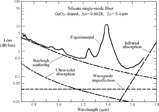
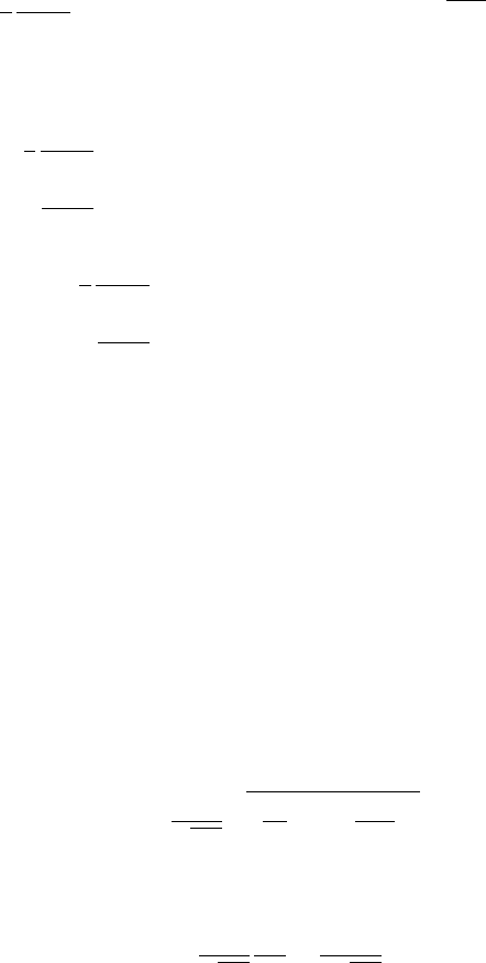
Figure 6.25: Measured loss spectrum of a germano-silicate single-mode opti-
cal fiber.
6.6.6 Low-Attenuation Optical Fiber
The present worldwide effort devoted to optical fiber communications systems
stems largely from two papers [47] [109] published in 1966, proposing that
optical fibers be used as dielectric waveguide in telecommunications to replace
coaxial line transmission systems. It is interesting to note how close the
optical fiber communication systems developed in recent years are to those
original proposals.
The key to the success in the application of optical fiber as the transmis-
sion medium in communication is to attain the low losses in light propagation.
Glass that is routinely used in optical instruments is far too lossy to be used
for optical fibers suitable for long-distance transmission. The attenuation
coefficient of optical fibers made by such glasses is about 1 dB/m, i.e., 1000
dB/km. That is to say, the power is attenuated to 10
−100
of the initial value
after 1 km, which is too bad to be acceptable for optical communication
purposes.
In 1970s the weakly guiding fiber made from very low OH contents
germania-doped fused silica by the chemical vapor deposition technique was
developed. The attenuation co efficient was made as low as 20 dB/km so that
optical fiber communication began to be practical.
Today, the single-mode germania-doped silicate optical fiber operated at
HE
11
mode has become the most important transmission medium in world-
wide networks for long-distance communications. The curve in Fig. 6.25
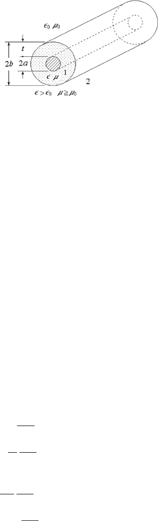
6.7 Dielectric-Coated Conductor Cylinder 385
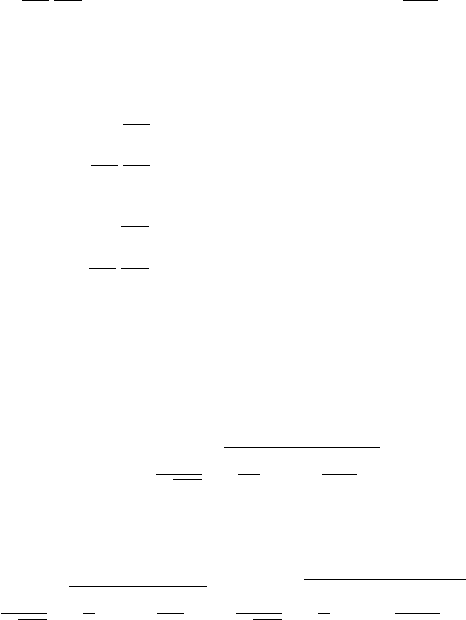
Figure 6.26: Dielectric-coated conducting cylinder.
shows the loss versus wavelength relationship of a mo dern optical fiber. The
curve shows that the loss peak around 1.4 µm is due to the residual OH con-
tamination in the fused silica. A low loss value of ∼ 0.5 dB/km is achieved
near λ = 1.3 µm and ∼ 0.2 dB/km is achieved near λ = 1.55 µm. Con-
sequently, these regions in the spectrum are now favored for long-distance
communications.
6.7 Dielectric-Coated Conductor Cylinder
The dielectric-coated conducting cylinder, shown in Fig. 6.26 is a typical
surface-wave transmission line that can also be used as a surface-wave radia-
tor. The radius of the conducting rod is a, the constitutional parameters of
the dielectric are ² and µ, the thickness of the dielectric coating is t, and the
outer radius of the dielectric is then b = a + t.
We are interested in the angular uniform modes, n = 0. In this case the
TE or TM mode alone can satisfy the boundary conditions.
(1) TM Modes, V = 0
Region 1. Inside the dielectric, a ≤ ρ ≤ b,
U
1
= [AJ
0
(T ρ) + BN
0
(T ρ)] e
−jβz
, (6.314)
E
ρ1
= −jβ
∂U
1
∂ρ
= jβT [AJ
1
(T ρ) + BN
1
(T ρ)] e
−jβz
, (6.315)
E
φ1
= −
jβ
ρ
∂U
1
∂φ
= 0, (6.316)
E
z1
= T
2
U
1
= T
2
[AJ
0
(T ρ) + BN
0
(T ρ)] e
−jβz
, (6.317)
H
ρ1
=
jω²
ρ
∂U
1
∂φ
= 0, (6.318)
H
φ1
= −jω²
∂U
1
∂ρ
= jω²T [AJ
1
(T ρ) + BN
1
(T ρ)] e
−jβz
, (6.319)
386 6. Dielectric Waveguides and Dielectric Resonators
where
β
2
+ T
2
= k
2
1
= ω
2
µ². (6.320)
Region 2. Outside the dielectric, b ≤ ρ ≤ ∞,
U
2
= CK
0
(τρ) e
−jβz
, (6.321)
E
ρ2
= −jβ
∂U
2
∂ρ
= jβτ CK
1
(τρ) e
−jβz
, (6.322)
E
φ2
= −
jβ
ρ
∂U
2
∂φ
= 0, (6.323)
E
z2
= −τ
2
U
2
= −τ
2
CK
0
(τρ) e
−jβz
, (6.324)
H
ρ2
=
jω²
ρ
∂U
2
∂φ
= 0, (6.325)
H
φ2
= −jω²
0
∂U
2
∂ρ
= jω²
0
τCK
1
(τρ) e
−jβz
, (6.326)
where
β
2
− τ
2
= k
2
2
= ω
2
µ
0
²
0
. (6.327)
The boundary conditions are known to be specified as,
E
z1
(a) = 0 → B = −A
J
0
(T a)
N
0
(T a)
, (6.328)
E
z1
(b) = E
z2
(b) → T
2
[AJ
0
(T b) + BN
0
(T b)] = −τ
2
CK
0
(τb), (6.329)
H
φ1
(b) = H
φ2
(b) → ²T [AJ
1
(T b) + BN
1
(T b)] = −²
0
τCK
1
(τb). (6.330)
Then we have
T
²
N
0
(T a)J
0
(T b) − J
0
(T a)N
0
(T b)
N
0
(T a)J
1
(T b) − J
0
(T a)N
1
(T b)
= −
τ
²
0
K
0
(τb)
K
1
(τb)
. (6.331)
This is the eigenvalue equation of the dielectric-coated conducting cylinder.
From (6.320) and (6.327) we have
T
2
+ τ
2
= k
2
1
− k
2
2
= ω
2
(µ² − µ
0
²
0
). (6.332)
The transverse wave numbers T and τ are determined by these two equations,
(6.331) and (6.332). Further, the longitudinal wave number β is obtained by
(6.320) or (6.327).
(2) TE Modes, U = 0
By following a similar procedure, we obtain the eigenvalue equation for the
TE modes in the dielectric-coated conducting cylinder
T
µ
N
0
(T a)J
0
(T b) − J
0
(T a)N
0
(T b)
N
0
(T a)J
1
(T b) − J
0
(T a)N
1
(T b)
= −
τ
µ
0
K
0
(τb)
K
1
(τb)
. (6.333)
6.8 Dielectric Resonators 387
The fields outside the dielectric coating decay off down the transverse
direction ρ, and the phase velocity of the traveling wave in the longitudinal
direction z is less than the speed of light in free space. This kind of wave is
known as a slow wave or surface wave, which will be discussed in more detail
in the next chapter.
It can be shown that for axial asymmetrical, i.e., angular nonuniform
fields, the TE or TM modes alone cannot satisfy the dielectric boundary, and
the modes are HEM modes. Refer to problem 6.10.
6.8 Dielectric Resonators
Dielectric resonators are dielectric objects such as spheres, disks, cylinders,
or parallelepipeds of high permittivity, which can be used as energy storage
devices [11]. Dielectric resonators were first prop osed in 1939 [85], but for
about 25 years the theoretical proposal failed to excite a constant interest
because the material with the required high permittivity and low loss was
unknown. In the 1960s, the introduction of new materials, such as rutile,
of high dielectric constant (²
r
≈ 100) renewed the interest in dielectric res-
onators. However, resulting from the high temperature coefficient of rutile,
poor frequency stability temporarily prevented the development of devices
toward practical applications. In the 1970s, low-loss, high-permittivity and
temperature-stable ceramics, such as barium titanate and zirconium titanate,
were finally introduced and applications of such materials were made in the
design of high-performance microwave devices such as oscillators and filters.
Dielectric resonators are small, lightweight, high-Q, temperature-stable, and
low-cost devices, they are good for design and fabrication of hybrid and mono-
lithic microwave integrated circuits and are compatible with semiconductor
devices.
For the analysis of the dielectric resonator, three approximate approaches
are given:
1. The op en-circuit boundary approximation or perfect-magnetic-
conductor (PMC) wall approach,
2. The cutoff-waveguide-terminal approach,
3. The cutoff-waveguide, cutoff-radial-line approach.
6.8.1 Perfect-Magnetic-Conductor Wall Approach
The dielectric constant of the material used in a dielectric resonator must be
large, usually 30 or larger. Under this condition, the dielectric–air bound-
ary acts almost like a perfect-electric-conductor (PEC) wall or short-circuit
boundary when looking from the air to the dielectric, and almost like an
open-circuit boundary when looking from the dielectric to the air, which
388 6. Dielectric Waveguides and Resonators
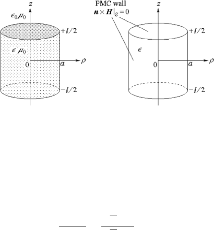
Figure 6.27: Dielectric resonator (left) and perfect-magnetic-conductor wall
approach (right).
causes total internal reflections resulting in the confinement of energy in the
dielectric object. The reflection coefficient of a plane wave normally incident
at the dielectric to air boundary is given by
Γ =
η
0
− η
η
0
+ η
=
√
²
r
− 1
√
²
r
+ 1
²
r
À1
≈ +1,
where η
0
and η denote the wave impedance of the air and the dielectric, re-
spectively. Hence the dielectric to air boundary can be approximated by a
hypothetical perfect magnetic conductor (PMC) surface, on which the tan-
gential components of the magnetic field is required to vanish, i.e., an open-
circuit surface. Note that, the air to dielectric boundary, on the contrary,
can be approximated by a perfect electric conductor (PEC) surface, i.e., a
short-circuit surface.
Although the PMC wall model may not lead to the exact solution, it gives
a first-order approximation to the problem and supplies reasonable results.
We choose the circular cylindrical dielectric resonator as an example, as
shown in Fig. 6.27. The permittivity of the material is large enough and the
permeability is µ
0
.
(1) TE Modes, U = 0
Dielectric cylinder including the axis at the center, the coefficient of the
Neumann function must be zero. The angular dependence of the field function
may either be even symmetrical or odd symmetrical, here we choose the even
symmetrical functions. The function V are given as follows
V = AJ
n
(T ρ) cos nφ cos(βz + θ), (6.334)
The relation between β and T is given by
β
2
+ T
2
= k
2
= ω
2
µ
0
². (6.335)
6.8 Dielectric Resonators 389
According to the PMC wall model, the boundary conditions on the side
surface of the cylinder, ρ = a, are
H
z
(a) = T
2
V (a) = 0
H
φ
(a) =
1
ρ
∂
2
V
∂φ ∂z
¯
¯
¯
¯
a
= 0
→ J
n
(T a) = 0, T
c
=
x
nm
a
, (6.336)
where x
nm
is the mth root of the Bessel function of the nth order. Similarly,
the boundary conditions on the end surfaces, z = ±l/2, are
H
φ
(−l/2) =
1
ρ
∂
2
V
∂φ ∂z
¯
¯
¯
¯
−l/2
= 0
H
ρ
(−l/2) =
∂
2
V
∂ρ ∂z
¯
¯
¯
¯
−l/2
= 0
→ sin(−βl/2+θ) = −sin(βl/2−θ) = 0,
H
φ
(l/2) =
1
ρ
∂
2
V
∂φ ∂z
¯
¯
¯
¯
l/2
= 0
H
ρ
(l/2) =
∂
2
V
∂ρ ∂z
¯
¯
¯
¯
l/2
= 0
→ sin(βl/2 + θ) = 0,
which are easily put in the form
sin(βl/2) cos θ − cos(βl/2) sin θ = 0, (6.337)
and
sin(βl/2) cos θ + cos(βl/2) sin θ = 0. (6.338)
From these it follows that
sin(βl/2) cos θ = 0, cos(βl/2) sin θ = 0. (6.339)
There are two ways to satisfy the above two equations simultaneously:
1.
θ = 0, sin(βl/2) = 0, β = pπ/l, p = 0, 2, 4, ···, for even modes.
2. θ = π/2, cos(βl/2) = 0, β = pπ/l, p = 1 , 3, 5, ···, for odd modes.
Finally we have the natural angular frequency of the TE
nmp
mode
ω
TE
nmp
=
1
√
µ
0
²
r
³
pπ
l
´
2
+
³
x
nm
a
´
2
. (6.340)
The lowest TE mode is the TE
010
mode, where n = 0, m = 1, p = 0, β = 0
and the natural frequency is
ω
TE
010
=
1
√
µ
0
²
x
01
a
=
2.405
a
√
µ
0
²
. (6.341)
The field components of TE
010
mode are as follows
E
φ
= −jωµ
0
T AJ
1
(T ρ), H
z
= T
2
AJ
0
(T ρ). (6.342)
390 6. Dielectric Waveguides and Resonators
(2) TM Modes, V = 0
The function U and the field components are written in the form
U =AJ
n
(T ρ) cos nφ cos(βz + θ), (6.343)
The relation between β and T is also given by (6.335)
The boundary condition on the side surface of the cylinder, ρ = a, is
H
φ
(a) =
jω²
ρ
∂U
∂φ
¯
¯
¯
¯
a
= 0 → J
0
n
(T a) = 0, T
c
=
y
nm
a
, (6.344)
where y
nm
is the mth root of the derivative of the Bessel function of the nth
order. The boundary conditions on the end surfaces, z = ±l/2, are
H
φ
(−l/2) = −jω²
∂U
∂ρ
¯
¯
¯
−l/2
= 0
H
ρ
(−l/2) =
jω²
ρ
∂U
∂φ
¯
¯
¯
−l/2
= 0
→ cos(βl/2 − θ) = 0,
H
φ
(l/2) = −jω²
∂U
∂ρ
¯
¯
¯
l/2
= 0
H
ρ
(l/2) =
jω²
ρ
∂U
∂φ
¯
¯
¯
l/2
= 0
→ cos(βl/2 + θ) = 0,
which give
β = pπ/l,
½
p=0, 2, 4, ···, for even modes,
p=1, 3, 5, ···, for odd modes,
Finally we have the natural angular frequency of TM
nmp
mode
ω
TM
nmp
=
1
√
µ
0
²
r
³
pπ
l
´
2
+
³
y
nm
a
´
2
. (6.345)
The lowest TM mode is the TM
111
mode, which is not a circumferential
symmetrical mode, where n = 1, m = 1, p = 1 and the natural frequency is
ω
TM
111
=
1
√
µ
0
²
r
³
π
l
´
2
+
³
y
11
a
´
2
=
1
√
µ
0
²
s
³
π
l
´
2
+
µ
1.841
a
2
. (6.346)
When the resonator has a small length-radius ratio, the TE
010
mode is the
dominant mode, whereas for the resonator with a large length:radius ratio,
the TM
111
mode is the dominant mode.
A comparison of the resonant frequencies and field components of the di-
electric resonator modeled by a PMC wall with those of the metallic resonator
modeled by a PEC wall shows that the TE modes in one type of resonator
are the dual modes of the TM modes in the other, and vice versa. The two
types of boundary conditions, a PMC or open-circuit surface and a PEC or
short-circuit surface, are dual boundary conditions.