Graef M. Introduction to conventional transmission electron microscopy
Подождите немного. Документ загружается.

188 The transmission electron microscope
High
Tension
+
-
V
F
Grid or
Wehnelt
Anode
Electrical
Ground
I
F
R
W
R
0
<0
>0
Gun
Crossover
(a)
(b)
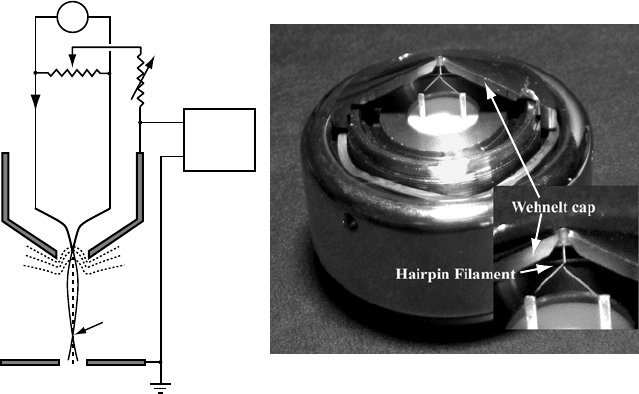
Fig. 3.23. (a) Schematic
of a thermionic electron gun; (b) photograph of the cross-sectioned
Wehnelt assembly of the JEOL 120CX microscope.
filaments, with a work function of W = 4.5 eV, are operated at 2600–2800 K.
Single-crystal LaB
6
emitters have a work function of 2.7 eV, and are operated in
the range 1700–1900 K.
The anode surface is kept at ground potential, and the high-tension supply gen-
erates a voltage (the acceleration voltage E) between the filament tip and the anode
plate. The filament is kept at a negative potential of −E V with respect to the anode,
so that electrons emitted from the tip are accelerated towards the anode. Thermal
emission occurs not only from the tip but also from the flanks of the tip, and this
would lead to electrons traveling at large angles with respect to the optical axis. To
prevent emission from the filament flanks, a conical surface is introduced around
the filament. This surface is known as the grid or, more commonly, the Wehnelt
cap. The grid is kept at a small negative voltage with respect to the tip by means
of a variable resistor R
W
. On the microscope console the resistance R
W
can be
changed by means of the gun bias control. The bias resistor is tied into the filament
heating circuit, so that the energy of the accelerated electron will always be E eV,
regardless of the bias setting.
The negative Wehnelt cap produces a zero-potential contour, indicated with dot-
ted lines in Fig. 3.23(a). The bias voltage is set so that this contour intersects the
filament close to the tip. Regions along the flanks of the filament experience a neg-
ative potential and hence thermionic emission will be suppressed. Changing the
gun bias amounts to changing the location of this zero-potential surface, and hence
3.7 Basic electron optics: electron guns 189
the size of the emitting region. If the bias voltage is too large then there will be
no intersection between the zero-potential contour and the tip, which means that
there will be no emission. If the bias voltage is too low, then the size of the emitting
region will be large, and therefore the gun brightness will decrease. There is an op-
timal gun bias setting for which the brightness is maximized. This voltage setting
depends sensitively on the precise location of the tip within the Wehnelt cap and
on the shape of the Wehnelt cap. Typical filament currents at maximum brightness
are about 100
µA for tungsten filaments and this is indicated by the beam current
on the microscope console.
3.7.3.2 Schottky and field emission electron guns
Schottky and field emission electron guns are quite similar in construction, so we
will describe them both in this section. A Schottky electron gun employs a tungsten
single-crystal filament with a flat circular (100) facet normal to the optical axis;
the diameter of this facet is typically around 1
µm. The filament is coated with
a thin ZrO layer, which reduces the work function from 4.5 to about 2.8 eV. The
operating temperature can hence also be lowered to about 1800 K. A suppressor cap
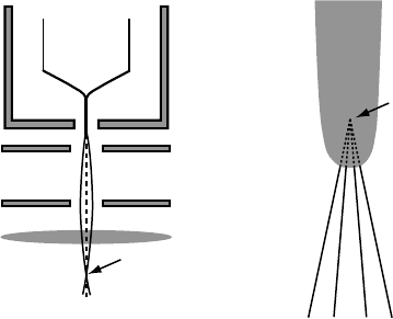
(see Fig. 3.24a) surrounds the filament so that only the very tip protrudes through
the cap. The suppressor cap takes on the role of the Wehnelt cap in a thermionic
gun: a voltage of −2 kV prevents electron emission from the flanks of the filament
crystal.
An extractor plate, kept at a positive potential in the range 2–7 kV, provides
the electric field needed to extract electrons from the tip. The field is inversely
proportional to the tip radius so that fields of several volts per nanometer can be
obtained. The electrons are then accelerated by the anode plate and emerge through
a small hole along the optical axis. The electrons appear to emanate from a point
F
Suppressor
Anode
Extractor
Gun lens
Gun
Crossover
Virtual
Source
Filament
Tip
(a)
(b)
Fig. 3.24. Schematic illustration of a Schottky electron gun.

190 The transmission electron microscope
inside the filament (Fig. 3.24b), the virtual source with a size of about 10 nm, and
do not form a gun cross-over, so that a gun lens is needed to intersect the electron
trajectories with the optical axis. The gun lens is an electrostatic lens with a variable
potential in the range 0.5–2 kV. A strongly excited gun lens will bring the gun cross-
over close to the gun, whereas a weakly excited gun lens will have a lower cross-over
(closer to the first condensor lens). The emission current is typically about 150
µA.
A cold field emission gun is very similar in construction to the Schottky gun. It
has the same components: suppressor, extractor, anode, and gun lens. The filament
tip (typically tungsten) has a radius of about 100 nm and the extractor voltage
provides a field strength sufficient to cause electrons near the Fermi level to tunnel
through the barrier potential (which is narrow because of the applied field). The
gun vacuum for a cold field emitter must be around 10
−8
Pa, whereas a Schottky
emitter requires about 10
−6
Pa. The Schottky emitter also provides a more stable
emission current over a long period of time. Cold field emitter tips must be flashed
regularly, to remove contaminants from the emitter surface. Parameter ranges for
both Schottky and cold field emission guns can be found in Table 3.2.
3.7.4 Beam energy spread and chromatic aberration
Electrons which leave a thermionic emission tip have initial energies of at least the
work function W . In this energy range the Fermi–Dirac distribution function (3.46)
reduces to a Maxwell–Boltzmann distribution (taking the zero of the energy scale
at the Fermi level):
f (E, T ) =
1
1 + e
−E /k
B
T
≈ e
−E /k
B
T
. (3.59)
We can then use equation (3.51) to define the normalized energy distribution g(E)
[HK89b]:
g(E)dE ≡
d j
z
j
z
=
E
(k
B
T )
2
f (E, T )dE. (3.60)
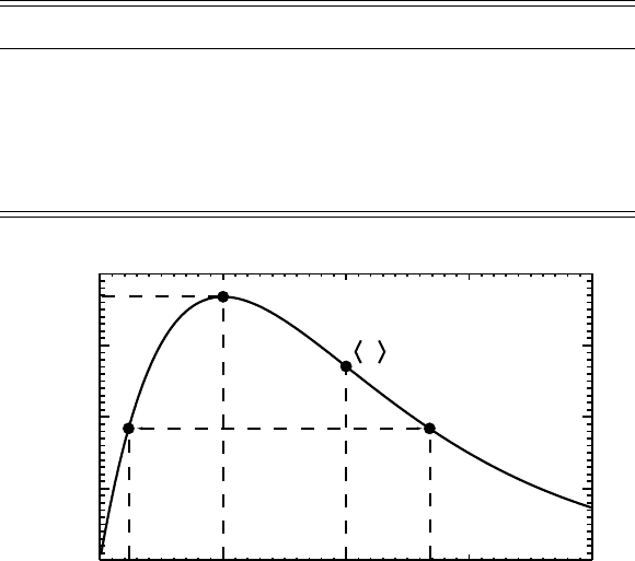
The distribution k
B
Tg(E) is shown in Fig. 3.25 as a function of the variable E/k
B
T .
The mean electron energy is given by E=2k
B
T , the most probable energy
corresponds to the maximum of the curve at E
m
= k
B
T , and the energy spread
(full width at half maximum, or FWHM) is given by E = 2.446k
B
T . Table 3.3
shows the relevant energies for a tungsten emitter and a LaB
6
emitter, using a typical
operating temperature. The last column shows the corresponding expressions for
a thermal field emission gun. The energy spread for field emission is in the range
0.2–0.4 eV. The energy distribution should be superimposed on the final energy of
the electrons after acceleration.
3.7 Basic electron optics: electron guns 191
Table 3.3. Energy distribution parameters for a tungsten emitter
and a LaB
6
emitter; energies in eV, temperature in K. The last
column shows the explicit expressions for a thermal field
emitter [HK89b].
W LaB
6
Thermal field emission
Work function 4.5 2.7
Temperature 2800 1900
f (W, T )7.95 × 10
−9
6.89 × 10
−8
E 0.482 0.327 π pd cot(π pd)
E
m
0.241 0.164 dπ p/ sin(π p)
E 0.590 0.400 k
B
T [ln p − ln(1 − p)]
0.4
0.3
0.2
0.1
0.0
01234
k
B
Tg(E)
E/k
B
T
E
m
E
∆E
Fig. 3.25. Normalized energy distribution k
B
Tg(E) as a function of E/ k
B
T for thermionic
emission. The mean energy, most probable energy, and energy spread are indicated.
It was discovered experimentally by Boersch in 1954 [Boe54] that there is an
anomalous broadening of the energy distribution for thermionic emission, that the
energy distribution tends to become symmetric around its maximum E
m
(which
is not the case for the Maxwell–Boltzmann distribution shown in Fig. 3.25), and
that the mean energy E is shifted. These effects increase with increasing beam
current. Although there is at present no single theory explaining all of these effects,
it has been shown that they are due to stochastic Coulomb interactions between the
electrons, whenever they come close together (as in a cross-over). This has led to
modifications of the shape of the Wehnelt cap; the net result of these modifications is
that the cross-over moves further away from the cathode (telescopic effect) and can
sometimes be completely avoided. The Boersch effect occurs whenever electrons
are forced into a narrow beam, e.g. in electron lithography where high probe currents

192 The transmission electron microscope
and small probe diameters are required. The energy spread of a thermionic gun is
increased to about 1 eV by the Boersch effect.
Recent developments in electron optical design of monochromators make it pos-
sible to reduce the energy spread of the beam down to the range 50–200 meV. Such
energy filters are becoming available on dedicated microscopes and may revolu-
tionize the study of electron energy loss mechanisms.
Chromatic aberration is caused by the fact that the focal length of a lens depends
on the wavelength and hence on the electron energy. Small fluctuations in the high-
voltage supply or in the lens power supply will cause small variations in λ (and thus
in
ˆ
) and in B(z), respectively. There are four important sources of fluctuations
and/or energy changes in a microscope:
(i) intrinsic energy spread of the electrons leaving the filament, typically E/E ≈ 10
−5
(see Tables 3.1 and 3.2);
(ii) high-voltage instabilities, V / V ≈ 10
−6
min
−1
;
(iii) fluctuations I /I of the lens currents;
(iv) energy losses in the specimen.
As a consequence of these fluctuations the focal length f of a magnetic lens will
no longer be precisely defined and instead we can talk about the defocus spread
[Spe88]:
= C
c
σ
2
(V )
V
2
+
4σ
2
(I )
I
2
+
σ
2
(E)
E
2
1/2
, (3.61)
where σ indicates the standard deviation. The first term represents fluctuations of
the acceleration voltage, the second represents fluctuations of the focal length due
to fluctuations of the lens current I (recall that the focal length depends on the
square of the field B(z), hence the factor of 4 above), and the last term corresponds
to the intrinsic energy spread of the electron gun, including the Boersch effect. The
chromatic aberration coefficient C
c
, typically expressed in mm, can be written in
terms of the axial field distribution B(z) as [HK89a]:
C
c
=
e
8m
ˆ
.
z
1
z
0
B
2
(z)h
2
(z)dz, (3.62)
where h(z) is a paraxial trajectory that leaves an axial object point with unit slope.
The net effect of chromatic aberration is that the image of a point will be blurred
into a disk. Chromatic aberration can be removed in principle by combining the lens
with an electrostatic mirror with negative C
c
. We will return to chromatic aberration
in Chapter 10.
3.7 Basic electron optics: electron guns 193
3.7.5 Beam coherence
The primary purpose of the electron gun and the illumination system as a whole is
to create a stream of electrons with a well-known reference state. We will see in
Chapter 5 that the equations describing the interaction between beam electrons and
the sample can be solved when the incident electron can be represented by a plane
wave. We must, therefore, introduce a measure for how well a beam electron can
be described by a plane wave.
The Heisenberg uncertainty principle states that the product of the uncertainty or
spread in energy and the uncertainty in time must be larger than Planck’s constant, or
Et > h. (3.63)
For a thermionic gun with an energy spread E of 1 eV we find that t ≈ 4 ×
10
−15
s. During this time interval the electron travels a distance λ
tc
, known as the
temporal coherence length, given by
λ
tc
= ct
/
1 −
1
γ
2
. (3.64)
At 200 kV, we have λ
tc
= 861 nm. The temporal coherence length of optical lasers
varies from a few centimeters to many meters. The temporal coherence length
would be infinite for an electron gun with zero energy spread, i.e. a perfectly
monochromatic electron gun. The longer the temporal coherence length, the more
“identical” the beam electrons are.
Ideally, all beam electrons would emanate from a single point on the filament. In
reality, the electrons that reach the sample appear to leave a point which coincides
with the gun cross-over for the thermionic gun and the virtual source for the field
emission gun. This virtual source has a finite lateral extent (lateral means normal
to the optical axis) of a few nanometers for field emission guns to 10–50
µm for
thermionic guns. We will see in Section 3.8 that in most cases the electron beam
passes through an aperture (the second condensor aperture) before reaching the
sample. The beam divergence angle θ
c
subtended by this aperture at the sample can
be used to define the transverse coherence width or spatial coherence width λ
sc
of
the illumination:
λ
sc
=
λ
2πθ
c
. (3.65)
If two object points A and B are separated from each other by a distance r <λ
sc
,
then the amplitudes of the waves scattered by these two points must be added before

194 The transmission electron microscope
converting to intensities:
I =|
A
+
B
|
2
; (3.66)
=|ψ
A
|
2
+|ψ
B
|
2
+
A
∗
B
+
∗
A
B
; (3.67)
= I
A
+ I
B
+ I
AB
(coherent). (3.68)
If the separation between the two object points is much larger than the coherence
width, then the final scattered intensity is given by
I = I
A
+ I
B
=|ψ
A
|
2
+|ψ
B
|
2
(incoherent). (3.69)
The difference between the coherent and incoherent cases is the interference term
I
AB
. The intermediate range, i.e. distances comparable to the coherence width, is
described by the theory of partial coherence.
Under normal observation conditions with a thermionic electron gun, the illumi-
nating aperture is incoherently filled with statistically independent electron sources.
For field emission systems the entire illuminating aperture is coherently filled and
the transverse coherence width at the aperture plane [SZ92] is defined by
λ
sc,a
=
λ
2πθ
s
, (3.70)
where θ
s
is the angle subtended by the source at the aperture plane. A smaller
aperture radius will increase the transverse coherence width, as will a decrease of
the acceleration voltage.
It is intuitively clear that an infinitely small aperture will only allow one single
wave vector to contribute to the incident electron beam, hence a pure plane wave is
obtained. Experimentally this cannot be established without severe losses in current
density. For high-resolution observations, where interference between the different
diffracted beams is employed to obtain structural images, the coherence width is
important and an appropriate choice of the condensor aperture radius must be made
by the microscope operator. A smaller aperture will increase the coherence width but
at the same time the current density will be reduced, thus requiring longer exposure
times. Image contrast caused by interference from beams emanating from regions
of the sample within the coherence width is called phase contrast. In Chapter 10
we will deal extensively with various types of phase contrast.
For in-depth discussions of coherence in optical and electron optical systems
we refer the reader to [Goo68, Chapter 6], [Spe88, Chapter 4], [SZ92, Chapter 8],
and [BW75, Section 7.5.8].

3.8 The illumination stage: prespecimen lenses 195
3.7.6 How many electrons are there in the microscope column?
It is a simple exercise to calculate how many beam electrons are present in the
microscope column at any given moment in time. A beam current I of 1 nA cor-
responds to 6.25 × 10
18
electrons C
−1
× 10
−9
Cs
−1
,or6.25 × 10
9
electrons s
−1
.
Electrons accelerated by a potential of E volts travel at a velocity v = βc, and in
one second travel a distance of = v m. If electrons are emitted from the gun at
regular intervals in time (a reasonable approximation), then we can compute the
linear electron density n
e
per nA of beam current in the column:
n
e
=
6.25 × 10
9
v
.
At E = 200 kV, electrons travel at a velocity of v = 0.695c, which results in a linear
electron density of about 30 electrons m
−1
nA
−1
. The average distance between
consecutive electrons is then about 3 cm, which is much larger than the thickness of
the sample. As far as the sample is concerned, it is thus a very good approximation
to consider each beam electron separately, and this is precisely what the equations
derived in Chapter 2 accomplish.
This illustrates once again that an electron diffraction experiment is, in fact,
the quintessential quantum mechanics experiment; individual electrons are sent
through a sample with a very large number of “slits”, and since we do not attempt
to determine precisely which “slit” the electron traveled through, an interference
pattern will result at the detector.
It takes an electron a time t = z
0
/v to traverse a sample of thickness z
0
; for
a 100 nm thick sample, and a 200 kV electron, t = 4.8 × 10
−16
s. This time
interval is about four orders of magnitude shorter than the typical duration of a
single cycle of a lattice vibration, and therefore it is a very good approximation
to consider the atoms to be stationary throughout the interaction with the beam
electron. The time interval between two consecutive electrons is 1.6 × 10
−10
s for
a 1 nA beam of 200 kV electrons; during this time interval atoms have gone through
about 100 vibration periods, which means that there is no correlation between the
position of an atom for one beam electron and its position for the next beam electron.
This justifies the approximations made in the derivation of the Debye–Waller factor
in Chapter 2.
3.8 The illumination stage: prespecimen lenses
The reader might be tempted to ask the question: why are there so many lenses
in an electron microscope? This is a relevant question, and when we compare the
early microscopes with the computer-controlled machines currently on the market
we cannot avoid noticing that the current number of lenses and correction coils is
196 The transmission electron microscope
far greater than that of the older machines. The easiest way to understand why there
are so many lenses is to analyze what each lens does in relation to its neighbors.
It is instructive to start with a microscope without lenses and to add lenses, one
at a time. We will divide the microscope column into prespecimen, specimen, and
post-specimen regions, and describe the functionality of the main lenses in each of
those regions. While the actual number of lenses for any particular microscope may
vary, we will focus in the next sections on those lenses that are present in nearly
every recent microscope model.
The illumination system of a TEM serves one important purpose: to create a beam
of electrons in a well-defined reference state (either a plane wave or a converged
fine probe). Only if we know what the reference state is can we hope to extract
information concerning the sample by analyzing the modified signal R
(recall the
discussion on page 106). It is thus important for the microscope operator to under-
stand the purpose of each of the lenses in the illumination system. This situation is
somewhat similar to that encountered when one tries to solve a differential equation:
the equation can only be completely solved if the initial conditions are specified,
and solutions may depend in a rather sensitive way on those initial conditions. We
have already seen that, in the case of the TEM, the relevant differential equation is
the stationary Schr¨odinger equation. If we wish to compare theoretical solutions to
this equation with experimental observations, we must from the beginning ensure
that both have the same initial conditions. The illumination system is, hence, of cru-
cial importance for the interpretation of experimental images based on a theoretical
description of the image formation mechanism.
Let us consider the configuration shown in Fig. 3.26(a): an electron gun directly
illuminates a specimen, without any magnetic lenses present. This configuration
offers only limited control over the electron beam: the Wehnelt voltage or gun bias
combined with the geometry of the entire assembly determine the location and size
of the cross-over. The total number of electrons that reach any specific area on the
specimen is rather small and can be changed somewhat by adjusting the gun bias.
Since this changes the area on the filament from which electrons are emitted, the
beam brightness would also change. This is clearly an undesirable configuration
since we would like to be able to form a very fine probe on the sample surface or use
a parallel incident beam. So we decide to add a single magnetic lens, the condensor
lens C
1
, positioned close to the anode, as shown in Fig. 3.26(b).
If this lens C
1
is excited such that the image of the gun cross-over (with a
diameter of s = 10–100
µm) is formed on the specimen surface, then the size of
the smallest illuminated area (the spot size) equals sv/u, generally of the same order
of magnitude as the cross-over diameter itself. This is again undesirable because
we may wish to investigate details on a length scale of nanometers, not microns,
and this will require nanometer-sized probes.
3.8 The illumination stage: prespecimen lenses 197
S
A
W
F
Gun cross-over
diameters
(a)
S
A
W
F
u
v
C
1
C
1
a
Smallest spot
diameter = s
v
u
(b)
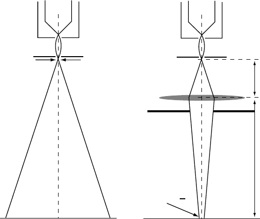
Fig. 3.26. (a) Prespecimen ray diagram without lenses. The gun cross-over diameter s is
10–100 µm. (b) Ray diagram with a single condensor lens C
1
. The image of the gun cross-
over is magnified by a factor v/u. The fixed aperture C
a
1
limits the angular range of electron
trajectories.
Most microscopes have a fixed aperture, the first condensor aperture C
a
1
, located
just below the lens C
1
. The purpose of this aperture is to capture electrons which
travel at large angles with respect to the optical axis and to prevent them from
hitting the inner surfaces of the subsequent lens pole pieces. This cuts down on the
number of x-rays that are generated in the column.
If we want the spot size on the specimen to be much smaller than the diameter
of the cross-over, then we must make v much smaller than u; this can be done
by strongly exciting the lens C
1
, as is shown in the ray diagram of Fig 3.27(a).
The stronger the excitation, the shorter the focal length will be and the smaller the
magnification factor v/u (which is then known as a demagnification factor). When
v is much smaller that u, as indicated in Fig. 3.27(a), most electrons will travel
at rather large angles with respect to the optical axis, even after passing through
C
a
1
, and we obviously need another lens to focus the beam into a small area on
the specimen. This second lens is known as C
2
(condensor 2) and it has a variable
current control and hence variable focal length.
The second condensor lens has the C
1
cross-over as its object plane, and by
varying the C
2
current we can position the conjugate image on any plane above, at,
or below the sample. If the C
2
lens current is such that the focal length is longer
than the distance from the lens center to the sample, then the lens is said to be