Masters G.M. Renewable and Efficient Electric Power Systems
Подождите немного. Документ загружается.

118 THE ELECTRIC POWER INDUSTRY
pass through turbine blades, causing a shaft to spin. The function of the generator,
then, is to convert the rotational energy of the turbine shaft into electricity.
3.3.1 A Simple Generator
Electric generators are all based on the fundamental concepts of electromagnetic
induction developed by Michael Faraday in 1831. Faraday discovered that moving
a conductor through a magnetic field induces an electromagnetic force (emf), or
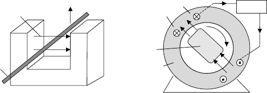
voltage, across the wire, as suggested in Fig. 3.9a. A generator, very simply,
is an arrangement of components designed to cause relative motion between a
magnetic field and the conductors in which the emf is to be induced. Those
conductors, out of which flows electric power, form what is called the armature.
Most large generators have the armature windings fixed in the stationary portion
of the machine (called the stator), and the necessary relative motion is caused
by rotating the magnetic field, as shown in Fig. 3.9b.
To help illustrate generation of ac, consider the simple generator shown in
Fig. 3.10. The rotor in this case is just a 2-pole magnet (1 north pole and 1
south pole), which for now we can consider to be just an ordinary permanent
magnet. The stator consists of iron, shaped somewhat like a C (backwards, in
this case), with some copper wire (the armature) wrapped around the iron. The
purpose of the iron in the stator is to provide a low reluctance path for the
magnetic flux lines, channeling as much flux as possible through the copper
armature windings. You may recall from Chapter 1 that the low reluctance of
ferromagnetic materials (e.g., iron) causes flux to prefer to stay in the iron,
which is exactly analogous to current-carrying electrons wanting to stay in copper
wires. And just as low-resistance copper wire allows more current to flow, low
reluctance ferromagnetic materials allow more magnetic flux (flux doesn’t “flow,”
however).
As the rotor turns, magnetic flux passes through the stator and the arma-
ture windings, in one direction, then diminishes to zero, then increases in the
+
−
Voltage
Motion
Magnetic
field
Conductor
NS
N
S
i
Armature
conductors
Rotor
(a) (b)
Stator
Load
Figure 3.9 Voltage and current can be created by (a) moving a conductor through a
magnetic field, or (b) moving the magnetic field past the conductors. The armature wind-
ings indicate current flow into the page with an “x” and current out of the page with a
dot (the x is meant to resemble the feathers of an arrow moving away from you; the dot
is the point of the arrow coming toward you).

POLYPHASE SYNCHRONOUS GENERATORS 119
N
S
Flux
lines
f
N
S
NS
e
=
N
d
f
dt
Stator
Rotor
N
S
Figure 3.10 As the permanent-magnet rotor turns, it causes magnetic flux within the
iron stator to vary (approximately) sinusoidally. The windings around the stator therefore
see a time-varying flux, which creates a voltage across their terminals.
f
e
=
N
d
f
dt
(a)
(b)
Figure 3.11 Changing flux in the stator creates an emf voltage across the windings.
other direction. Ideally, the flux φ would vary sinusoidally as suggested in
Fig. 3.11a. From Faraday’s law, whenever a winding links a time-varying amount
of magnetic flux φ, there will be a voltage e (electromotive force) created across
the winding:
e = N
dφ
dt
(3.1)
3.3.2 Single-Phase Synchronous Generators
Suppose we want to generate voltage at a frequency of 60 Hz so that it will
match the frequency of conventional (U.S.) power. How fast would the rotor of
the simple generator in Fig. 3.10 have to turn? Each revolution of the rotor gives
one voltage cycle, so
N
s
= shaft rotation rate =
1 revolution
cycle
×
60 cycles
sec
×
60 sec
min
= 3600 rpm
(3.2)
120 THE ELECTRIC POWER INDUSTRY
To generate 60 Hz using this 2-pole generator would therefore require that the
rotor turn at a fixed rate of exactly 3600 rpm. Such a fixed-speed machine is
called a synchronous generator since it is synchronized with the utility grid.
Most conventional electric power is generated using synchronous generators (this
is not the case for wind turbines, however).
While we could imagine the magnetic field in the rotor of a generator to be
created using a permanent magnet, as suggested in Fig. 3.10, that would greatly
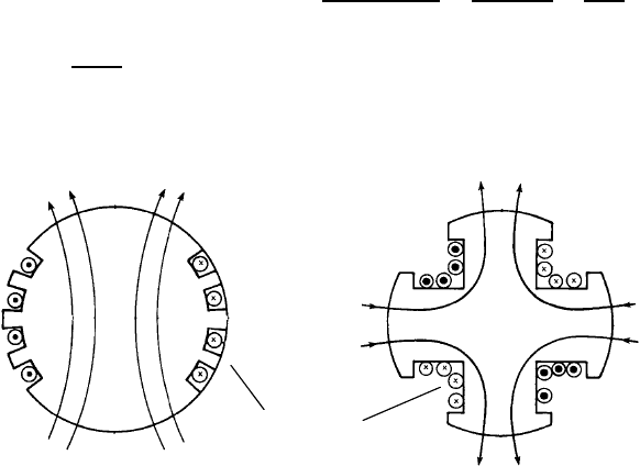
limit the amount of power that could be generated. Instead, the magnetic field is
created by sending dc through brushes and slip rings into conductors affixed to
the rotor. Field windings may be imbedded into slots that run along the rotor as
shown in Fig. 3.12a, or they may be wound around what are called salient poles,
as shown in Fig. 3.12b. Salient pole rotors are less expensive to fabricate and
are often used in slower-spinning hydroelectric generators. High-speed turbines
and generators use round rotors, which are better able to handle the centrifugal
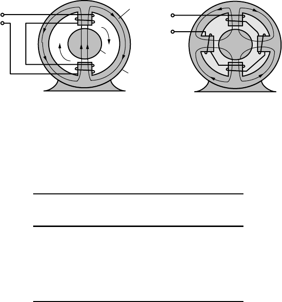
forces and resulting stresses. Figure 3.13a shows a complete 2-pole generator
with a round rotor, while Fig. 3.13b is a 4-pole generator with a salient rotor.
Notice the 4-pole generator has four poles in both the rotor and stator.
Adding more poles allows the generator to spin more slowly while still pro-
ducing a desired frequency for its output power. For example, when the rotor in
a 4-pole machine makes one revolution, it generates two cycles on the output
lines. This means that it only needs to rotate half as fast as the 2-pole machine,
namely 1800 rpm, in order to generate 60-Hz ac. In general, rotor speed N
s
as a
function of number of poles p and output frequency required f is given by
N
s
= shaft rotation rate (rpm) =
1 revolution
(p/2) cycles
×
f cycles
s
×
60 s
min
(3.3)
N
s
=
120f
p
(3.4)
N
N
N
S
S
S
Magnetic flux
Field windings
Magnetic flux
(a) (b)
Figure 3.12 Field windings on (a) 2-pole, round rotor and (b) 4-pole, salient rotor.
CARNOT EFFICIENCY FOR HEAT ENGINES 121
(a) (b)
N
S
Flux
Output
Rotor
Stator
Output
N
S
N
S
Figure 3.13 (a) A 2-pole machine has one N and one S pole on the rotor and on the
stator. (b) A 4-pole machine has 4 poles on the rotor and 4 on the stator.
TA BLE 3.2 Shaft Rotation (rpm) as a Function of
Desired Output Frequency and Number of Poles
Poles
p 50 Hz rpm 60 Hz rpm
2 3000 3600
4 1500 1800
6 1000 1200
8 750 900
10 600 720
12 500 600
While the United States uses 60 Hz exclusively for power, Europe and parts
of Japan use 50 Hz. Table 3.2 provides a convenient summary of rotor speeds
required for a synchronous generator to deliver power at 50 Hz and at 60 Hz.
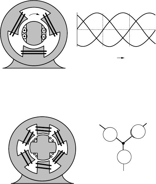
3.3.3 Three-Phase Synchronous Generators
The machines shown thus far have been single-phase generators. In Chapter 2,
we saw the value of 3-phase power, especially when large amounts of power are
needed. To provide 3-phase power, we can keep the simple rotor with a single
pair of north and south poles, but we need to add another winding to the stator
as has been done in Fig. 3.14. Now during each revolution of the shaft, the rotor
sweeps by each of the three stator windings, thereby inducing a voltage in each
stator that is 120
◦
out of phase with the adjacent windings.
Figure 3.15 shows a 4-pole, 3-phase generator with a salient-pole rotor, which
means it spins at only half the rotor speed compared to a 2-pole machine.
122 THE ELECTRIC POWER INDUSTRY
N
S
Φ
A
Φ
C
wt
Φ
B
0
(a) (b)
2p/3 2p4p/3
V
A
V
B
V
C
Figure 3.14 (a) A 2-pole, 3-phase synchronous generator. (b) Three-phase stator output
voltage.
Φ
A
Φ
B
Φ
B′
Φ
A′
Φ
C′
Φ
C
A
A′
B
B′
C′
C
V
A
V
B
V
C
N
N
S
S
Figure 3.15 A 4-pole, 3-phase, wye-connected, synchronous generator with a 4-pole
rotor. The dc rotor current needs to be delivered to the rotor through brushes and slip rings.
3.4 CARNOT EFFICIENCY FOR HEAT ENGINES
Over 90% of U.S. electricity is generated in power plants that convert heat into
mechanical work. The heat may be the result of nuclear reactions, fossil-fuel
combustion, or even concentrated sunlight focused onto a boiler. Almost all of
this 90% is based on a heat source boiling water to make steam that spins a turbine
and generator, but there is a rapidly growing fraction that is generated using gas
turbines. The best new fossil-fuel power plants use a combination of both steam
turbines and gas turbines to generate electricity with very high efficiency.
Steam engines, gas turbines, and internal-combustion engines are examples
of machines that convert heat into useful work. What we are interested in here
is, How efficiently can they do so? This same question will be asked when we
describe fuel cells, photovoltaics, and wind turbines in future chapters, and in each
case we will encounter quite interesting, fundamental limits to their maximum
possible energy-conversion efficiencies.
CARNOT EFFICIENCY FOR HEAT ENGINES 123
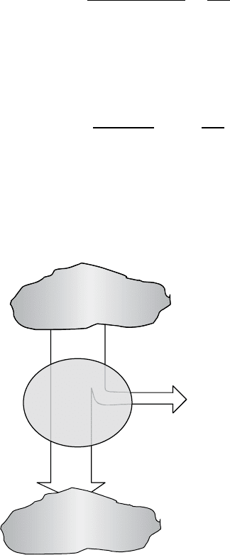
3.4.1 Heat Engines
Very simply, a heat engine extracts heat Q
H
from a high-temperature source,
such as a boiler, converts part of that heat into work W , usually in the form of
a rotating shaft, and rejects the remaining heat Q
C
into a low-temperature sink
such as the atmosphere or a local body of water. Figure 3.16 provides a general
model describing such engines.
The thermal efficiency of a heat engine is the ratio of work done to input
energy provided by the high-temperature source:
Thermal efficiency =
Net work output
Total heat input
=
W
Q
H
(3.5)
Since energy is conserved,
Q
H
= W + Q
C
(3.6)
which leads to another expression for efficiency:
Thermal efficiency =
Q
H
− Q
C
Q
H
= 1 −
Q
C
Q
H
(3.7)
3.4.2 Entropy and the Carnot Heat Engine
The most efficient heat engine that could possibly operate between a hot and cold
thermal reservoir was first described back in the 1820s by the French engineer
Sadi Carnot. To sketch out the basis for his famous equation, which links the
Q
H
W
Q
C
High-temperature
SOURCE,
T
H
Low-temperature
SINK,
T
C
HEAT
ENGINE
Figure 3.16 A heat engine converts some of the heat extracted from a high-temperature
reservoir into work, rejecting the rest into a low-temperature sink.

124 THE ELECTRIC POWER INDUSTRY
maximum possible efficiency of a heat engine to the temperatures of the hot and
cold reservoirs, we need to introduce the concept of entropy.
As is often the case in thermodynamics, the definition of this extremely impor-
tant quantity is not very intuitive. It can be described as a measure of molecular
disorder, or molecular randomness. At one end of the entropy scale is a pure
crystalline substance at absolute zero temperature. Since every atom is locked
into a predictable place, in perfect order, its entropy is defined to be zero. In
general, substances in the solid phase have more ordered molecules and hence
lower entropy than liquid or gaseous substances. When we burn some coal,
there is more entropy in the gaseous end products than in the solid lumps we
burned. That is, unlike energy, entropy is not conserved in a process. In fact,
for every real process that occurs, disorder increases and the total entropy of the
universe increases.
The concept of ever-increasing entropy is enormously important. It tells us
that in any isolated system (e.g., the universe) in which the total energy cannot
change, the only processes that can occur spontaneously are ones that result in an
increase in the entropy of the system. One implication is that heat flows naturally
from warm objects to cold ones, and not the other way around. It also dictates the
direction of certain chemical reactions, as we’ll see in Chapter 4 where entropy
will be used to determine the maximum possible efficiency of fuel cells.
When we started the analysis of the heat engine in Fig. 3.16, we began by
tabulating energy flows. The first law of thermodynamics treats energy in the
form of heat transfer on an equal basis with energy that shows up as work done
by the engine. For an entropy analysis, that is not the case. Work is considered to
be an idealized process in which no increase in disorder occurs, and hence it has
no accompanying entropy transfer. This is a key distinction. Processes involve
heat transfer and work. Heat transfer is accompanied by entropy transfer, but
work is entropy-free.
Obviously, to be a useful analysis tool, entropy must be described with
equations as well as mental images. Going back to the heat engine, if an amount
of heat Q is removed from a “large” thermal reservoir at temperature T (large
enough that the temperature of the reservoir doesn’t change as a result of this
heat loss), the loss of entropy S from the reservoir is defined as
S =
Q
T
(3.8)
where T is an absolute temperature measured using either the Kelvin or Rankine
scale. Conversions from Celsius to Kelvin and from Fahrenheit to Rankine are
K =
◦
C + 273.15 (3.9)
R =
◦
F + 459.67 (3.10)
Equation (3.8) suggests that entropy goes down as temperature goes up. We
know that high-temperature heat is more useful than the same amount at lower

CARNOT EFFICIENCY FOR HEAT ENGINES 125
temperature, which reminds us that entropy is not such a good thing. Less
is better!
If we apply (3.8) to a heat engine, along with the requirement that entropy
must increase during its operation, we can easily determine the maximum possible
efficiency of such a machine. Since there is no entropy change associated with
the work done, the requirement that entropy must increase (or, at best break
even) tells us that the entropy added to the low-temperature sink must exceed
the entropy removed from the high-temperature reservoir:
Q
C
T
C
≥
Q
H
T
H
(3.11)
Rearranging (3.11)
Q
C
Q
H
≥
T
C
T
H
(3.12)
and substituting into (3.7) gives us the following constraint on the efficiency of
a heat engine:
Thermal efficiency = 1 −
Q
C
Q
H
≤ 1 −
T
C
T
H
(3.13)
That is, the maximum possible efficiency of a heat engine is given by
η
max
= 1 −
T
C
T
H
(3.14)
This is the classical result described by Carnot. One immediate observation that
can be made from (3.14) is that the maximum possible heat engine efficiency
increases as the temperature of the hot reservoir increases or the temperature of
the cold reservoir decreases. In fact, since neither infinitely high temperatures nor
absolute zero temperatures are possible, we must conclude that no real engine
can convert thermal energy into mechanical energy with 100% efficiency—there
will always be waste heat rejected to the environment.
The following examples illustrate how (3.8) and (3.14) can be used in the
entropy analysis of heat engines.
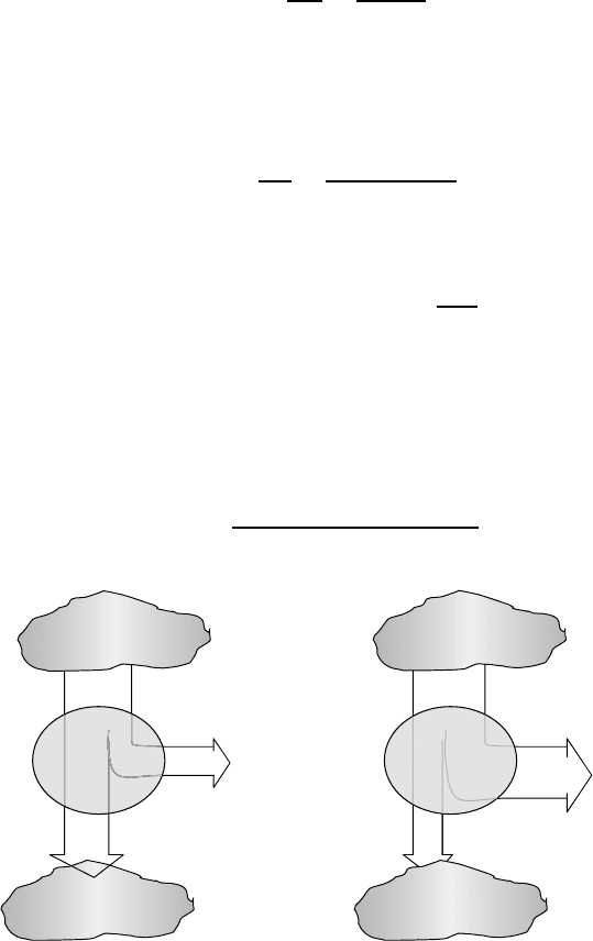
Example 3.1 Entropy Analysis of a Heat Engine. Consider a 40% efficient
heat engine operating between a large, high-temperature reservoir at 1000 K
(727
◦
C) and a large, cold reservoir at 300 K (27
◦
C).
a. If it withdraws 10
6
J/s from the high-temperature reservoir, what would be
the rate of loss of entropy from that reservoir and what would be the rate
of gain by the low-temperature reservoir?
b. Express the work done by the engine in watts.
c. What would be the total entropy gain of the system?
126 THE ELECTRIC POWER INDUSTRY
Solution
a. The loss of entropy from the high-temperature source would be
S
loss
=
Q
H
T
H
=
10
6
J/s
1000 K
= 1000 J/s · K
Since 40% of the heat removed from the source is converted into work,
the remaining 60% is heat transfer into the cold-temperature sink. The rate
of entropy gain by the sink would be
S
gain
=
Q
C
T
C
=
0.60 × 10
6
J/s
300 K
= 2000 J/s · K
c. The heat engine converts 40% of its input energy into work, which is
Work = 0.40 × 10
6
J/s×
1W
J/s
= 400 kW
d. Since there is no entropy associated with the work done by the heat engine,
the total change in entropy of the entire system is the loss from the source
plus the gain to the sink:
S
total
=−1000 + 2000 +0 =+1000 J / s · K
(a) The example (b) A Carnot engine
Q
H
= 10
6
J/s
W = 0.4 × 10
6
J/s
Q
C
= 0.6 × 10
6
J/sK
S
=−1000 J/sK
∆
S
= 2000 J/sK
∆
S
= 0
∆
S
TOTAL
=+1000 J/sK
SOURCE
T
H
= 1000 K
Q
H
= 10
6
J/s
W
= 0.7 × 10
6
J/s
Q
C
= 0.3 × 10
6
J/sK
∆
S
=−1000 J/sK
∆
S
= 1000 J/sK
∆
S
= 0
∆S
TOTAL
= 0 J/sK
SINK
T
C
= 300 K
SINK
T
C
= 300 K
SOURCE
T
H
= 1000 K
70% eff
HEAT
ENGINE
40% eff
HEAT
ENGINE
Figure 3.17 Energy and entropy analysis of two heat engines. The example heat engine
(a) shows a net increase in entropy, while the Carnot engine (b) does not.
STEAM-CYCLE POWER PLANTS 127
The fact that there was a net increase in entropy in Example 3.1 tells us the
engine hasn’t violated the Carnot efficiency limit, which from (3.14) we know
would be 70% for this 1000 K source and 300 K sink. Figure 3.17 summarizes
the energy and entropy analysis for the example heat engine as well as for a
perfect Carnot engine.
3.5 STEAM-CYCLE POWER PLANTS
Conventional thermal power plants can be categorized by the thermodynamic
cycles they utilize when converting heat into work. Utility-scale thermal power
plants are based on either (a) the Rankine cycle, in which a working fluid is alter-
nately vaporized and condensed, or (b) the Brayton cycle, in which the working
fluid remains a gas throughout the cycle. Most baseload thermal power plants,
which operate more or less continuously, are Rankine cycle plants in which steam
is the working fluid. Most peaking plants, which are brought on line as needed
to cover the daily rise and fall of demand, are gas turbines based on the Brayton
cycle. The newest generation of thermal power plants use both cycles and are
called combined-cycle plants.
3.5.1 Basic Steam Power Plants
The basic steam cycle can be used with any source of heat, including combustion
of fossil fuels, nuclear fission reactions, or concentrated sunlight onto a boiler.
The essence of a fossil-fuel-fired steam power plant is diagrammed in Fig. 3.18.
In the steam generator, fuel is burned in a firing chamber surrounded by a boiler
that transfers heat through metal tubing to the working fluid. Water circulating
through the boiler is converted to high-pressure, high-temperature steam. During
this conversion of chemical to thermal energy, losses on the order of 10% occur
due to incomplete combustion and loss of heat up the stack.
High-pressure steam is allowed to expand through a set of turbine wheels
that spin the turbine and generator shaft. For simplicity, the turbine in Fig. 3.18
is shown as a single unit, but for increased efficiency it may actually consist
of two or sometimes three turbines in which the exhaust steam from a higher-
pressure turbine is reheated and sent to a lower-pressure turbine, and so forth.
The generator and turbine share the same shaft allowing the generator to convert
the rotational energy of the shaft into electrical power that goes out onto trans-
mission lines for distribution. A well-designed turbine may have an efficiency
approaching 90%, while the generator may have a conversion efficiency even
higher than that.
The spent steam is drawn out of the last turbine stage by the partial vacuum
created in the condenser as the cooled steam undergoes a phase change back to
the liquid state. The condensed steam is then pumped back to the boiler to be
reheated, completing the cycle.
The heat released when the steam condenses is transferred to cooling water,
which circulates through the condenser. Usually, cooling water is drawn from a