Masters G.M. Renewable and Efficient Electric Power Systems
Подождите немного. Документ загружается.


328 WIND POWER SYSTEMS
so the overall efficiency of the wind turbine, from wind to electricity, is
Overall efficiency =
600 kW
2112 kW
= 0.284 = 28.4%
Notice that if the rotor itself is about 43% efficient, as Fig. 6.11 suggests,
then the efficiency of the gear box times the efficiency of the generator
would be about 66% (43% × 66% = 28.4%).
The answers derived in the above example are fairly typical for large wind
turbines. That is, a large turbine will spin at about 20–30 rpm; the gear box will
speed that up by roughly a factor of 50–70; and the overall efficiency of the
machine is usually in the vicinity of 25–30%. In later sections of the chapter,
we will explore these factors more carefully.
6.6 WIND TURBINE GENERATORS
The function of the blades is to convert kinetic energy in the wind into rotating
shaft power to spin a generator that produces electric power. Generators consist
of a rotor that spins inside of a stationary housing called a stator. Electricity is
created when conductors move through a magnetic field, cutting lines of flux
and generating voltage and current. While small, battery-charging wind turbines
use dc generators, grid-connected machines use ac generators as described in the
following sections.
6.6.1 Synchronous Generators
In Chapter 3, the operation of synchronous generators, which produce almost
all of the electric power in the world, were described. Synchronous generators
are forced to spin at a precise rotational speed determined by the number of
poles and the frequency needed for the power lines. Their magnetic fields are
created on their rotors. While very small synchronous generators can create the
needed magnetic field with a permanent magnet rotor, almost all wind turbines
that use synchronous generators create the field by running direct current through
windings around the rotor core.
The fact that synchronous generator rotors needs dc current for their field
windings creates two complications. First, dc has to be provided, which usually
means that a rectifying circuit, called the exciter, is needed to convert ac from
the grid into dc for the rotor. Second, this dc current needs to make it onto the
spinning rotor, which means that slip rings on the rotor shaft are needed, along
with brushes that press against them. Replacing brushes and cleaning up slip rings
adds to the maintenance needed by these synchronous generators. Figure 6.12
shows the basic system for a wind turbine with a synchronous generator, including
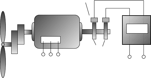
WIND TURBINE GENERATORS 329
Blades
Synchronous generator
Gear box
3
Φ ac output
ac input
Slip rings
Brushes
dc
Exciter
Figure 6.12 A three-phase synchronous generator needs dc for the rotor windings, which
usually means that slip rings and brushes are needed to transfer that current to the rotor
from the exciter.
a reminder that the generator and blades are connected through a gear box to
match the speeds required of each.
6.6.2 The Asynchronous Induction Generator
Most of the world’s wind turbines use induction generators rather than the syn-
chronous machines just described. In contrast to a synchronous generator (or
motor), induction machines do not turn at a fixed speed, so they are often
described as asynchronous generators. While induction generators are uncom-
mon in power systems other than wind turbines, their counterpart, induction
motors, are the most prevalent motors around—using almost one-third of all the
electricity generated worldwide. In fact, an induction machine can act as a motor
or generator, depending on whether shaft power is being put into the machine
(generator) or taken out (motor). Both modes of operation, as a motor during
start-up and as a generator when the wind picks up, take place in wind turbines
with induction generators. As a motor, the rotor spins a little slower than the
synchronous speed established by its field windings, and in its attempts to “catch
up” it delivers power to its rotating shaft. As a generator, the turbine blades spin
the rotor a little faster than the synchronous speed and energy is delivered into
its stationary field windings.
The key advantage of asynchronous induction generators is that their rotors
do not require the exciter, brushes, and slip rings that are needed by most syn-
chronous generators. They do this by creating the necessary magnetic field in
the stator rather than the rotor. This means that they are less complicated and
less expensive and require less maintenance. Induction generators are also a little
more forgiving in terms of stresses to the mechanical components of the wind
turbine during gusty wind conditions.
330 WIND POWER SYSTEMS
Rotating Magnetic Field. To understand how an induction generator or motor
works, we need to introduce the concept of a rotating magnetic field. Begin
by imagining coils imbedded in the stator of a three-phase generator as shown
in Fig. 6.13. These coils consist of copper conductors running the length of
the stator, looping around, and coming back up the other side. We will adopt
the convention that positive current in any phase means that current flows from
the unprimed letter to the primed one (e.g., positive i
A
means that current flows
from A to A
). When current in a phase is positive, the resulting magnetic field
is drawn with a bold arrow; when it is negative, a dashed arrow is used. And
remember the arrow symbolism: a “+” at the end of a wire means current flow
into the page, while a dot means current flow out of the page.
Now, consider the magnetic fields that result from three-phase currents flowing
in the stator. In Fig. 6.14a, the clock is stopped at ωt = 0, at which point i
A
reaches its maximum positive value, and i
B
and i
C
are both negative and equal
in magnitude. The magnetic flux for each of the three currents is shown, the
sum of which is a flux arrow that points vertically downward. A while later, let
us stop the clock at ωt = π/3 = 60
◦
.Nowi
A
= i
B
and both are positive, while
i
C
is now its maximum negative value, as shown in Fig. 6.14b. The resultant
sum of the fluxes has now rotated 60
◦
in the clockwise direction. We could
continue this exercise for increasing values of ωt and we would see the resultant
flux continuing to rotate around. This is an important concept for the inductance
generator: With three-phase currents flowing in the stator, a rotating magnetic
field is created inside the generator. The field rotates at the synchronous speed
N
s
determined by the frequency of the currents f and the number of poles p.
That is, N
s
= 120f/p, as was the case for a synchronous generator.
The Squirrel Cage Rotor. A three-phase induction generator must be supplied
with three-phase ac currents, which flow through its stator, establishing the rotat-
ing magnetic field described above. The rotor of many induction generators (and
motors) consists of a number of copper or aluminum bars shorted together at their
ends, forming a cage not unlike one you might have to give your pet rodent some
+
+
A
A
i
A
i
A
Φ
A
A
′
A
i
A
i
A
Φ
A
A
′
B
Positive current Negative current
CB
′
C
′
A
′
Figure 6.13 Nomenclature for the stator of an inductance generator. Positive current
flow from A to A
results in magnetic flux
A
represented by a bold arrow pointing
downward. Negative current (from A
to A) results in magnetic flux represented by a
dotted arrow pointing up.
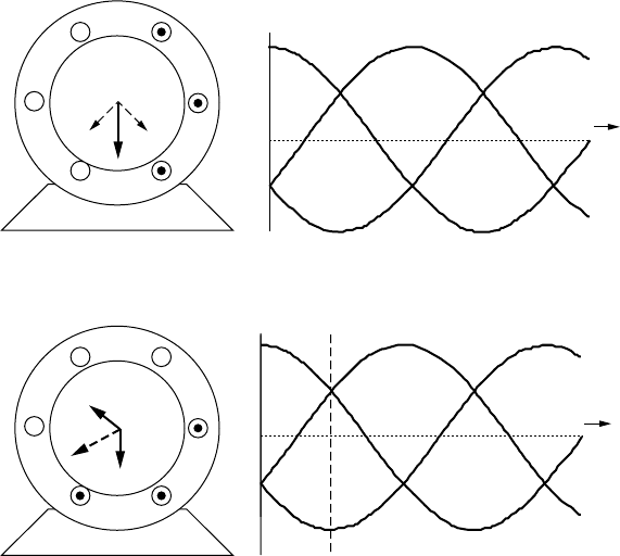
WIND TURBINE GENERATORS 331
(a)
A
C
B
+
+
+
C
′
A
′
A
′
B
′
Φ
C
Φ
B
w
t
= 0
i
A
i
B
i
C
i
A
i
B
i
C
w
t
(b)
++
+
A
C
B
C
′
B
′
Φ
C
Φ
A
Φ
A
Φ
B
w
t
= p/3
w
t
Figure 6.14 (a) At ωt = 0,i
A
is a positive maximum while i
B
and i
C
are both negative
and equal to each other. The resulting sum of the magnetic fluxes points straight down;
(b) at ωt = π/3, the magnetic flux vectors appear to have rotated clockwise by 60
◦
.
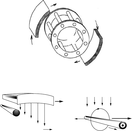
exercise. They used to be called “squirrel” cage rotors, but now they are just cage
rotors. The cage is then imbedded in an iron core consisting of thin (0.5 mm)
insulated steel laminations. The laminations help control eddy current losses (see
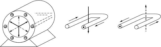
Section 1.8.2). Figure 6.15 shows the basic relationship between stator and rotor,
which can be thought of as a pair of magnets (in the stator) spinning around the
cage (rotor).
To understand how the rotating stator field interacts with the cage rotor, con-
sider Fig. 6.16a. The rotating stator field is shown moving toward the right, while
the conductor in the cage rotor is stationary. Looked at another way, the stator
field can be thought to be stationary and, relative to it, the conductor appears
to be moving to the left, cutting lines of magnetic flux as shown in Fig. 6.16b.
Faraday’s law of electromagnetic induction (see Section 1.6.1) says that when-
ever a conductor cuts flux lines, an emf will develop along the conductor and,
if allowed to, current will flow. In fact, the cage rotor has thick conductor bars
with very little resistance, so lots of current can flow easily. That rotor current,
labeled i
R
in Fig. 6.16b, will create its own magnetic field, which wraps around
332 WIND POWER SYSTEMS
Magnetic field created in
stator appears to rotate
N
Cage
rotor
S
Figure 6.15 A cage rotor consisting of thick, conducting bars shorted at their ends,
around which circulates a rotating magnetic field.
N
Moving stator field
Stationary cage
conductor
Φ
S
(a)
i
R
FORCE
Relative
conductor
motion
Stator field
Φ
S
φ
R
(b)
Figure 6.16 In (a) the stator field moves toward the right while the cage rotor conductor
is stationary. As shown in (b), this is equivalent to the stator field being stationary while
the conductor moves to the left, cutting lines of flux. The conductor then experiences a
force that tries to make the rotor want to catch up to the stator’s rotating magnetic field.
the conductor. The rotor’s magnetic field then interacts with the stator’s magnetic
field, producing a force that attempts to drive the cage conductor to the right. In
other words, the rotor wants to spin in the same direction that the rotating stator
field is revolving—in this case, clockwise.
The Inductance Machine as a Motor. Since it is easier to understand an
induction motor than an induction generator, we’ll start with it. The rotating
magnetic field in the stator of the inductance machine causes the rotor to spin in
the same direction. That is, the machine is a motor—an induction motor. Notice
that there are no electrical connections to the rotor; no slip rings or brushes are
required. As the rotor approaches the synchronous speed of the rotating magnetic
field, the relative motion between them gets smaller and smaller and less and less
force is exerted on the rotor. If the rotor could move at the synchronous speed,
there would be no relative motion, no current induced in the cage conductors, and
no force developed to keep the rotor going. Since there will always be friction to
WIND TURBINE GENERATORS 333
Slip
0
1
2
Torque
Breakdown torque
Braking
Linear region,
motoring
Figure 6.17 The torque– slip curve for an inductance motor.
overcome, the induction machine operating as a motor spins at a rate somewhat
slower than the synchronous speed determined by the stator. This difference in
speed is called slip, which is defined mathematically as
s =
N
S
− N
R
N
S
= 1 −
N
R
N
S
(6.28)
where s is the rotor slip, N
S
is the no-load synchronous speed = 120f/p rpm,
where f is frequency and p is poles, and N
R
is the rotor speed.
As the load on the motor increases, the rotor slows down, increasing the
slip, until enough torque is generated to meet the demand. In fact, for most
induction motors, slip increases quite linearly with torque within the usual range
of allowable slip. There comes a point, however, when the load exceeds what is
called the “breakdown torque” and increasing the slip no longer satisfies the load
and the rotor will stop (Fig. 6.17). If the rotor is forced to rotate in the opposite
direction to the stator field, the inductance machine operates as a brake.
Example 6.8 Slip for an induction motor A 60-Hz, four-pole induction
motor reaches its rated power when the slip is 4%. What is the rotor speed
at rated power?
The no-load synchronous speed of a 60-Hz, four-pole motor is
N
s
=
120f
p
=
120 × 60
4
= 1800 rpm
From (6.28) at a slip of 4%, the rotor speed would be
N
R
= (1 − s)N
S
= (1 − 0.04) · 1800 = 1728 rpm
The Inductance Machine as a Generator. When the stator is provided with
three-phase excitation current and the shaft is connected to a w ind turbine and
334 WIND POWER SYSTEMS
gearbox, the machine will start operation by motoring up toward its synchronous
speed. When the windspeed is sufficient to force the generator shaft to exceed
synchronous speed, the induction machine automatically becomes a three-phase
generator delivering electrical power back to its stator windings. But where does
the three-phase magnetization current come from that started this whole pro-
cess? If it is grid-connected, the power lines provide that current. It is possible,
however, to have an induction generator provide its own ac excitation current
by incorporating external capacitors, which allows for power generation without
the grid.
The basic concept for a self-excited generator is to create a resonance condi-
tion between the inherent inductance of the field windings in the stator and the
external capacitors that have been added. A capacitor and an inductor connected
in parallel form the basis for electronic oscillators; that is, they have a resonant
frequency at which they will spontaneously oscillate if given just a nudge in
that direction. That nudge is provided by a remnant magnetic field in the rotor.
The oscillation frequency, and hence the rotor excitation frequency, depends on
the size of the external capacitors, which provides one way to control wind
turbine speed. In Fig. 6.18, a single-phase, self-excited, induction generator is
diagrammed showing the external capacitance.
So how fast does an inductance generator spin? The same slip factor definition
as was used for inductance motors applies [Eq. (6.28)], except that now the slip
will be a negative number since the rotor spins faster than synchronous speed.
For grid-connected inductance generators, the slip is normally no more than about
1%. This means, for example, that a two-pole, 60-Hz generator with synchronous
speed 3600 rpm will turn at about
N
R
= (1 − s)N
S
= [1 − (−0.01)] · 3600 = 3636 rpm
An added bonus with induction generators is they can cushion the shocks caused
by fast changes in wind speed. When the windspeed suddenly changes, the slip
increases or decreases accordingly, which helps absorb the shock to the wind
turbine mechanical equipment.
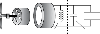
Load
Stator
inductance
External capacitance
added
Cage rotor
Figure 6.18 A self-excited inductance generator. External capacitors resonate with the
stator inductance causing oscillation at a particular frequency. Only a single phase
is shown.
SPEED CONTROL FOR MAXIMUM POWER 335
6.7 SPEED CONTROL FOR MAXIMUM POWER
In this section we will explore the role that the gear box and generator have
with regard to the rotational speed of the rotor and the energy delivered by the
machine. Later, we will describe the need for speed control of rotor blades to
be able to shed wind to prevent overloading the turbine’s electrical components
in highwinds.
6.7.1 Importance of Variable Rotor Speeds
There are other reasons besides shedding high-speed winds that rotor speed con-
trol is an important design task. Recall Fig. 6.11, in which rotor efficiency C
p
was shown to depend on the tip-speed ratio, TSR. Modern wind turbines oper-
ate best when their TSR is in the range of around 4–6, meaning that the tip
of a blade is moving 4–6-times the wind speed. Ideally, then, for maximum
efficiency, turbine blades should change their speed as the windspeed changes.
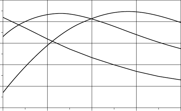
Figure 6.19 illustrates this point by showing an example of blade efficiency ver-
sus wind speed with three discrete steps in rotor rpm as a parameter. Unless the
rotor speed can be adjusted, blade efficiency C
p
changes as wind speed changes.
It is interesting to note, however, that C
p
is relatively flat near its peaks so that
continuous adjustment of rpm is only modestly better than having just a few
discrete rpm steps available.
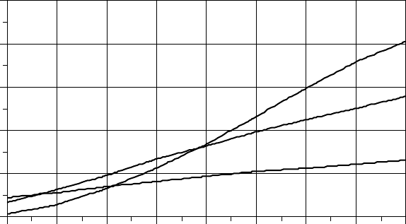
While Fig. 6.19 shows the impact of rotor speed on blade efficiency, what
is more important is electric power delivered by the wind turbine. Figure 6.20
15131197
0.0
0.1
0.2
0.3
0.4
0.5
Wind speed (m/s)
Blade efficiency,
C
p
20 rpm
30 rpm
40 rpm
Figure 6.19 Blade efficiency is improved if its rotation speed changes with changing
wind speed. In this figure, three discrete speeds are shown for a hypothetical rotor.
336 WIND POWER SYSTEMS
Wind speed (m/s)
151413121110987
0
100
200
300
400
500
20 rpm
30 rpm
40 rpm
Power delivered (kW)
Figure 6.20 Example of the impact that a three-step rotational speed adjustment has
on delivered power. For winds below 7.5 m/s, 20 rpm is best; between 7.5 and 11 m/s,
30 rpm is best; and above 11 m/s, 40 rpm is best.
shows the impact of varying rotor speed from 20 to 30 to 40 rpm for a 30-m
rotor with efficiency given in Fig. 6.19, along with an assumed gear and generator
efficiency of 70%.
While blade efficiency benefits from adjustments in speed as illustrated in
Figs. 6.19 and 6.20, the generator may need to spin at a fixed rate in order to
deliver current and voltage in phase with the grid that it is feeding. So, for
grid-connected turbines, the challenge is to design machines that can somehow
accommodate variable rotor speed and somewhat fixed generator speed—or at
least attempt to do so. If the wind turbine is not grid-connected, the generator
electrical output can be allowed to vary in frequency (usually it is converted to
dc), so this dilemma isn’t a problem.
6.7.2 Pole-Changing Induction Generators
Induction generators spin at a frequency that is largely controlled by the number
of poles. A two-pole, 60-Hz generator rotates at very close to 3600 rpm; with
four poles it rotates at close to 1800 rpm; and so on. If we could change the
number of poles, we could allow the wind turbine to have several operating
speeds, approximating the performance shown in Figs. 6.19 and 6.20. A key to
this approach is that as far as the rotor is concerned, the number of poles in
the stator of an induction generator is irrelevant. That is, the stator can have
external connections that switch the number of poles from one value to another
without needing any change in the rotor. This approach is common in household
appliance motors such as those used in washing machines and exhaust fans to
give two- or three-speed operation.
SPEED CONTROL FOR MAXIMUM POWER 337
6.7.3 Multiple Gearboxes
Some wind turbines have two gearboxes with separate generators attached to
each, giving a low-wind-speed gear ratio and generator plus a high-wind-speed
gear ratio and generator.
6.7.4 Variable-Slip Induction Generators
A normal induction generator maintains its speed within about 1% of the syn-
chronous speed. As it turns out, the slip in such generators is a f unction of the
dc resistance in the rotor conductors. By purposely adding variable resistance to
the rotor, the amount of slip can range up to around 10% or so, which would
mean, for example, that a four-pole, 1800-rpm machine could operate anywhere
from about 1800 to 2000 rpm. One way to provide this capability is to have
adjustable resistors external to the generator, but the trade-off is that now an
electrical connection is needed between the rotor and resistors. That can mean
abandoning the elegant cage rotor concept and instead using a wound rotor with
slip rings and brushes similar to what a synchronous generator has. And that
means more maintenance will be required.
Another way to provide variable resistance for the rotor is to physically mount
the resistors and the electronics that are needed to control them on the rotor itself.
But then you need some way to send signals to the rotor telling it how much slip
to provide. In one system, called Opti Slip
, an optical fiber link to the rotor is
used for this communication.
6.7.5 Indirect Grid Connection Systems
In this approach, the wind turbine is allowed to spin at whatever speed that
is needed to deliver the maximum amount of power. When attached to a syn-
chronous or induction generator, the electrical output will have variable frequency
depending on whatever speed the wind turbine happens to have at the moment.
This means that the generator cannot be directly connected to the utility grid,
which of course requires fixed 50- or 60-Hz current.
Figure 6.21 shows the basic concept of these indirect systems. Variable-
frequency ac from the generator is rectified and converted into dc using high-
power transistors. This dc is then sent to an inverter that converts it back to ac, but
this time with a steady 50- or 60-Hz frequency. The raw output of an inverter is
pretty choppy and needs to be filtered to smooth it. As described in Chapter 2, any
time ac is converted to dc and back again, there is the potential for harmonics to
be created, so one of the challenges associated with these variable-speed, indirect
wind turbine systems is maintaining acceptable power quality.
In addition to higher annual energy production, variable-speed wind turbines
have an advantage of greatly minimizing the wear and tear on the whole system
caused by rapidly changing wind speeds. When gusts of wind hit the turbine,
rather than having a burst of torque hit the blades, drive shaft, and gearbox,