Masters G.M. Renewable and Efficient Electric Power Systems
Подождите немного. Документ загружается.

508 PHOTOVOLTAIC SYSTEMS
9.2 CURRENT–VOLTAGE CURVES FOR LOADS
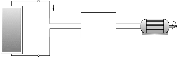
While the I –V curve for a photovoltaic cell, module, or array defines the com-
binations of voltage and current that are permissible under the existing ambient
conditions, it does not by itself tell us anything about just where on that curve
the system will actually be operating. This determination is a function of the load
into which the PVs deliver their power. Just as PVs have an I –V curve, so do
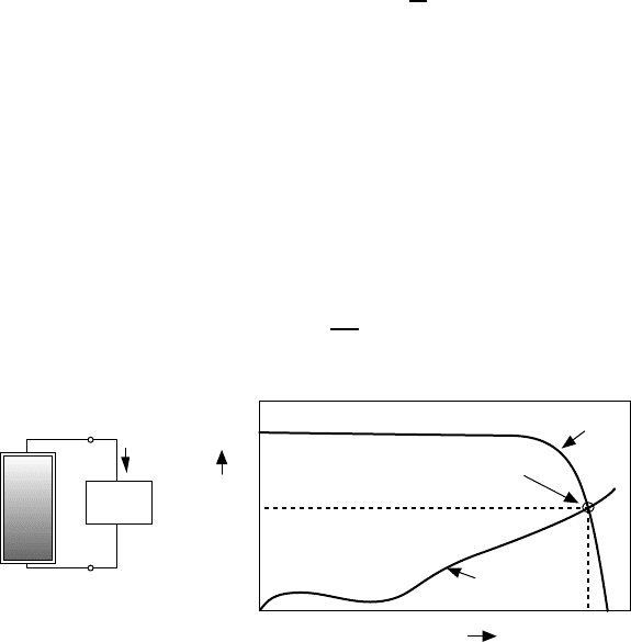
loads. As shown in Fig. 9.4, the same voltage is across both the PVs and load,
and the same current runs through the PVs and load. Therefore, when the I –V
curve for the load is plotted onto the same graph that has the I –V curve for the
PVs, the intersection point is the one spot at which both the PVs and load are
satisfied. This is called the operating point.
9.2.1 Simple Resistive-Load I–V Curve
To illustrate the importance and need for load curves, consider a simple resistive
load as shown in Fig. 9.5. For the load,
V = IR or I =
1
R
V(9.1)
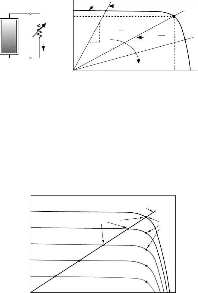
which, when plotted on current versus voltage axes, is a straight line with slope
1/R.AsR increases, the operating point where the PV and resistance I –V curves
intersect moves along the PV I –V curve from left to right. In fact, that suggests
a simple way to actually measure the I –V curve for PV module. By using a
variable resistance, called a potentiometer, or pot, as the load, and then varying
its resistance, pairs of current and voltage can be obtained, which can be plotted
to give the module I –V curve.
Since power delivered to any load is the product of current and voltage, there
will be one particular value of resistance that will result in maximum power:
R
m
=
V
m
I
m
(9.2)
LOAD
V
0
V
0
I
0
I
0
+
-
P
=
V
0
I
0
VOLTAGE
CURRENT
I
−
V
curve
for the load
PV
I
−
V
curve
Operating
point
Figure 9.4 The operating point is the intersection of the current–voltage curves for the
load and the PVs.
CURRENT–VOLTAGE CURVES FOR LOADS 509
I
+
−
V
=
RI
VOLTAGE
CURRENT
R
Slope =
1
R
I
m
Increasing R
MPP
pot
R
m
=
V
m
V
m
I
m
Resistor
I
−
V
curve
PV
I
−
V
Figure 9.5 A module supplying power to a resistive load. As resistance changes, the
operating point moves around on the PV I –V curve.
where V
m
and I
m
are the voltage and current at the maximum power point (MPP).
Under the special conditions at which modules are tested, the MPP corresponds to
the rated voltage V
R
and current I
R
of the module. That means the best value of
resistance, for maximum power transfer, should be V
R
/I
R
under 1-sun, 25
◦
C, AM
1.5 conditions. As Fig. 9.6 shows, however, with a fixed resistance the operating
point slips off the MPP as conditions change and the module becomes less and
less efficient. Later, a device called a maximum power point tracker (MPPT) will
be introduced, the purpose of which is to keep the PVs operating at their highest
efficiency point at all times.
VOLTAGE
CURRENT
1000 W/m
2
800 W/m
2
600 W/m
2
400 W/m
2
200 W/m
2
Fixed
resistance load
Operating
points
MPPs
Figure 9.6 The efficiency of a PV module with a fixed resistance load designed for
1-sun conditions will decline with changing insolation. The solid maximum power point
(MPP) dots show the operating points that would result in maximum PV efficiency.
510 PHOTOVOLTAIC SYSTEMS
9.2.2 DC Motor I–V Curve
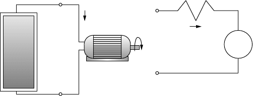
While it is not often that a load would be an actual resistor, dc motors, such
as those often used in PV-water-pumping systems, do exhibit a current–voltage
relationship that is quite similar to that of a resistor. Most are permanent-magnet
dc motors, which can be modeled as shown in Fig. 9.7. Notice that as the motor
spins, it develops a back electromotive force e, which is a voltage proportional to
the speed of the motor (ω) that opposes the voltage supplied by the photovoltaics.
From the equivalent circuit, the voltage–current relationship for the dc motor
is simply
V = IR
a
+ kω (9.3)
where back emf e = kω and R
a
is the armature resistance.
A dc motor runs at nearly constant speed for any given applied voltage even
though the torque requirement of its load may change. For example, as the torque
requirement increases, the motor slows slightly, which drops the back emf and
allows more armature current to flow. Since motor torque is proportional to
armature current, the slowing motor draws more current, delivers more torque to
the load, and regains almost all of its lost speed.
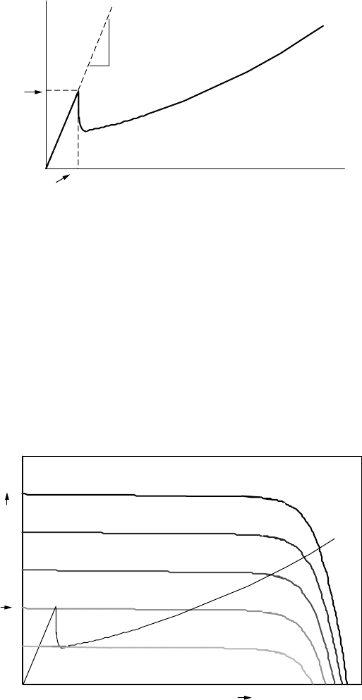
Based on (9.3), the electrical characteristic curve of a dc motor will appear
to be something like the one shown in Fig. 9.8. Notice that at start-up, while
ω = 0, the current rises rapidly with increasing voltage until current is sufficient
to create enough starting torque to break the motor loose from static friction.
Once the motor starts to spin, back emf drops the current and thereafter I rises
more slowly with increasing voltage. Notice that if you stall a dc motor while
the voltage is way above the starting voltage, the current may be so high that the
armature windings will burn out. That is why you should never leave the power
on a dc motor if the armature is mechanically stuck for some reason.
A dc motor I –V curve is superimposed on a set of photovoltaic I –V curves
in Fig. 9.9. The mismatch of operating points with the ideal MPP is apparent.
Notice in this somewhat exaggerated example that the motor doesn’t have enough
current to overcome static friction until insolation reaches at least 400 W/m
2
.
Once it starts spinning, however, it only needs about 200 W/m
2
to keep running.
V
w
I
+
−
dc
motor
+
−
e
=
k
w
R
a
+
−
I
dc motor
equivalent circuit
V
Figure 9.7 Electrical model of a permanent magnet dc motor.
CURRENT–VOLTAGE CURVES FOR LOADS 511
MOTOR VOLTAGE
CURRENT
Starting
current
1
R
a
w = 0
w increasing with
V
Starting voltage
Figure 9.8 Electrical characteristics of a permanent-magnet dc motor.
This could mean that a fair amount of insolation is unusable in the morning while
the motor struggles to break loose, which adds to the inefficiency of this simple
PV–motor setup.
There is a device, called a linear current booster (LCB), that is designed to
help overcome this loss of potentially usable insolation when current delivered to
the motor is insufficient to overcome friction (Fig. 9.10). Notice from the I –V
curves of Fig. 9.9 that the operating point in the morning is nowhere near the
knee of the insolation curve where maximum power is available. Out by the
knee of the curve, the PVs may be able to supply enough power to overcome
friction, but without some clever electronics, this power would be delivered with
VOLTAGE
CURRENT
1000 W/m
2
800 W/m
2
600 W/m
2
400 W/m
2
200 W/m
2
Motor
I
−
V
Start-up
current
Figure 9.9 DC motor I –V curve on photovoltaic I –V curves for varying insolation.
In this example (somewhat exaggerated), the motor won’t start spinning until insolation
reaches 400 W/m
2
, but after that it only needs 200 W/m
2
to keep running.
512 PHOTOVOLTAIC SYSTEMS
V
I
+
−
Linear
Current
Booster
Low
I
High
V
High
I
Low
V
w
dc
motor
Figure 9.10 A linear current booster (LCB) increases current to help start or keep the
motor running in low sunlight.
relatively low current and relatively high voltage and still wouldn’t start the
motor. What an LCB does is to shift this relationship around. By converting
low-current, high-voltage power into high-current, low-voltage power, they can
get the motor started earlier in the morning. The lower voltage, however, means
that the motor will spin at a slower rate, but at least it is working. In addition,
the motor with an LCB will not stall as early in the afternoon, though it will
slow down. So there are additional gains.
9.2.3 Battery I–V Curves
Since PVs only provide power during the daylight hours and many applications
require energy when the sun isn’t shining, some method of energy storage often
is needed. For a water pumping system, this might be the potential energy of
water stored in a tank. For grid-connected systems, the utility lines themselves
can be thought of as the storage mechanism: PV energy is put onto the grid
during the day and taken back at night. For most off-grid applications, however,
energy is stored in batteries for use whenever it is needed.
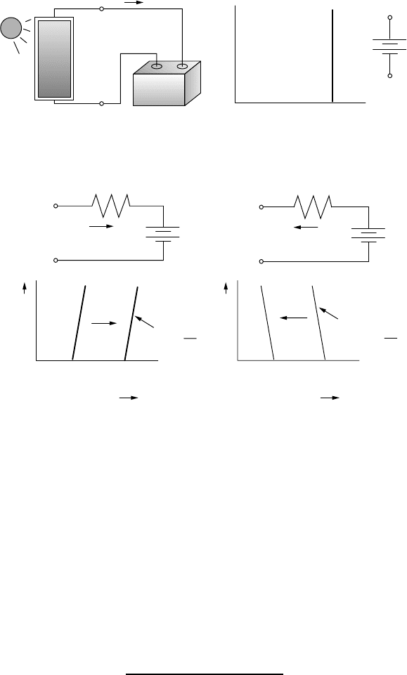
An ideal battery is one in which the voltage remains constant no matter how
much current is drawn. This means that it will have an I –V curve that is simply
a straight up-and-down line as shown in Fig. 9.11. A real battery, on the other
hand, has some internal resistance and is often modeled with an equivalent circuit
consisting of an ideal battery of voltage V
B
in series with some internal resistance
R
i
as shown in Fig. 9.12. During the charge cycle, with positive current flow into
the battery, we can write
V = V
B
+ R
i
I(9.4)
which plots as a slightly-tilted, straight line with slope equal to 1/R
i
.During
charging, the applied voltage needs to be greater than V
B
; as the process contin-
ues, V
B
itself increases so the I –V line slides to the right as shown in Fig. 9.12a.
During discharge, the output voltage of the battery is less than V
B
, the slope
of the I –V line flips, and the I –V curve moves back to the left as shown in
Fig. 9.12b.
CURRENT–VOLTAGE CURVES FOR LOADS 513
+
−
+
−
I
V
V
B
VOLTAGE
V
B
CURRENT
Ideal
Battery
V
=
V
B
+
−
V
B
Symbol
BATTERY
Figure 9.11 An ideal battery has a vertical current–voltage characteristic curve.
+
V
B
R
i
V
I
+
−
−
VOLTAGE
CURRENT
slope
=
1
R
i
charging
(a) Charging
V
>
V
B
+
V
B
R
i
V
I
+
−
−
V
<
V
B
(b) Discharging
V
B
discharged
V
B
charged
VOLTAGE
CURRENT
slope
=
1
−
R
i
discharging
V
B
discharged
V
B
charged
Figure 9.12 A real battery can be modeled as an ideal battery in series with its internal
resistance, with current flowing in opposite directions during charging (a) and discharging
(b). During charging/discharging, the slightly tilted I –V curve slides right or left.
The simple equivalent circuit representation of Fig. 9.12 is complicated by a
number of factors, including the fact that the open-circuit voltage (V
B
) depends
not only on the state of charge but also on battery temperature and how long
it has been resting without any current flowing. For a conventional 12-V lead-
acid battery at 78
◦
F, which has been allowed to rest for a few hours, V
B
ranges
from 12.7 V for a fully charged battery to about 11.7 V for one that has only
a few percent of its charge remaining. Internal resistance is also a function of
temperature and state of charge, as well the age and condition of the battery.
Example 9.1 Charging a 12-volt Battery. Suppose that a nearly depleted
12-V lead-acid battery has an open-circuit voltage of 11.7 V and an internal
resistance of 0.03 .

514 PHOTOVOLTAIC SYSTEMS
a. What voltage would a PV module operate at if it is delivering 6 A to
the battery?
b. If 20 A is drawn from a fully charged battery with open-circuit voltage
12.7 V, what voltage would the PV module operate at?
Solution
a. Using (9.4), the PV voltage would be
V = V
B
+ R
i
I = 11.7 + 0.03 × 6 = 11.88 V
b. While drawing 20 A after V
B
has reached 12.7 V, the output voltage of
the battery would be
V
load
= V
B
− IR
i
= 12.7 − 20 × 0.03 = 12.1V
and since the voltage that the PVs operate at is determined by the battery
voltage, they would also be at 12.1 V.
Since the I –V curve for a battery moves toward the right as the battery gains
charge during the day, there is a chance that the PV operating point will begin
to slide off the edge of the knee—especially late in the day when the knee
itself is moving toward the left. This may not be a bad thing, however, since
current has to be slowed or stopped anyway when a battery reaches full charge.
If the PV–battery system has a charge controller, it will automatically prevent
overcharging of the batteries. For very small battery charging systems, however,
the charge controller can sometimes be omitted if modules with fewer cells in
series are used. Such self-regulating modules sometimes have 33, or even 30,
cells instead of the usual 36 to purposely cause the current to drop off as the
battery approaches full charge as shown in Fig. 9.13.
9.2.4 Maximum Power Point Trackers
Clearly, significant efficiency gains could be realized if the operating points for
resistive, dc motor, and battery loads could somehow be kept near the knee of
the PV I –V curves throughout the ever-changing daily conditions. Devices to
do just that, called maximum power trackers (MPPTs), are available and are a
standard part of many PV systems—especially those that are grid-connected.
There are some very clever, quite simple circuits that are at the heart of not
only MPPTs but also linear current boosters (LCBs) as well as a number of
other important power devices. The key is to be able to convert dc voltages
from one level to another—something that was very difficult to do efficiently
before high-power, field-effect transistors (FETs) became available in the 1980s
and insulated-gate bipolar transistors (IGBTs) became available in the 1990s. At
CURRENT–VOLTAGE CURVES FOR LOADS 515
VOLTAGE (V)
CURRENT (A)
NOON
LATE AFTERNOON
Discharged Charged
36 cells
30 cells
36
30
Figure 9.13 A self-regulating PV module with fewer cells can automatically reduce
charging current as the batteries approach full charge.
the heart of modern switched-mode dc-to-dc converters is one of these transistors
used as a simple on–off switch that either allows current to pass or blocks it.
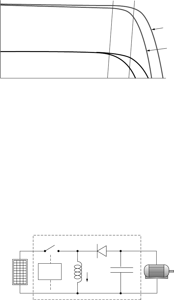
A boost converter is a commonly used circuit to step up the voltage from a
dc source, while a buck converter is often used to step down voltage. The circuit
of Fig. 9.14 is a combination of these two circuits and is called a buck-boost
converter. A buck-boost converter is capable of raising or lowering a dc voltage
from its source to whatever dc voltage is needed by the load. The source in this
case is shown as being a PV module and the load is shown as a dc motor, but
the basic concept is used for a wide variety of electric power applications. The
transistor switch flips on and off at a rapid rate (on the order of 20 kHz) under
control of some sensing and logic circuitry that isn’t shown. Also not shown is
a capacitor across the PVs that helps smooth the voltage supplied by the PVs.
To analyze the buck-boost converter, we have to go back to first principles.
Conventional dc or ac circuit analysis doesn’t help much and instead the analysis
V
i
V
L
V
0
L
I
L
C
+
−
switch
Load
Source
Buck-boost converter
+
−
+
−
Switch
control
Figure 9.14 A buck-boost converter used as a the heart of a maximum power tracker.

516 PHOTOVOLTAIC SYSTEMS
is based on an energy balance for the magnetic field of the inductor. Basically
there are two situations to consider: the circuit with the switch closed and the
circuit with the switch open.
When the switch is closed, the input voltage V
i
is applied across the inductor,
driving current I
L
through the inductor. All of the source current goes through
the inductor since the diode blocks any flow to the rest of the circuit. During this
portion of the cycle, energy is being added to the magnetic field in the inductor as
current builds up. If the switch stayed closed, the inductor would eventually act
like a short-circuit and the PVs would deliver short-circuit current at zero volts.
When the switch is opened, current in the inductor continues to flow as the
magnetic field begins to collapse (remember that current through an inductor can-
not be changed instantaneously—to do so would require infinite power). Inductor
current now flows through the capacitor, the load, and the diode. Inductor cur-
rent charging the capacitor provides a voltage (with a polarity reversal) across
the load that will help keep the load powered after the switch closes again.
If the switch is cycled quickly enough, the current through the inductor doesn’t
have a chance to drop much while the switch is open before the next jolt of cur-
rent from the source. With a fast enough switch and a large enough inductor,
the circuit can be designed to have nearly c onstant inductor current. That’s our
first important insight into how this circuit works: Inductor current is essen-
tially constant.
If the switch is cycled quickly enough, the voltage across the capacitor doesn’t
have a chance to drop much while the switch is closed before the next jolt of
current from the inductor charges it back up again. Capacitors, recall, can’t have
their voltage change instantaneously so if the switch is cycling fast enough and
the capacitor is sized large enough, the output voltage across the capacitor and
load is nearly constant. We now have our second insight into this circuit: Output
voltage V
o
is essentially constant (and opposite in sign to V
i
).
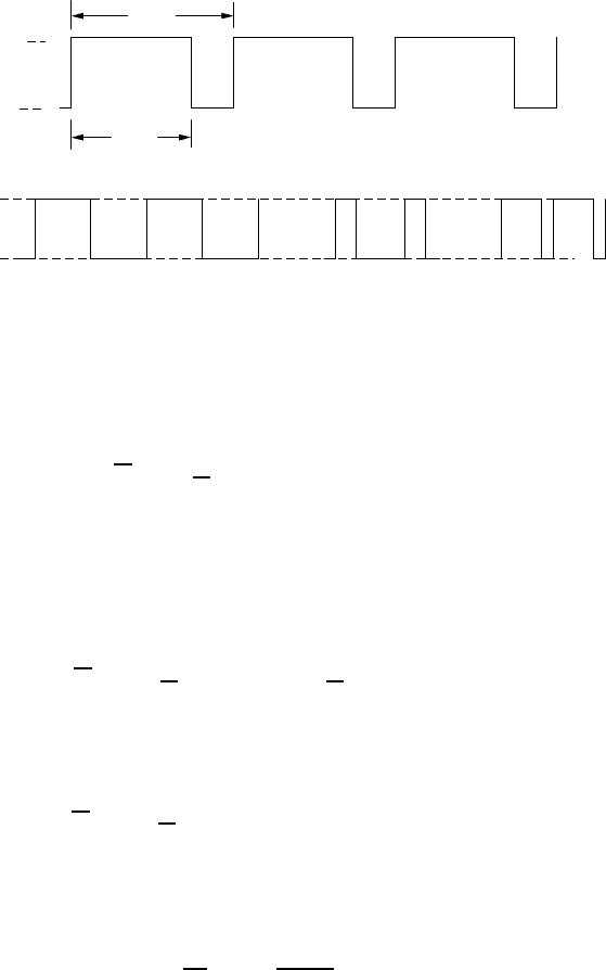
Finally, we need to introduce the duty cycle of the switch itself. This is what
controls the relationship between the input and output voltages of the converter.
The duty cycle D (0 <D<1) is the fraction of the time that the switch is closed,
as illustrated in Fig. 9.15. This variation in the fraction of time the switch is in
one state or the other is referred to as pulse-width modulation (PWM).
For this simple description, all of the components in the converter will be
considered to be ideal. As such, the inductor, diode and capacitor do not consume
any net energy over a complete cycle of the switch. Therefore the average power
into the converter is equal to the average power delivered by the converter; that
is, it has 100% efficiency. Real MPPTs have efficiencies in the mid-90% range,
so this isn’t a bad assumption.
Now focus on the inductor. While the switch is closed, from time t = 0to
t = DT, the voltage across the inductor is a constant V
i
. The average power put
into the magnetic field of the inductor during one complete cycle is given by
P
L,in
=
1
T
DT
0
V
i
I
L
dt =
1
T
V
i
DT
0
I
L
dt (9.5)
CURRENT–VOLTAGE CURVES FOR LOADS 517
T
DT
Open
(off)
Closed
(on)
Closed
Open
(b) D = 0.5
(c) D < 0.5
(d) D > 0.5
(a)
Figure 9.15 The duty cycle D is the fraction of the time the switch is closed (a).
Examples: (b) 50% duty cycle; (c) D < 0.5; (d) D > 0.5.
Under the assumption that inductor current is constant, the average power into
the inductor is
P
L,in
=
1
T
V
i
I
L
DT
0
dt = V
i
I
L
D(9.6)
When the switch opens, the inductor’s magnetic field begins to collapse, return-
ing the energy it just acquired. The diode conducts, which means that the voltage
across the inductor V
L
is the same as the voltage across the load V
0
. The average
power delivered by the inductor is therefore
P
L,out
=
1
T
T
DT
V
L
I
L
dt =
1
T
T
DT
V
0
I
L
dt (9.7)
With good design, both V
0
and I
L
are essentially constant, so average power
from the inductor is
P
L,out
=
1
T
V
0
I
L
(T −DT ) = V
0
I
L
(1 − D) (9.8)
Over a complete cycle, average power into the inductor equals average power
out of the inductor. So, from (9.6) and (9.8), we get
V
0
V
i
=−
D
1 − D
(9.9)
Equation (9.9) is pretty interesting. It tells us we can bump dc voltages up or
down (there is a sign change) just by varying the duty cycle of the buck-boost
converter. Longer duty cycles allow more time for the capacitor to charge up and
less time for it to discharge, so the output voltage increases as D increases. For
a duty cycle of 1/2, the output voltage is the same as the input voltage. A duty
cycle of 2/3 results in a doubling of voltage, while D = 1/3 cuts voltage in half.