Masters G.M. Renewable and Efficient Electric Power Systems
Подождите немного. Документ загружается.


568 PHOTOVOLTAIC SYSTEMS
c. At C/20, the current is 100 Ah/20 h = 5 A . The input voltage needed to
drive 5 A through the 0.035- resistance is
V
in
= V
B
+ IR = 12.5 + 5 × 0.035 = 12.68 V
So at the C/20 = 5-A rate, the losses are now only
Power lost in R
i
Input power
=
I
2
R
V
in
I
=
(5)
2
× 0.035
12.68 × 5
= 0.014 = 1.4%
The simple Thevenin model of a battery is complicated by the fact that both
V
B
and R
i
depend on the battery’s state of charge (SOC), its temperature, and its
history. But since the model is so simple, it does help provide an intuitive under-
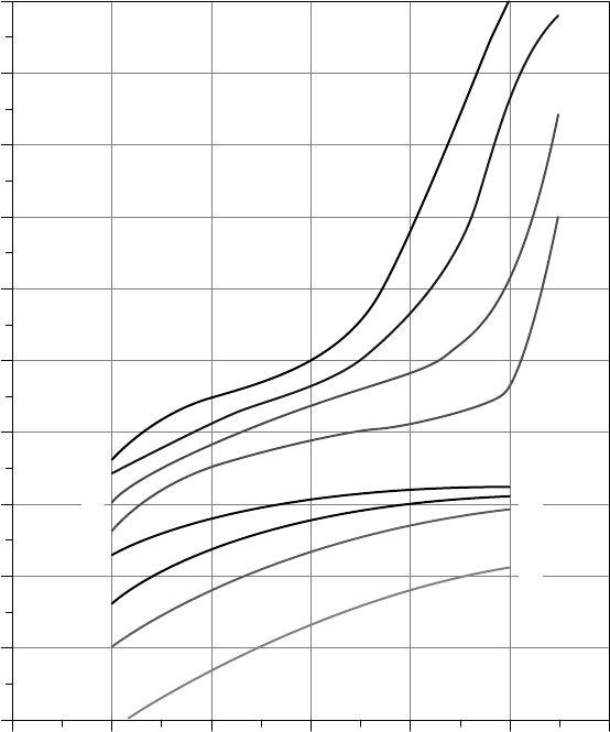
standing of the actual charging and discharging curves for a battery. Figure 9.45
shows representative values of battery voltage for differing charging and dis-
charging currents as a function of SOC.
During charging, notice the sudden rise in cell voltage around the 14-V level as
the battery nears full charge. This is when charging is most inefficient and when
gassing occurs. The release of generated hydrogen and oxygen gases removes
water from the battery, which has to be replaced or the plates may be damaged. It
also creates a potentially dangerous situation since hydrogen gas is so explosive.
In addition, very small quantities of the poisonous gases arsine (AsH
3
) and stibine
(SbH
3
) can be released when hydrogen comes in contact with the lead alloys
arsenic and antimony. Proper ventilation is clearly an important consideration in
the design of a safe battery storage system.
To reduce the need for water replacement, some lead-acid batteries now use
pressure-relief valves that allow most of the oxygen formed during overcharging
to recombine with lead rather than being released. Hydrogen gas releases are
also suppressed. While they do open as necessary to relieve the pressure built up
by hydrogen and oxygen gases, these valve-regulated lead-acid batteries (VRLA)
can reduce gas emissions by over 95% (Linden, 1995).
Gassing and charging losses can be minimized, by using a c harge controller
that has been designed to slow the charging rate as the battery approaches its fully
charged condition. Charge controllers also protect batteries from overcharging by
completely disconnecting the PV array at some predetermined battery voltage,
usually around 14 V (for a 12-V battery). They also keep the batteries from being
overly discharged by disconnecting the load when battery voltage drops below
another set point, usually around 11.5 V.
9.5.7 Battery Sizing
If good weather could be counted on, battery sizing might mean simply providing
enough storage to carry the load through the night and into the next day until
STAND-ALONE PV SYSTEMS 569
120100806040200
11.0
11.5
12.0
12.5
13.0
13.5
14.0
14.5
15.0
15.5
16.0
Battery State of Charge (%)
Battery Voltage (V)
C
/5
C
/10
C
/20
C
/100
C
/5
C
/10
C
/20
C
/40
DISCHARGING
CHARGING
Figure 9.45 Terminal voltage and state of charge for 12-V lead-acid batteries for various
rates of charging and discharging. Based on Sandia National Laboratories (1991).
the sun picks up the load once again. The usual case, of course, is one in which
there are periods of time when little or no sunlight is available and the batteries
might have to be relied on to carry the load for some number of days. During
those periods, there may be some flexibility in the strategy to be taken. Some
noncritical loads, for example, might be reduced or eliminated; and if a generator
is part of the system, a trade-off between battery storage and generator run times
will be part of the design.
Given the statistical nature of weather and the variability of responses to
inclement conditions, there are no set rules about how best to size battery storage.
The key trade-off will be cost. Sizing a storage system to meet the demand
99% of the time can easily cost triple that of one that meets demand only 95%
570 PHOTOVOLTAIC SYSTEMS
8765432
0
2
4
6
8
10
12
14
16
Peak Sun Hours
Days of Usable Storage
99% Availability
95% Availability
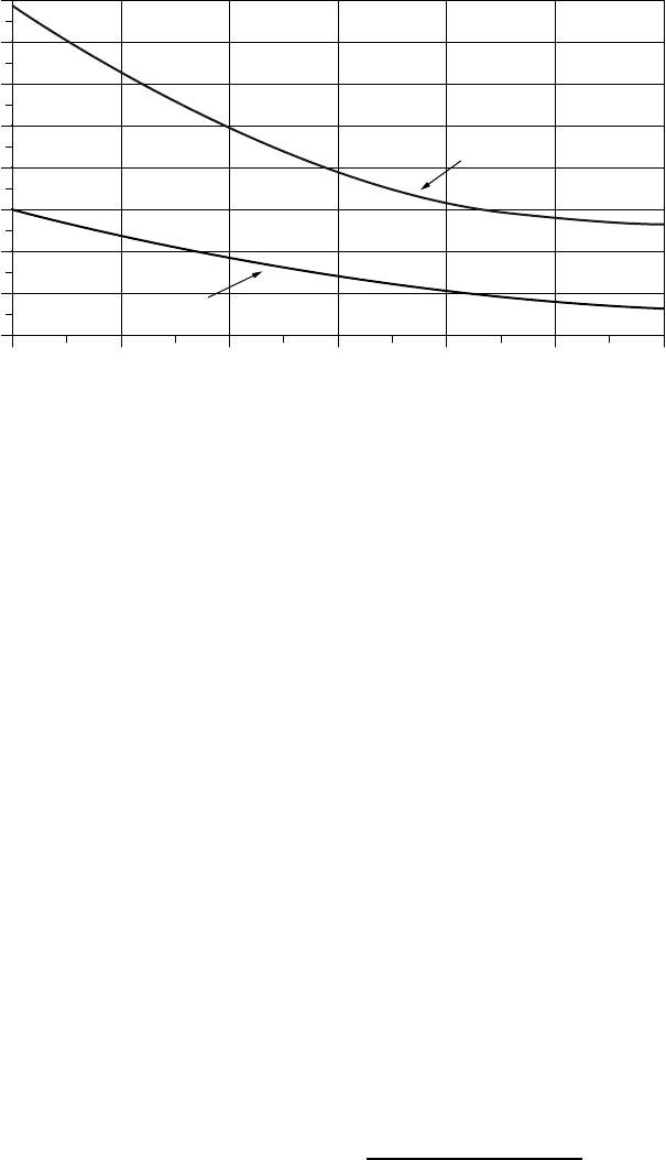
Figure 9.46 Days of battery storage needed for a stand-alone system with 95% and 99%
system availability. Peak sun hours are for the worst month of the year and availability
is on an annual basis. Based on Sandia National Laboratories (1995).
of the time. As a starting point for estimating the number of days of storage
to be provided, consider Fig. 9.46, which is based on the excellent guidebook
Stand-Alone Photovoltaic Systems Handbook of Recommended Design Practices
(Sandia National Laboratories, 1995). The graph gives an estimate for days of
battery storage needed to supply a load as a function of the peak sun hours
per day in the design month, which is the month with the worst combination of
insolation and load. To account for a range of load criticality, two curves are
given: one for loads that must be satisfied during 99% of the 8760 h in a year
and one for less critical loads, for which a 95% system availability is satisfactory.
When doing designs with a computer, it is handy to have equations for the
curves given in Fig. 9.46. The following match pretty well.
Storage days (99%) ≈ 24.0 − 4.73 (Peak sun hours)
+ 0.3 (Peak sun hours)
2
(9.30)
Storage days (95%) ≈ 9.43 − 1.9 (Peak sun hours)
+ 0.11 (Peak sun hours)
2
(9.31)
Figure 9.46 refers to days of “usable storage,” which means after accounting for
impacts associated with maximum allowable battery discharge, Coulomb effi-
ciency, battery temperature, and discharge rate. The relationship between usable
storage and nominal, rated storage (at C/20, 25
◦
C) is given by
Nominal (C/20, 25
◦
C) battery capacity =
Usable battery capacity
(MDOD)(T, DR)
(9.32)
STAND-ALONE PV SYSTEMS 571
where MDOD stands for maximum depth of discharge (default: 0.8 for lead-acid,
deep-discharge batteries, 0.25 for auto SLI; subject to freeze constraints given in
Fig. 9.39) and T, DR stands for temperature and discharge-rate factor (Fig. 9.42).
The following example illustrates the process.
Example 9.18 Battery Sizing for an Off-Grid Cabin. A cabin near Salt Lake
City, Utah, has an ac demand of 3000 Wh/day in the winter months. A decision
has been made to size the batteries such that a 95% system availability will be
provided, and a back-up generator will be kept in reserve to cover the other 5%.
The batteries will be kept in a ventilated shed whose temperature may reach as
low as −10
◦
C. The system voltage is to be 24 V, and an inverter with overall
efficiency of 85% will be used.
Solution. With an 85% efficient inverter, the dc load is
DC load =
AC load
Inverter efficiency
=
3000 Wh/day
0.85
= 3529 Wh/day
With a 24-V system voltage the batteries need to supply
Load =
3529 Wh/day
24 V
= 147 Ah/day @ 24 V
From Appendix E the following monthly insolation data are found for Salt
Lake City:
Tilt Jan Feb Mar Apr May Jun July Aug Sept Oct Nov Dec Year
Lat − 15 2.9 4.0 5.0 5.9 6.6 7.2 7.3 7.0 6.3 5.0 3.3 2.5 5.2
Lat 3.2 4.3 5.2 5.8 6.2 6.6 6.7 6.7 6.4 5.4 3.7 2.9 5.3
Lat + 15 3.4 4.4 5.1 5.4 5.5 5.6 5.8 6.1 6.1 5.5 3.9 3.1 5.0
Even though annual insolation is highest for a tilt angle equal to the local latitude,
we’ll use an L + 15 tilt to help meet winter needs. December has the lowest
insolation so that will be our design month. From Fig. 9.46 at 95% availability
and 3.1 peak sun hours in December, it looks like we need about 4.6 days
of storage.
Usable storage = 147 Ah/day × 4.6day= 676 Ah
We’ll pick deep discharge lead-acid batteries that can be routinely discharged
by 80%. But, we need to check to see whether that depth of discharge will
expose the batteries to a potential freeze problem. From Fig. 9.39, at −10
◦
Cthe
572 PHOTOVOLTAIC SYSTEMS
batteries could be discharged to over 95% without freezing the electrolyte, so an
80% discharge is acceptable.
Batteries that are nominally rated at C/20 and 25
◦
C will be operated in much
colder conditions which degrades storage capacity, but they will be discharged
at a much slower rate, which increases capacity. Figure 9.42 suggests that at
−10
◦
CandaC/72 rate (the 5-day rate for the cabin is even slower, so this is
conservative), storage capacity would be about 0.97 times the nominal capacity.
Applying the 0.80 factor for maximum discharge and the 0.97 factor for dis-
charge rate and temperature in (9.32) gives
Nominal (C/20, 25
◦
C) battery capacity =
676 Ah
0.80 × 0.97
= 871 Ah (at 24 V)
Table 9.15 can help us pick a battery. None of those batteries comes close to
providing that many Ah, so we’re going to have to have parallel strings.
Partly to keep the weight of each battery low enough to be able to handle,
and partly to keep the number of batteries under control, suppose we choose the
Trojan 6 V, 225 Ah, T-105. Three parallel strings would give us 675 Ah, four
would give 900 Ah, and our goal is 871 Ah. Suppose we slightly oversize with
four strings.
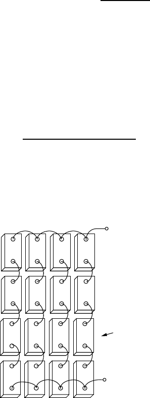
To get 24 V, we need each string to have four batteries, so the total battery
bank will have four parallel strings of four batteries each as shown in Fig. 9.47.
9.5.8 Blocking Diodes
The simplest PV–battery system consists of just a single module connected to
a battery and a load, with no charge controller, inverter, or anything else to
+
−
+
−
+
−
+
−
24 V
900 Ah
6 V, 225 Ah ea.
Figure 9.47 The 24-V, 900-Ah battery bank for the cabin in Example 9.18.
STAND-ALONE PV SYSTEMS 573
−
+
++
−
dc
Load
dc
Load
Ah/d to
battery
Ah/d to
load
+
−
++
−
Blocking
diode
(a)
(b)
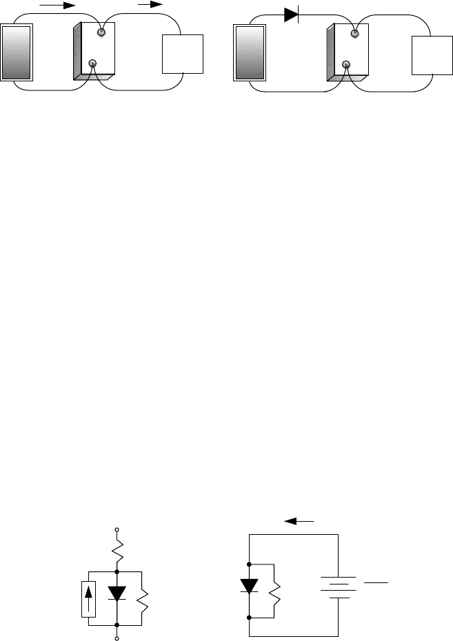
Figure 9.48 Simplest PV–battery system (a). Adding a blocking diode to prevent losses
from the battery through the PV at night (b).
complicate things (Fig. 9.48a). Such a system might provide someone with a bit
of light at night and maybe a few other simple amenities. As long as the user is
careful about not letting the batteries discharge too deeply, or be overcharged, the
system will perform well. There is another concern, however. The system shown
in Fig. 9.48a allows the battery to leak current back through the PV module
at night, which raises the question of whether it might be worthwhile to add a
blocking diode as shown in Fig. 9.48b to prevent that nightly discharge.
The equivalent circuit of a single PV cell shown in Fig. 9.49a will help us
analyze the potential nighttime battery loss problem. Remember that the black-
ened symbol for a diode means that it is a real diode, rather than an ideal one.
Ignoring the insignificant impact of the very small series resistance and elimi-
nating the ideal current source I
SC
because the cell is in the dark at night leaves
the simple circuit of Fig. 9.49b.
Current through the diode in the equivalent circuit for a cell (at 25
◦
C) is given
by the Shockley equation introduced in Chapter 8:
I
d
= I
0
(e
38.9V
d
− 1)(9.33)
R
S
R
P
I
SC
I
B
V
d
V
B
(a)
R
P
+
−
n-cells
(b)
Figure 9.49 Nighttime leakage from a battery back through a PV module with n cells.
(a) Equivalent circuit of one PV cell. (b) A simplified equivalent circuit at night for one
cell having V
B
/n volts from the battery across it.

574 PHOTOVOLTAIC SYSTEMS
The nighttime current from the battery through each cell will be
I
B
= I
d
+ I
R
P
= I
0
(e
38.9V
d
− 1) +
V
d
R
p
(9.34)
where the voltage V
d
across the diode will be equal to the battery voltage V
B
divided by the number of cells n in the PV module.
With this simple nighttime equivalent circuit, we can decide how much leakage
will occur from the battery through the PVs. The following example shows how
to evaluate the potential advantage of using a blocking diode to prevent that
current from flowing.
Example 9.19 Impact of a Blocking Diode to Control Nighttime Battery
Leakage. A PV module is made up of 36 cells, each having a reverse saturation
current I
0
of 1 × 10
−10
A and a parallel resistance of 8 . The PVs provide the
equivalent of 5 A for 6 h each day. The module is connected without a blocking
diode to a battery with voltage 12.5 V.
a. How many Ah will be discharged from the battery over a 15-h night?
b. How much energy will be lost due to this discharge?
c. If a blocking diode is added, how much energy will be dissipated through
the diode during the daytime. Assume the diode while conducting has a
voltage drop of 0.6 V.
Solution. The voltage across each PV cell will be about 12.5 V/36 cells =
0.347 V. From (9.34) the current discharged from the battery while the PV is in
the dark will be
I
B
= 10
−10
(e
38.9×0.347
− 1) +
0.347
8
= 0.000073 + 0.043 = 0.043 A = 43 mA
a. Over a 15-h nighttime period, the loss in Ah from the battery will be
Nighttime loss = 0.043 A ×15 h = 0.65 Ah
b. At a nominal 12.5 V, the energy loss at night will be
Nighttime loss = 0.65 Ah ×12.5V= 8.1Wh
c. During the day the PVs will deliver
PV output = 6h× 5A= 30 Ah

STAND-ALONE PV SYSTEMS 575
The nighttime loss without a blocking diode is 0.65 Ah/30 Ah = 0.02; that
is, 2% of the daytime gains.
With the blocking diode dropping 0.6 V, the daytime loss caused by that
diode is
Blocking diode loss = 30 Ah × 0.6V= 18 Wh
In the example just presented, the blocking diode loses more energy during the
day while it is conducting (18 Wh) than it saves overnight (8.1 Wh). Another
way to look at it is that without a blocking diode, only about 2% of the Ah
of daytime solar gains are lost overnight. In spite of these arguments, blocking
diodes still make some sense. Since the operating point of the battery–P V system
is generally some distance to the left of the knee of the I –V curve, shifting
the battery I –V curve approximately 0.6 V to the right to cover the diode drop
barely changes current delivered by the PVs. That is, in terms of amp-hours, the
diode doesn’t lose any during battery charging, but does stop nighttime battery
discharge, so in terms of amp-hours it does offer a modest net benefit.
9.5.9 Sizing the PV Array
Designing stand-alone PV–battery systems is clearly much more demanding
than sizing grid-connected systems. Month-by-month load estimates and solar
resource evaluations, making trade-offs between ac and dc loads, choosing a sys-
tem voltage, and determining battery storage with or without a back-up generator
are things that simply don’t apply to grid-connected systems. Having addressed
those topics, we can now deal with the most important part of the system: the
PV array itself.
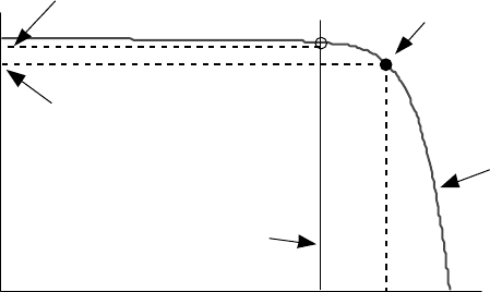
In Fig. 9.50 a 1-sun, PV I –V curve has been drawn along with a vertical
I –V line for a battery. As shown, during battery charging, the operating point of
the PVs is almost always above the knee of the PV I –V curve, which means that
charging current will exceed the rated current of the PVs. It is a fairly conservative
estimate therefore to simply use the rated current of the PVs as an indication of the
battery charging current at 1-sun insolation. There are circumstances in which
this assumption should be checked—as, for example, when a 12-V battery is
charged in a high-temperature environment with a “self-regulating” PV module
having fewer than the usual 36 cells in series. Fewer cells and higher temperatures
move the maximum power point (MPP) toward the battery I –V curve, and the
conservatism of the assumption decreases.
Our simple sizing procedure will be based on the same “peak hours” approach
used for grid-connected systems, except that it will be applied to current rather
than power. So, for example, an area with 6 kWh/m
2
-day of insolation is treated
as if it has 6 h/day of 1-sun, 1-kW/m
2
radiation. Then using the rated current
I
R
at 1-sun, times peak hours of sun, gives us amp-hours of current provided to
the batteries.
576 PHOTOVOLTAIC SYSTEMS
Voltage
Current
Rated current
I
R
Maximum
Power Point
Battery current
I
B
V
B
V
R
Battery
I
−
V
Curve
"1-sun"
PV
I
−
V
Curve
Figure 9.50 Estimating battery charging at 1-sun to be the rated current of the PVs is a
fairly conservative assumption.
Notice that the operating point for battery charging is usually some distance
away from the MPP. This means that a considerable fraction of power that the
PVs could provide based on the rated power P
R
of the module is not being
delivered to the batteries. It would not be appropriate, therefore, to multiply the
peak hours of sunlight times the rated power of the module to estimate energy to
the batteries.
The product of rated current I
R
times peak hours of insolation provides a good
starting-point estimate for Ah delivered to the batteries. It is common practice
to apply a de-rating of about 10% to account for dirt and gradual aging of the
modules. The temperature and module-mismatch factors that were quite important
for grid-connected systems with MPP trackers are usually ignored for PV–battery
systems. This is because the operating point for battery systems is far enough
away from the knee of the I –V curve that those variations are minimum and are
to some extent offset by the conservatism associated with assuming that charging
current is only I
R
.
Here is another important feature of stand-alone PV sizing. It will be based
on (a) amp-hours from the PVs into the batteries and (b) amp-hours from the
batteries to the load. That is, the appropriate battery efficiency measure will be
the Coulomb efficiency. The current delivered to the batteries needs to multiplied
by the Coulomb efficiency (Ah
out
/Ah
in
) to give Ah delivered from the batteries
to the load:
Ah to load = I
R
× Peak sun hours × Coulomb efficiency × De-rating factor
(9.35)
The only other thing to keep track of is the system voltage. For a 12-V system
voltage and 12-V modules, modules are added in parallel until sufficient Ah are
provided for the load. For a 24-V system voltage and 12-V modules, two modules
in series are needed to provide the 24 V, and then parallel strings of two series

STAND-ALONE PV SYSTEMS 577
modules each are added to deliver the Ah needed by the load. Or, if 24 V is
the system voltage, it may make more sense to simply choose 24-V PV modules
rather than using two 12-V versions.
Example 9.20 PVs for the Cabin in Salt Lake City. The cabin from Example
9.18 needs 3000 Wh/day of ac delivered from an 85%-efficient inverter. For a
24-V system voltage, a 90% Coulomb efficiency, and 10% de-rating (de-rating
factor = 0.90), size a PV array using Kyocera KC120 modules.
Solution. From Table 9.3, the Kyocera KC120 is a 120-W module with its
maximum power point at a current of 7.1 A and a voltage of 16.9 V. From
Example 9.18, the worst solar month is December, with 3.1 peak hours of sun-
light at a tilt of L + 15. Using (9.35), one string of modules will therefore deliver
in December about
Ah to inverter = 7.1A× 3.1h/day× 0.90 × 0.90 = 17.83 Ah/day per string
For an 85% efficient inverter to deliver 3000 Wh/day of 120 V ac, it needs a
24-V dc input of
Inverter dc input =
3000 Wh/day
0.85 × 24 V
= 147 Ah/day @ 24 V
Since these modules have a rated voltage of 16.9 V, they are nominally “12-V
modules.” Therefore two modules are needed in series to provide a single 24-
V string.
The number of parallel strings of modules needed is
Number of parallel strings =
147 Ah/day
17.83 Ah/day-string
= 8.25 strings
Suppose that we undersize it slightly and use eight parallel strings with two
modules per string, for a total of 16 modules.
Including the 0.90 de-rating factor, the PVs will deliver
PV output = 8 strings × 7.1 A/string × 3.1h/day× 0.90
= 158 Ah/day @ 24 Vdc
The batteries with 0.90 Coulomb efficiency will deliver
Battery output = 158 Ah/day × 0.90 = 142 Ah/day @ 24 Vdc