Masters G.M. Renewable and Efficient Electric Power Systems
Подождите немного. Документ загружается.


38 BASIC ELECTRIC AND MAGNETIC CIRCUITS
and
e
2
= N
2
dφ
dt
(1.52)
Continuing the idealization of the transformer, if there are no wire losses, then
the voltage on the incoming wires, v
1
, is equal to the emf e
1
, and the voltage on
the output wires, v
2
, equals e
2
. Dividing (1.52) by (1.51) gives
v
2
v
1
=
e
2
e
1
=
N
2
(dφ/dt)
N
1
(dφ/dt)
(1.53)
Before canceling out the dφ/dt, note that we can only do so if dφ/dt is not
equal to zero. That is, the following fundamental relationship for transformers
(1.53) is not valid for dc conditions:
v
2
=
N
2
N
1
v
1
= (turns ratio) · v
1
(1.54)
The quantity in the parentheses is called the turns ratio. If voltages are to be
raised, then the turns ratio needs to be greater than 1; to lower voltages it needs
to be less than 1.
Does (1.54), which says that we can easily increase the voltage from primary
to secondary, suggest that we are getting something for nothing? The answer is,
as might be expected, no. While (1.54) suggests an easy way to raise ac voltages,
energy still must be conserved. If we assume that our transformer is perfect; that
is, it has no energy losses of its own, then power going into the transformer on
the primary side, must equal power delivered to the load on the secondary side.
That is,
v
1
i
1
= v
2
i
2
(1.55)
Substituting (1.54) into (1.55) gives
i
2
=
v
1
v
2
i
1
=
N
1
N
2
i
1
(1.56)
What (1.56) shows is that if we increase the voltage on the secondary side
of the transformer (to the load), we correspondingly reduce the current to the
load. For example, bumping the voltage up by a factor of 10 reduces the current
delivered by a factor of 10. On the other hand, decreasing the voltage by a factor
of 10 increases the current 10-fold on the secondary side.
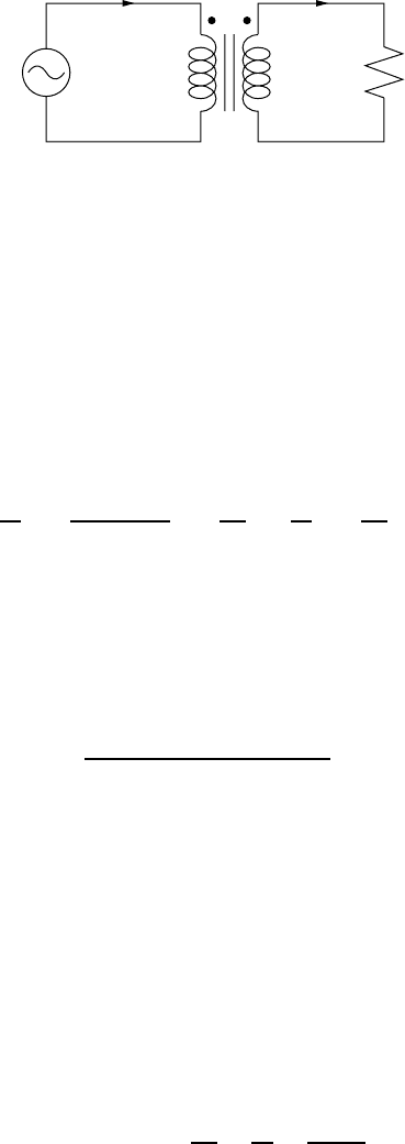
Another important consideration in transformer analysis is what a voltage
source “sees” when it sends current into a transformer that is driving a load.
For example, in Fig. 1.28 a voltage source, transformer, and resistive load are
shown. The symbol for a transformer shows a couple of parallel bars between
the windings, which is meant to signify that the coil is wound around a metal
(steel) core (not an air core). The dots above the windings indicate the polarity
TRANSFORMERS 39
i
1
N
1
N
2
R
i
2
v
2
+
−
+
−
v
1
Figure 1.28 A resistance load being driven by a voltage source through a transformer.
of the windings. When both dots are on the same side (as in Fig. 1.28) a positive
voltage on the primary produces a positive voltage on the secondary.
Back to the question of the equivalent load seen by the input voltage source
for the circuit of Fig. 1.28. If we call that load R
in
,thenwehave
v
1
= R
in
i
1
(1.57)
Rearranging (1.57) and substituting in (1.55) and (1.56) gives
R
in
=
v
1
i
1
=
(N
1
/N
2
)v
2
(N
2
/N
1
)i
2
=
N
1
N
2
2
·
v
2
i
2
=
N
1
N
2
2
R(1.58)
where v
2
/i
2
= R is the resistance of the transformer load.
As far as the input voltage source is concerned, the load it sees is the resistance
on the secondary side of the transformer divided by the square of the turns ratio.
This is referred to as a resistance transformation (or more generally an impedance
transformation).
Example 1.11 Some Transformer Calculations. A 120- to 240-V step-up
transformer is connected to a 100- load.
a. What is the turns ratio?
b. What resistance does the 120-V source see?
c. What is the current on the primary side and on the secondary side?
Solution
a. The turns ratio is the ratio of the secondary voltage to the primary voltage,
Turns ratio =
N
2
N
1
=
v
2
v
1
=
240 V
120 V
= 2
40 BASIC ELECTRIC AND MAGNETIC CIRCUITS
b. The resistance seen by the 120 V source is given by (1.58):
R
in
=
N
1
N
2
2
R =
1
2
2
100 = 25
c. The primary side current will be
i
primary
=
v
1
R
in
=
120 V
25
= 4.8 A
On the secondary side, current will be
i
secondary
=
v
2
R
load
=
240 V
100
= 2.4 A
Notice that power is conserved:
v
1
· i
1
= 120 V · 4.8 A = 576 W
v
2
· i
2
= 240 V · 2.4 A = 576 W
1.8.2 Magnetization Losses
Up to this point, we have considered a transformer to have no losses of any
sort associated with its performance. We know, however, that real windings have
inherent resistance so that when current flows there will be voltage and power
losses there. There are also losses associated with the magnetization of the core,
which will be explored now.
The orientation of atoms in ferromagnetic materials (principally iron, nickel,
and cobalt as well as some rare earth elements) are affected by magnetic fields.
This phenomenon is described in terms of unbalanced spins of electrons, which
causes the atoms to experience a torque, called a magnetic moment, when exposed
to a magnetic field.
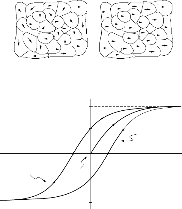
Ferromagnetic metals exist in a crystalline structure with all of the atoms
within a particular portion of the material arranged in a well-organized lattice.
The regions in which the atoms are all perfectly arranged is called a subcrystalline
domain. Within each magnetic domain, all of the atoms have their spin axes
aligned with each other. Adjacent domains, however, may have their spin axes
aligned differently. The net effect of the random orientation of domains in an
unmagnetized ferromagnetic material is that all of the magnetic moments cancel
each other and there is no net magnetization. This is illustrated in Fig. 1.29a.
When a strong magnetic field H is imposed on the domains, their spin axes
begin to align with the imposed field, eventually reaching saturation as shown in
Fig. 1.29b. After saturation is reached, increasing the magnetizing force causes no
increase in flux density, B. This suggests that the relationship between magnetic
TRANSFORMERS 41
(a) (b)
Figure 1.29 Representation of the domains in (a) an unmagnetized ferromagnetic mate-
rial and (b) one that is fully magnetized.
a
d
0c
b
H
increasing
H
decreasing
Remanent flux
B
r
Coercive flux −
H
c
Start from
B
= 0
H
−
B
r
−
B
sat
B
sat
e
H
c
Figure 1.30 Cycling an imposed mmf on a ferromagnetic material produces a hystere-
sis loop.
field H and flux density B will not be linear, as was implied in (1.35), and
in fact will exhibit some sort of s-shaped behavior. That is, permeability µ is
not constant.
Figure 1.30 illustrates the impact that the imposition of a magnetic field H on
a ferromagnetic material has on the resulting magnetic flux density B.Thefield
causes the magnetic moments in each of the domains to begin to align. When the
magnetizing force H is eliminated, the domains relax, but don’t return to their
original random orientation, leaving a remanent flux B
r
; that is, the material
becomes a “permanent magnet.” One way to demagnetize the material is to heat
it to a high enough temperature (called the Curie temperature) that the domains
once again take on their random orientation. For iron, the Curie temperature is
770
◦
C.
42 BASIC ELECTRIC AND MAGNETIC CIRCUITS
Consider what happens to the B –H curve as the magnetic domains are cycled
back and forth by an imposed ac magnetomagnetic force. On the B –H curve
of Fig 1.30, the cycling is represented by the path o–a followed by the path
a–b. If the field is driven somewhat negative, the flux density can be brought
back to zero (point c) by imposing a coercive force, H
c
; forcing the applied mmf
even more negative brings us to point d. Driving the mmf back in the positive
direction takes us along path d–e–a.
The phenomenon illustrated in the B –H curve is called hysteresis. Cycling
a magnetic material causes the material to heat up; in other words, energy is
being wasted. It can be shown that the energy dissipated as heat in each cycle is
proportional to the area contained within the hysteresis loop. Each cycle through
the loop creates an energy loss; therefore the rate at which energy is lost, which
is power, is proportional to the frequency of cycling and the area within the
hysteresis loop. That is, we can write an equation of the sort
Power loss due to hysteresis = k
1
f(1.59)
where k
1
is just a constant of proportionality and f is the frequency.
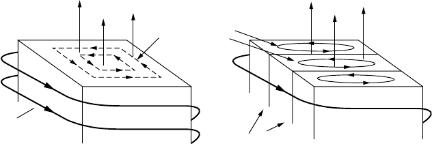
Another source of core losses is caused by small currents, called eddy currents,
that are formed within the ferromagnetic material as it is cycled. Consider a cross
section of core with magnetic flux φ aligned along its axis as shown in Fig. 1.31a.
We know from Faraday’s law that anytime a loop of electrical conductor has
varying magnetic flux passing through it, there will be a voltage (emf) created
in that loop proportional to the rate of change of φ. That emf can create its own
current in the loop. In the case of our core, the ferromagnetic material is the
conductor, which we can think of as forming loops of conductor wrapped around
flux creating the eddy currents shown in the figure.
To analyze the losses associated with eddy currents, imagine the flux as a
sinusoidal, time-varying function
φ = sin(ωt) (1.60)
Eddy currents
Flux f
Flux f
Laminations
(a) (b)
Core windings
i
Figure 1.31 Eddy currents in a ferromagnetic core result from changes in flux link-
ages: (a) A solid core produces large eddy current losses. (b) Laminating the core yields
smaller losses.

TRANSFORMERS 43
The emf created by changing flux is proportional to dφ/dt
e = k
2
dφ
dt
= k
2
ω cos(ωt) (1.61)
where k
2
is just a constant of proportionality. The power loss in a conduct-
ing “loop” around this changing flux is proportional to voltage squared over
loop resistance:
Eddy current power loss =
e
2
R
=
1
R
[k
2
ω cos(ωt)]
2
(1.62)
Equation (1.62) suggests that power loss due to eddy currents is inversely pro-
portional to the resistance of the “loop” through which the current is flowing. To
control power losses, therefore, there are two approaches: (1) Increase the elec-
trical resistance of the core material, and (2) make the loops smaller and tighter.
Tighter loops have more resistance (since resistance is inversely proportional to
cross-sectional area through which current flows) and they contain less flux φ
(emf is proportional to the rate of change of flux, not flux density).
Real transformer cores are designed to control both causes of eddy current
losses. Steel cores, for example, are alloyed with silicon to increase resistance;
otherwise, high-resistance magnetic ceramics, called ferrites, are used instead of
conventional alloys. To make the loops smaller, cores are usually made up of
many thin, insulated, lamination layers as shown in Fig. 1.31b.
The second, very important conclusion from Eq. (1.62) is that eddy current
losses are proportional to frequency squared:
Power loss due to eddy currents = k
3
f
2
(1.63)
Later, when we consider harmonics in power circuits, we will see that some
loads cause currents consisting of multiples of the fundamental 60-Hz frequency.
The higher-frequency harmonics can lead to transformer core burnouts due to the
eddy current dependence on frequency squared.
Transformer hysteresis losses are controlled by using materials with minimal
B –H hysteresis loop area. Eddy current losses are controlled by picking core
materials that have high resistivity and then laminating the core with thin, insu-
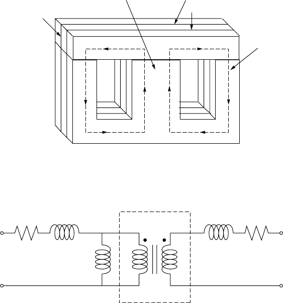
lated sheets of material. Leakage flux losses are minimized not only by picking
materials with high permeability but also by winding the primary and secondary
windings right on top of each other. A common core configuration designed
for overlapping windings is shown in Fig. 1.32. The two windings are wrapped
around the center section of core while the outer two sections carry the flux in
closed loops. The top of a laminated slice of this core is a separate piece in
order to facilitate wrapping the windings around core material. With the top off,
a mechanical winder can easily wrap the core, after which the top bar is attached.
A real transformer can be modeled using a circuit consisting of an idealized
transformer with added idealized resistances and inductors as shown in Fig. 1.33.
44 BASIC ELECTRIC AND MAGNETIC CIRCUITS
Both windings
wrapped around
central core
Laminated core to
reduce eddy
currents
Flux
lines
Removable
top pieces
to facilitate
winding
Figure 1.32 A type “E-1” laminated core for a transformer showing the laminations and
the removable top pieces to enable machine winding. Windings are wound on top of each
other on the central portion of the core.
Ideal transformer
R
1
N
1
N
2
L
1
L
2
R
2
V
1
V
2
L
m
Figure 1.33 A model of a real transformer accounts for winding resistances, leakage
fluxes, and magnetizing inductance.
Resistors R
1
and R
2
represent the resistances of the primary and secondary wind-
ings. L
1
and L
2
represent the inductances associated with primary and secondary
leakage fluxes that pass through air instead of core material. Inductance L
m
,
the magnetizing inductance, allows the model to show current in the primary
windings even if the secondary is an open circuit with no current flowing.
PROBLEMS
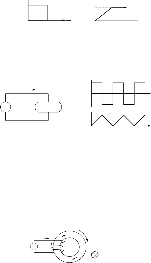
1.1. Either a resistor, capacitor or inductor is connected through a switch to a
current source. At t = 0, the switch is closed and the following applied
current results in the voltage shown. What is the circuit element and what
is its magnitude?
PROBLEMS 45
Volts
100
010
Amps
0.10
time (s) time (s)
010
Figure P1.1
1.2. A voltage source produces the square wave shown below. The load, which
is either an ideal resistor, capacitor or inductor, draws current current as
shown below.
t
t
0
1
−1
1
Load
+
−
i
(
t
)
v
(
t
)
i
(
t
)
v
(
t
)
Figure P1.2
a. Is the “Load” a resistor, capacitor or inductor?
b. Sketch the power delivered to the load versus time.
c. What is the average power delivered to the load?
1.3. A single conductor in a transmission line dissipates 6,000 kWh of energy
over a 24-hour period during which time the current in the conductor was
100 amps. What is the resistance of the conductor?
1.4. A core-and-coil inductor has a mean cross-sectional area of 0.004 m
2
and
a mean circumference of 0.24 m. The iron core has a relative permeability
of 20,000. It is wrapped with 100 turns carrying 1 amp of current.
1 A
100
turns
v
+
+
−
−
0.004 m
2
0.24 m
e
f
Figure P1.4
a. What is the reluctance of the core R (A-t/Wb)?
b. What is the inductance of the core and coil L (henries)?
c. What is the magnetic field intensity H (A-t/m)?
d. What is the magnetic flux density B (Wb/m
2
)
46 BASIC ELECTRIC AND MAGNETIC CIRCUITS
1.5. The resistance of copper wire increases with temperature in an approxi-
mately linear manner that can be expressed as
R
T 2
= R
T 1
[1 + α(T
2
− T
1
)]
where α = 0.00393/
◦
C. Assuming the temperature of a copper transmission
line is the same as the ambient temperature, how hot does the weather have
to get to cause the resistance of a transmission line to increase by 10%
over its value at 20
◦
C?
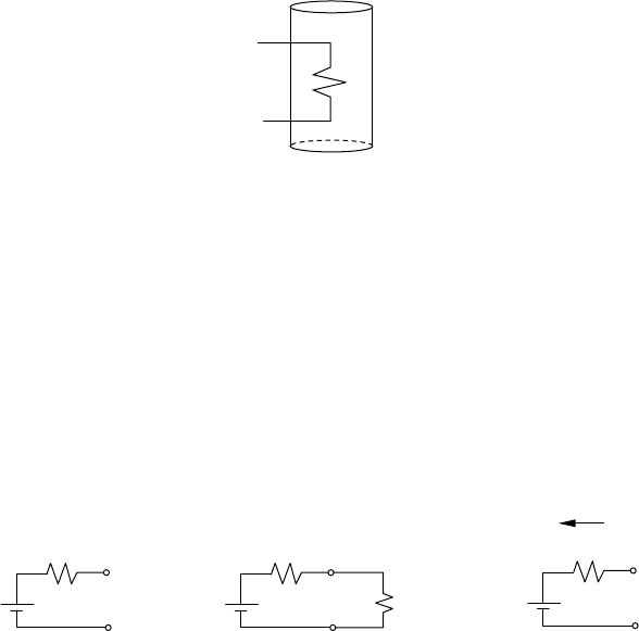
1.6. A 52-gallon electric water heater is designed to deliver 4800 W to an
electric-resistance heating element in the tank when it is supplied with
240 V (it doesn’t matter if this is ac or dc).
240 V
4800 W
52
gal
Figure P1.5
a. What is the resistance of the heating element?
b. How many watts would be delivered if the element is supplied with
208 V instead of 240 V?
c. Neglecting any losses from the tank, how long would it take for 4800 W
to heat the 52 gallons of water from 60
◦
F to 120
◦
F? The conver-
sion between kilowatts of electricity and Btu/hr of heat is given by
3412 Btu/hr = 1 kW. Also, one Btu heats 1 lb of water by 1
◦
Fand1
gallon of water weighs 8.34 lbs.
1.7. Suppose an automobile battery is modeled as an ideal 12-V battery in series
with an internal resistance of 0.01 as shown in (a) below.
(a) Battery model
(b) Driving a 0.03 Ω starter motor
(c) Being charged
+
0.01 Ω
12 V
0.03 Ω
V
b
+
0.01 Ω
12 V
20 A
V
b
12 V
+
0.01 Ω
V
b
Figure P1.7
a. What current will be delivered when the battery powers a 0.03 starter
motor, as in (b)? What will the battery output voltage be?
b. What voltage must be applied to the battery in order to deliver a 20-A
charging current as in (c)?
PROBLEMS 47
1.8. Consider the problem of using a low-voltage system to power a small
cabin. Suppose a 12-V system powers a pair of 100-W lightbulbs (wired
in parallel).
a. What would be the (filament) resistance of a bulb designed to use 100 W
when it receives 12 V?
b. What would be the current drawn by two such bulbs if each receives a
full 12 V?
c. What gage wire should be used if it is the minimum size that will carry
the current.
d. Suppose a 12-V battery located 80-ft away supplies current to the pair
of bulbs through the wire you picked in (c). Find:
1. The equivalent resistance of the two bulbs plus the wire resistance
to and from the battery.
2. Current delivered by the battery
3. The actual voltage across the bulbs
4. The power lost in the wires
5. The power delivered to the bulbs
6. The fraction of the power delivered by the battery that is lost in
the wires.
1.9. Repeat Problem 1.8 using a 60-V system using the same 12 gage wire.
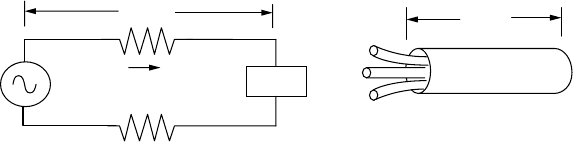
1.10. Suppose the lighting system in a building draws 20 A and the lamps are,
on the average, 100 ft from the electrical panel. Table 1.3 suggests that
12 ga wire meets code, but you want to consider the financial merits of
wiring the circuit with bigger 10 ga wire. Suppose the lights are on 2500
hours per year and electricity costs $0.10 per kWh.
20 A
Lights
100 ft
+
−
n
100 ft
Romex
Figure P1.10
a. Find the energy savings per year (kWhr/yr) that would result from using
10 ga instead of 12 ga wire.
b. Suppose 12 ga wire costs $25 per 100 ft of “Romex” (2 conductors, each
100-ft long, plus a ground wire in a tough insulating sheath) and 10 ga
costs $35 per 100 ft. What would be the “simple payback” period (sim-
ple payback = extra 1st cost/annual $ savings) when utility electricity
costs $0.10/kWh?
c. An effective way to evaluate energy efficiency projects is by calculat-
ing the annual cost associated with conservation and dividing it by the