Masters G.M. Renewable and Efficient Electric Power Systems
Подождите немного. Документ загружается.

58 FUNDAMENTALS OF ELECTRIC POWER
v
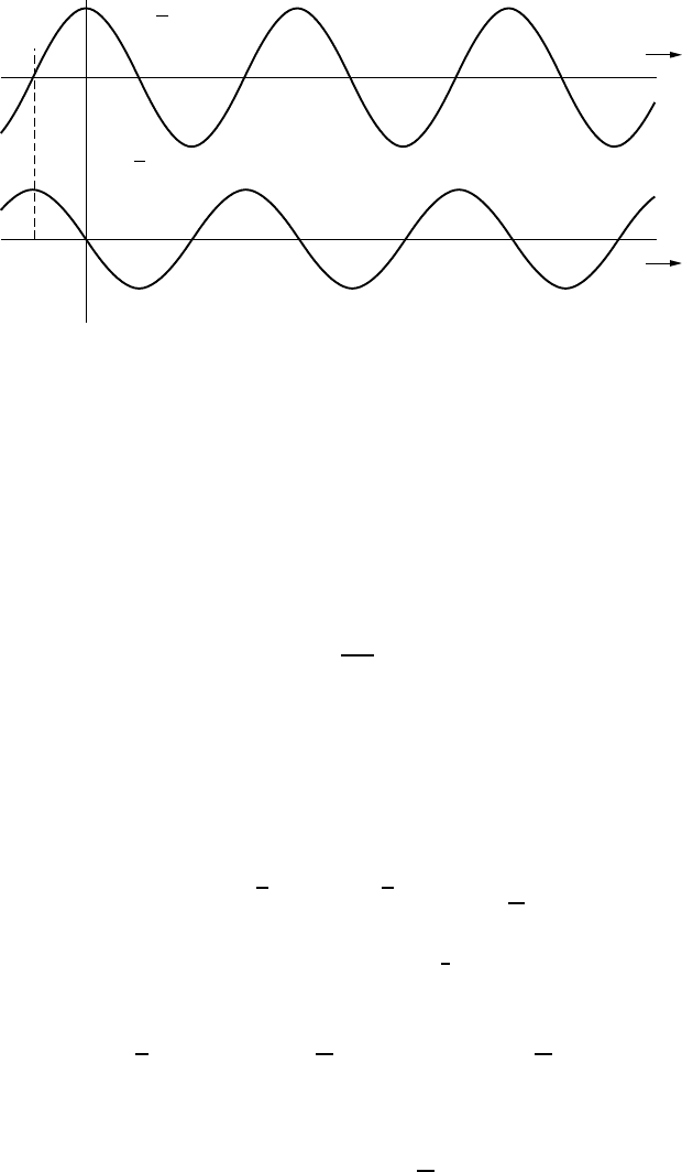
=√2
V
cos w
t
i
=√2w
CV
cos(w
t
+ p/2)
−p/2
w
t
w
t
Figure 2.6 Current through a capacitor leads the voltage applied to it.
which says that the rms current I is given by
I = ωCV (2.22)
and the phase angle between current and voltage is
θ = π/2 (2.23)
Rearranging (2.22) gives
V =
1
ωC
I(2.24)
Equation (2.24) is beginning to look like an ac version of Ohm’s law for capaci-
tors. It should be used with caution, however, since it does not capture the notion
that current and voltage are 90
◦
out of phase with each other.
Also of interest is the average power dissipated by a capacitor subjected to
a sinusoidal voltage. Since instantaneous power is the product of voltage and
current, we can write
p = vi =
√
2V cos ωt ·
√
2I cos
ωt +
π
2
(2.25)
Using the trigonometric identity cos A · cos B =
1
2
[cos(A + B) + cos(A − B)]
gives
p = 2VI ·
1
2
cos
ωt + ωt +
π
2
+ cos
ωt −
ωt +
π
2
(2.26)
Since cos(−π/2) = 0, this simplifies to
p = VI cos
2ωt +
π
2
(2.27)
IDEALIZED COMPONENTS SUBJECTED TO SINUSOIDAL VOLTAGES 59
Since the average value of a sinusoid is zero, (2.27) tells us that the average
power dissipated by a capacitor is zero.
P
avg capacitor
= 0 (2.28)
Some of the time the capacitor is absorbing power (charging) and some of the
time it is delivering power (discharging), but the average power is zero.
Example 2.4 Current in a Capacitor. A 120-V, 60-Hz ac source sends cur-
rent to a 10-microfarad capacitor. Find the rms current flowing and write an
equation for the current as a function of time.
Solution. The rms value of current is given by (2.22) as
I = ωCV = 2π60 ·10 × 10
−6
· 120 = 0.452 A
The phase angle is θ = π /2, so from (2.21) the complete expression for current is
i =
√
2I cos(ωt + θ) =
√
2 · 0.452 cos
2π60t +
π
2
= 0.639 cos
377t +
π
2
2.2.3 Idealized Inductors
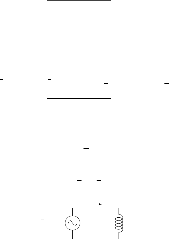
A sinusoidal voltage applied across an inductor is shown in Fig. 2.7.
We want to find the current through the inductor. Starting with the fundamental
relationship for inductors,
v = L
di
dt
(2.29)
and then solving for current:
i =
di =
v
L
dt =
1
L
vdt (2.30)
i
v
=√2
V
cos w
t
L
+
−
Figure 2.7 A sinusoidal voltage across an ideal inductor.

60 FUNDAMENTALS OF ELECTRIC POWER
and inserting the equation for applied voltage
i =
1
L
√
2V cos ωt dt =
√
2V
L
cos ωt dt =
√
2V
ωL
sin ωt (2.31)
Applying the trigonometric relationship sin ωt = cos(ωt − π/2) gives
i =
1
ωL
√
2V cos
ωt −
π
2
=
√
2I cos(ωt + θ) (2.32)
Equation (2.32) tells us that (1) the current through the inductor has the same
frequency ω as the applied voltage, (2) the current lags behind the voltage by
an angle θ =−π /2, and (3) the rms value of current is
I =
1
ωL
V(2.33)
Rearranging (2.33) gives us something that looks like an ac version of Ohm’s
law for inductors:
V = (ωL)I (2.34)
So, for an inductor, you have to supply some voltage before current flows;
for a capacitor, you need to supply current before voltage builds up. One way to
remember which is which, is with the memory aid
“ELI the ICE man”
That is, for an inductor (L), voltage (E, as in emf) comes before current (I),
while for a capacitor C, current (I ) comes before voltage (E).
Finally, let us take a look at the power dissipated by an inductor:
p = vi =
√
2V cos ωt ·
√
2I cos
ωt −
π
2
(2.35)
Using the trigonometric identity for the product of two cosines, gives instanta-
neous power through the inductor
p = 2VI ·
1
2
cos
ωt + ωt −
π
2
+ cos
ωt −
ωt −
π
2
= VI cos
2ωt −
π
2
(2.36)
The average value of (2.36) is zero.
P
avg inductor
= 0 (2.37)
That is, an inductor is analogous to a capacitor in that it absorbs energy while
current is increasing, storing that energy in its magnetic field, then it returns that
POWER FACTOR 61
energy when the current drops and the magnetic field collapses. The net power
dissipated when an inductor is subjected to an ac voltage is zero.
2.3 POWER FACTOR
Those rather tedious derivations for the impact of ac voltages applied to ide-
alized resistors, capacitors, and inductors has led to three simple but important
conclusions. One is that the currents flowing through any of these components
will have the same ac frequency as the source of the voltage that drives the cur-
rent. Another is that there can be a phase shift between current and voltage. And
finally, resistive elements are the only components that dissipate any net energy.
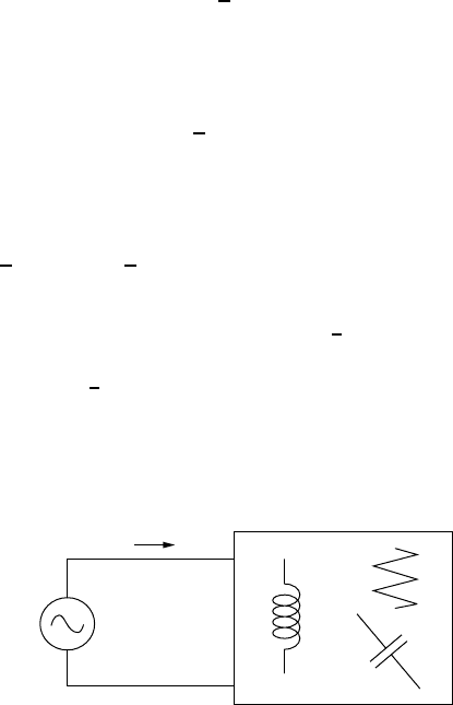
Let us put these ideas together to analyze the generalized black box of Fig. 2.8.
The black box contains any number of idealized resistors, capacitors, and
inductors, wired up any which way. The voltage source driving this box of
components has rms voltage V , and we will arbitrarily assign it a phase angle
of θ = 0.
v =
√
2V cos ωt (2.38)
Since the current delivered to the black box has the same frequency as the voltage
source that drives it, we can write the following generalized current response as
i =
√
2I cos(ωt + θ) (2.39)
The instantaneous power supplied by the voltage source, and dissipated by the
circuit in the box, is
p = vi =
√
2V cos ωt ·
√
2I cos(ωt + θ) = 2VI [cos ωt · cos(ωt + θ)] (2.40)
Once again, applying the identity cos A · cos B =
1
2
[cos(A + B) + cos(A − B)]
gives
p = 2VI
1
2
[cos(ωt + ωt + θ) + cos(ωt − ωt − θ)]
(2.41)
so
p = VI cos(2ωt + θ)+ VI cos(−θ) (2.42)
V
+
−
i
Figure 2.8 A black box of ideal resistors, capacitors, and inductors.

62 FUNDAMENTALS OF ELECTRIC POWER
The average value of the first term in (2.42) is zero, and using cos x = cos(−x)
lets us write that the average power dissipated in the black box is given by
P
avg
= VI cos θ = VI × PF (2.43)
Equation (2.43) is an important result. It says that the average power dissipated
in the box is the product of the rms voltage supplied times the rms current
delivered times the cosine of the angle between the voltage and current. The
quantity cos θ is called the power factor (PF):
Power factor = PF = cos θ(2.44)
The power expressed by (2.43) tells us the rate at which real work can be
done in the black box. That black box, for example, might be a motor, in which
case (2.43) gives us power to the motor in watts.
Why is power factor important? With an “ordinary” watt-hour meter on the
premises, a utility customer pays only for watts of real power used within their fac-
tory, business, or home. The utility, on the other hand, has to cover the i
2
R resistive
power losses in the transmission and distribution wires that bring that power to the
customer. When a customer has voltage and current way out of phase—that is, the
power factor is “poor”—the utility loses more i
2
R power on its side of the meter
than occurs when a customer has a “good” power factor (PF ≈ 1.0).
Example 2.5 Good Versus Poor Power Factor. A utility supplies 12,000 V
(12 kV) to a customer who needs 600 kW of real power. Compare the line losses
for the utility when the customer’s load has a power factor of 0.5 versus a power
factor of 1.0.
Solution. To find the current drawn when the power factor is 0.5, we can start
with (2.43):
P = VI · PF
600 kW = 12 kV · I(A) · 0.5
so
I =
600
12 × 0.5
= 100 A
When the power factor is improved to 1.0, (2.43) now looks like
600 kW = 12 kV · I(A) · 1.0
so the current needed will be I =
600
12
= 50 A
THE POWER TRIANGLE AND POWER FACTOR CORRECTION 63
When the power factor in the plant is improved from 0.5 to 1.0, the amount
of current needed to do the same work in the factory is cut in half. The utility
line losses are proportional to current squared, so line losses for this customer
have been cut to one-fourth of their original value.
2.4 THE POWER TRIANGLE AND POWER FACTOR CORRECTION
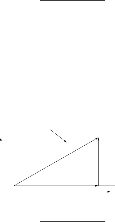
Equation (2.43) sets up an important concept, called the power triangle.The
actual power consumed by a circuit is the rate at which real work can be done
(in watts). Because voltage V and current I may not be in phase, their product
does not, in general, equal real power. Figure 2.9 sets up a power triangle in
which the hypotenuse is the product of rms volts times rms amps. This leg is
called the apparent power, S, and it has units of volt-amps (VA). Those volt-amps
are resolved into the horizontal component P = VI cos θ,whichisreal power in
watts. The vertical side of the triangle, Q = VI sin θ, is called reactive power and
has units of VAR (which stands for volt-amps-reactive). Reactive VAR power is
incapable of doing any work: It corresponds to voltage 90
◦
out of phase with
current so any work absorbed in one half of the cycle is returned, unchanged, in
the other half.
Apparent power,
S
=
VI
volt-amps
Real power,
P
(watts)
Q
=
VI
sin q
Volt-Amps-Reactive (VAR)
Reactive
power,
Q
(VAR)
P
=
VI
cos q
q
Figure 2.9 Showing apparent power S (volt-amps) resolved into reactive power (VAR)
and real power P (watts).
Example 2.6 Power Triangle for a Motor. A 230-V induction motor draws
25 A of current while delivering 3700 W of power to its shaft. Draw its power
triangle.
Solution
Real power P = 3700 W = 3.70 kW
Apparent power S = 25 A × 230 V = 5750 volt-amps = 5.75 kVA
64 FUNDAMENTALS OF ELECTRIC POWER
Power factor PF =
Real power
Apparent power
=
3700 W
5750 VA
= 0.6435
Phase angle θ = cos
−1
(0.6435) = 50
◦
Reactive power Q = S sin θ = 5750 sin 50
◦
= 4400 VAR = 4.40 kVAR
The power triangle is therefore
q = 50°
Real power
P
= 3.70 kW
Reactive power
Q
= 4.40 kVAR
Apparent power
S
= 5.75 kVA
Utilities are very concerned about customers who draw a lot of reactive
power—that is, customers with poor power factors. As suggested in Example 2.5,
reactive power increases line losses for the utility, but doesn’t result in any more
kilowatt-hours (kWh) of energy sales to the customer. To discourage large cus-
tomers from having a poor power factor, utilities will charge a penalty based on
how low the power factor is, or they will charge not only for kWh of energy but
also for kVAR of reactive power.
Many large customers have loads that are dominated by electric motors, which
are highly inductive. It has been estimated that lagging power factor, mostly
caused by induction motors, is responsible for as much as one-fifth of all grid
losses in the United States, equivalent to about 1.5% of total national power
generation and costs on the order of $2 billion per year. Another reason for
concern about power factor is that transformers (on both sides of the meter) are
rated in kVA, not watts, since it is heating caused by current flow that causes
them to fail. By correcting power factor, a transformer can deliver more real
power to the loads. This can be especially important if loads have increased to
the point where the existing transformers can no longer handle the load without
overheating and potentially burning out. Power factor correction can sometimes
avoid the need for additional transformer capacity.
The question is, How can the power factor be brought closer to a perfect 1.0?
The typical approach is fairly intuitive; that is, if the load is highly inductive,
which most are, then try to offset that by adding capacitors as is suggested in
Fig. 2.10. The idea is for the capacitor to provide the current that the inductance
needs rather than having that come from the transformer. The capacitor, in turn,
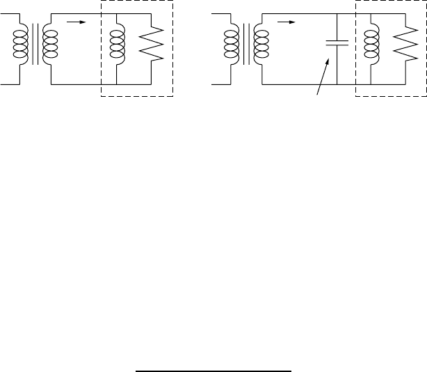
THE POWER TRIANGLE AND POWER FACTOR CORRECTION 65
(a) Original circuit (b) With PF correcting capacitor
Load,
lagging PF
Fully loaded
transformer
i
(PF < 1)
PF
correcting
capacitor
i
(PF = 1)
Load,
lagging PF
Transformer
with extra
capacity
Figure 2.10 Correcting power factor for an inductive load by adding a parallel capacitor.
gets its current from the inductance. That is, the two reactive elements, capacitor
and inductance, oscillate, sending current back and forth to each other.
Capacitors used for power factor compensation are rated by the volt-amps-
reactive (VAR) that they supply at the system’s voltage. When rated in these
units, sizing a power-factor correcting capacitor is quite straightforward and is
based on the kVAR of a capacitor offsetting some or all of the kVAR in the
power triangle.
Example 2.7 Avoiding a New Transformer by Improving the Power Factor.
A factory with a nearly fully loaded transformer delivers 600 kVA at a power
factor of 0.75. Anticipated growth in power demand in the near future is 20%.
How many kVAR of capacitance should be added to accommodate this growth
so they don’t have to purchase a larger transformer?
Solution. At PF = 0.75, the real power delivered at present is 0.75 × 600 kVA =
450 kW. And the phase angle is θ = cos
−1
(0.75) = 41.4
◦
. If demand grows by
20%, then an additional 90 kW of real power will need to be supplied. At that
point, if nothing is done, the new power triangle would show
Real power P = 450 + 90 = 540 kW
Apparent power S = 540 kW/0.75 = 720 kVA (too big for this transformer)
Reactive power Q = VI sin θ = 720 kVA sin(41.4
◦
) = 476 kVAR
For this transformer to still supply only 600 kVA, the power factor will have to
be improved to at least
PF = 540 kW/600 kVA = 0.90
66 FUNDAMENTALS OF ELECTRIC POWER
The phase angle now will be θ = cos
−1
(0.90) = 25.8
◦
. The reactive power will
need to be reduced to
Q = 600 kVA sin 25.8
◦
= 261 kVAR
The difference in reactive power between the 476 kVAR needed without power
factor correction and the desired 261 kVAR must be provided by the capaci-
tor. Hence
PF correcting capacitor = 476 − 261 = 215 kVAR
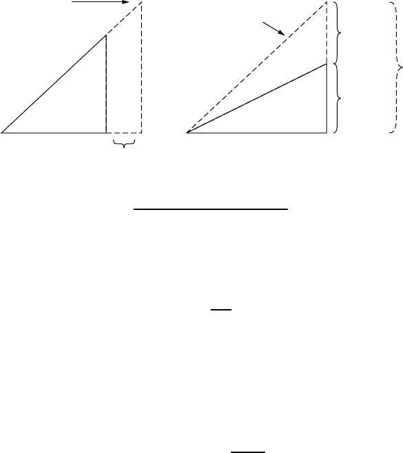
The power triangles before and after PF correction are shown below:
q = 41.4°
P
= 450 kW
Q
= 397 kVAR
S
= 600 kVA
S
= 600 kVA
P
= 540 kW
261 kVAR
q = 25.8°
(a) Before correction (b) With 215-kVAR capacitor
Q
′= 476 kVAR
Q
′= 476 kVAR
90 kW
Anticipated
growth to 720 kVA
Without
PF correction
215-kVAR
Capacitor
While rating capacitors in terms of the VAR they provide is common in power
systems, there are times when the actual value of capacitance is needed. From
(2.24), we have a relationship between current through a c apacitor and voltage
across it:
V =
1
ωC
I(2.24)
The power through a capacitor is all reactive, so that
VA R = VI = V(ωCV) = ωCV
2
(2.45)
That is, the conversion from VARs to farads for a capacitor is given by
C(farads) =
VA R s
ωV
2
(2.46)
Notice, by the way, that the VAR rating of a capacitor depends on the square of
the voltage. For example, a 100-VAR capacitor at 120 V would be a 400-VAR

THREE-WIRE, SINGLE-PHASE RESIDENTIAL WIRING 67
reactance at 240 V. That is, the VAR rating itself is meaningless without knowing
the voltage at which the capacitor will be used.
Example 2.8 Power-Factor-Correcting Capacitor for a Motor What size
capacitor would be needed to correct the power factor of the 230-V, 60-Hz, 5-hp
motor in Example 2.6?
Solution. The capacitor must provide 4.40 kVAR of capacitive reactance to cor-
rect for the motor’s 4.40 kVAR of inductive reactance. Since this is a 230-V
motor operating at 60 Hz, (2.46) indicates that the capacitor should be
C =
VA R s
ωV
2
=
4400
2π × 60 × (230)
2
= 0.000221 F = 221 µF
2.5 THREE-WIRE, SINGLE-PHASE RESIDENTIAL WIRING
The wall receptacle at home provides single-phase, 60-Hz power at a nominal
voltage of about 120 V (actual voltages are usually in the range of 110–120 V).
Such voltages are sufficient for typical, low-power applications such as light-
ing, electronic equipment, toasters, and refrigerators. For appliances that requires
higher power, such as an electric clothes dryer or an electric space heater, special
outlets in your home provide power at a nominal 240 V. Running high-power
equipment on 240 V rather than 120 V cuts current in half, which cuts i
2
R heat-
ing of wires to one-fourth. That allows easy-to-work-with, 12-ga. wire to be
used in a household, for both 120-V and 240-V applications. So, how is that
240 V provided?
Somewhere nearby, usually on a power pole or in a pad-mounted rectan-
gular box, there is a transformer that steps down the voltage from the utility
distribution system at typically 4.16 kV (though sometimes as high as 34.5 kV)
to the 120 V/240 V household voltage. Figure 2.11 shows the basic three-wire,
single-phase service drop to a home, including the transformer, electric meter,
and circuit breaker panel box.
As shown in Fig. 2.11, by grounding the center tap of the secondary side of
the transformer (the neutral, white wire), the top and bottom ends of the windings
are at the equivalent of + 120 V and − 120 V. The voltage difference between
the two “hot” sides of the circuit (the red and black wires) is 240 V. Notice the
inherent safety advantages of this configuration: At no point in the home’s wiring
system is the voltage more than 120 V higher than ground.
The ± 120-V lines are 120 V (rms) with a 180
◦
phase angle between them. In
fact, it would be reasonable to say this is a two-phase system (but nobody does).