Zhang K., Li D. Electromagnetic Theory for Microwaves and Optoelectronics
Подождите немного. Документ загружается.

5.3 Waveguides and Cavities in Rectangular Coordinates 251
-2000 -1500 -1000 -500 0 500 1000 1500 2000
0
20
40
60
80
100
E
k
b = 4.32 mm
a = 10.67 mm
f (GHz)
TE
20
TE01
TE11 TM11
TE30
TE21 TM21
E
(rad/m)
TE
10
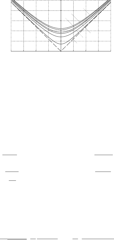
Figure 5.8: Dispersion curves (f - β diagram) of a rectangular waveguide.
In a square waveguide, for which a = b, the cutoff frequency of the TE
10
mode is equal to that of the TE
01
mode, and they are degenerate modes,
which are polarized waves perpendicular to each other. Hence the bandwidth
of single mode transmission in a square waveguide is zero, and the square
waveguide is not applied in practice.
(4) Power Flow and Attenuation Coefficient
The power flow in the rectangular waveguide can be derived from the expres-
sions (5.13) and (5.14) by substituting the functions V , (5.39), and U, (5.53),
into them,
P
TE
=
T
2
ωµβ
2
Z
a
0
Z
b
0
V
2
0
cos
2
(k
x
x) cos
2
(k
y
y) dx dy =
abkβT
2
η
2δ
m
δ
n
V
2
0
, (5.60)
P
TM
=
T
2
ω²β
2
Z
a
0
Z
b
0
U
2
0
sin
2
(k
x
x) sin
2
(k
y
y) dx dy =
abkβT
2
8η
U
2
0
, (5.61)
where η =
p
µ/²,
δ
m
=
½
1 m = 0,
2 m 6= 0,
and δ
n
=
½
1 n = 0,
2 n 6= 0.
Substituting the expressions for the magnetic field components for the TE
and TM mo ds, (5.43), (5.44), (5.45), (5.57), and (5.58), and the above two
expressions for power flows into (5.18), we have the attenuation coefficients
for the TE and TM modes:
α
TE
=
R
S
η
p
1−T
2
/k
2
·
T
2
k
2
δ
n
a + δ
m
b
ab
+
µ
1−
T
2
k
2
δ
m
n
2
a + δ
n
m
2
b
n
2
a
2
+ m
2
b
2
¸
[Np/m],
(5.62)
252 5. Metallic Waveguides and Resonant Cavities
0 1 2 3 4 5 6
0.0
.2
.4
.6
.8
1.0
1.2
1.4
1.6
TE11
TE10
TE20
TM11
TM22
c
ff
2123
VD
a
2
b
a
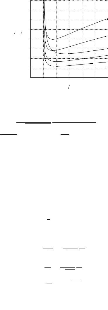
Figure 5.9: Normalized attenuation coefficients for a rectangular waveguide.
α
TM
=
2R
S
η
p
1 − T
2
/k
2
n
2
a
3
+ m
2
b
3
ab (n
2
a
2
+ m
2
b
2
)
[Np/m], (5.63)
where R
S
=
p
ωµ/2σ = 1 /σδ, η =
p
µ/². Plots of the attenuation co effi-
cients for some lower modes in a rectangular waveguide are shown in Fig-
ure 5.9.
(5) The Dominant Mode, TE
10
For a waveguide, the mode with the lowest cut-off frequency, i.e., the lowest
mode is defined as the dominant mode or principal mode. The dominant
mode of a rectangular waveguide is the TE
10
mode, if a > b.The cutoff phase
coefficient of the TE
10
mode in a rectangular waveguide is obtained from
(5.37), with m = 1, n = 0,
k
x
= T =
π
a
, k
y
= 0. (5.64)
The cutoff frequency and the cutoff wavelength are
ω
c
=
T
√
µ²
=
1
√
µ
r
²
r
πc
a
, (5.65)
f
c
=
ω
c
2π
=
1
√
µ
r
²
r
c
2a
, (5.66)
λ
c
=
c
f
c
= 2a
√
µ
r
²
r
. (5.67)
When the waveguide is filled with vacuum or air, they become
ω
c
=
πc
a
, f
c
=
c
2a
, λ
c
= 2a. (5.68)
5.3 Waveguides and Cavities in Rectangular Coordinates 253
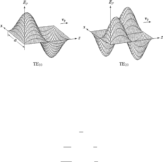
Figure 5.10: Curved surfaces of the instantaneous E
y
for TE
10
and TE
20
modes in a rectangular waveguide.
The field comp onents of the TE
10
mode are obtained from (5.40)–(5.45), with
m = 1, n = 0:
E
y
= E
0
sin
³
π
a
x
´
e
−jβz
, (5.69)
H
x
= −
β
ωµ
E
0
sin
³
π
a
x
´
e
−jβz
, (5.70)
H
z
= j
π
ωµa
E
0
cos
³
π
a
x
´
e
−jβz
, (5.71)
E
x
= 0, E
z
= 0, H
y
= 0,
where E
0
= −jωµ(π/a)V
0
.
The field map of the TE
10
mode is shown in Fig. 5.5. The curved surfaces
of the instantaneous values of E
y
(x, z) for TE
10
and TE
20
modes are plotted
in Fig. 5.10.
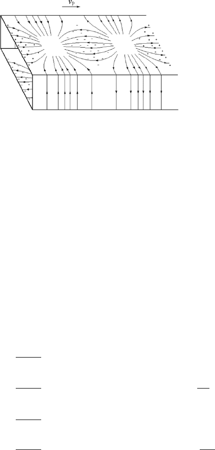
The surface charge density and the surface current density on the inner
wall of the waveguide may be obtained from the boundary conditions given in
Section 1.2.2. The map of the surface charge density and the surface current
density for the TE
10
mode is given in Fig. 5.11. It can be seen that the
surface conduction current on the wall is continuous with the displacement
current in the waveguide.
(6) LSE and LSM Modes in Rectangular Waveguides [37]
The classification of TE and TM modes with respect to z is important and is
applied to cylindrical waveguides with any cross section. However, for many
rectangular waveguide problems, other convenient classifications can be made
and we can have alternative mo de sets.
We have mentioned in Section 4.7 that for rectangular coordinates, we
may choose x or y rather than z as the special coordinate u
3
, and the fields
254 5. Metallic Waveguides and Resonant Cavities
Figure 5.11: Surface charge density and surface current density on the inner
wall for the TE
10
mode in a rectangular waveguide.
are expressed by TE
(x)
, TM
(x)
, TE
(y )
and TM
(y )
modes. They are also
denoted by LSE
(x)
, LSM
(x)
, LSE
(y )
and LSM
(y )
modes, respectively, because
the electric field or the magnetic field is distributed on a longitudinal section
perpendicular to the x or y coordinate. From this viewpoint, the ordinary
TE and TM modes are actually TE
(z)
and TM
(z)
modes.
(a) LSE
(x)
Modes or TE
(x)
Modes
For LSE
(x)
modes, E
x
= 0, U
(x)
= 0. The general expression for V
(x)
is
V
(x)
= A sin(k
x
x + φ) cos(k
y
y + ψ)e
−jβz
, (5.72)
Considering (4.153)–(4.158), the boundary conditions on the walls are
E
z
|
y =0
= jωµ
1
∂V
(x)
∂y
¯
¯
¯
¯
y =0
= 0, sin ψ = 0, ψ = 0,
E
z
|
y =b
= jωµ
1
∂V
(x)
∂y
¯
¯
¯
¯
y =b
= 0, sin k
y
b = 0, k
y
=
nπ
b
,
E
z
|
x=0
= jωµ
1
∂V
(x)
∂y
¯
¯
¯
¯
x=0
= 0, sin φ = 0, φ = 0,
E
z
|
x=a
= jωµ
2
∂V
(x)
∂y
¯
¯
¯
¯
x=a
= 0, sin k
x
a = 0, k
x
=
mπ
a
.
Functions V
(x)
becomes
V
(x)
= A sin(k
x
x) cos(k
y
y)e
−jβz
, (5.73)
where k
x
= mπ/a and k
y
= nπ/b are the same as those for ordinary TE and
TM modes.

5.3 Waveguides and Cavities in Rectangular Coordinates 255
Substituting it into (4.153)–(4.158), we obtain the field-component ex-
pressions for LSE
(x)
modes
E
x
= 0, (5.74)
E
y
= −jωµ
∂V
(x)
∂z
= −ωµβA sin(k
x
x) cos(k
y
y)e
−jβz
, (5.75)
E
z
= jωµ
∂V
(x)
∂y
= −jωµk
y
A sin(k
x
x) sin(k
y
y)e
−jβz
, (5.76)
H
x
=
¡
k
2
− k
2
x
¢
V
(x)
=
¡
k
2
− k
2
x
¢
A sin(k
x
x) cos(k
y
y)e
−jβz
, (5.77)
H
y
=
∂
2
V
(x)
∂y ∂x
= −k
x
k
y
A cos(k
x
x) sin(k
y
y)e
−jβz
, (5.78)
H
z
=
∂
2
V
(x)
∂z ∂x
= −jβk
x
A cos(k
x
x) cos(k
y
y)e
−jβz
. (5.79)
We can see from the field expressions that, for LSE
(x)
modes, if k
x
= 0,
then all field components become zero, so k
x
cannot be zero, while k
y
can
be zero. This kind of modes with k
y
= 0 are LSE
(x)
m0
modes. Comparing
the above expressions with the expressions for ordinary TE modes (5.40) to
(5.45), we see that the LSE
(x)
m0
modes are just the TE
m0
modes. The LSE
(x)
mn
modes with n 6= 0 are all combinations of TE mode and TM mode, i.e.,
hybrid modes.
(b) LSM
(x)
Modes or TM
(x)
Modes
For LSM
(x)
modes, H
x
= 0, V
(x)
= 0. After using the boundary condi-
tions, the expression for U
(x)
can be given by
U
(x)
= B cos(k
x
x) sin(k
y
y)e
−jβz
, (5.80)
where k
x
= mπ/a and k
y
= nπ/b.
Substituting it into (4.153)–(4.158), we may obtain the field component
expressions for LSM
(x)
modes
E
x
=
¡
k
2
− k
2
x
¢
U
(x)
=
¡
k
2
− k
2
x
¢
B cos(k
x
x) sin(k
y
y)e
−jβz
, (5.81)
E
y
=
∂
2
U
(x)
∂y ∂x
= −k
x
k
y
B sin(k
x
x) cos(k
y
y)e
−jβz
, (5.82)
E
z
=
∂
2
U
(x)
∂z ∂x
= jβk
x
A sin(k
x
x) sin(k
y
y)e
−jβz
, (5.83)
H
x
= 0, (5.84)
H
y
= jωµ
∂U
(x)
∂z
= ωµβA cos(k
x
x) sin(k
y
y)e
−jβz
, (5.85)
H
z
= −jωµ
∂U
(x)
∂y
= −jωµk
y
A cos(k
x
x) cos(k
y
y)e
−jβz
. (5.86)
256 5. Metallic Waveguides and Resonant Cavities
Figure 5.12: Field maps of LSE and LSM mo des.
From the field expressions, we find that, for LSM
(x)
modes, k
y
cannot
be zero, while k
x
can be zero. This kind of modes with k
x
= 0 are LSM
(x)
0n
modes. Comparing the expressions for LSM
(x)
mn
modes with the expressions
for ordinary TE modes (5.40) to (5.45), we see that the LSM
(x)
0n
modes are
just the TE
0n
modes. The LSM
(x)
mn
modes with m 6= 0 are all combinations
of TE mode and TM mode, i.e., hybrid modes or so called HEM modes.
We come to the conclusion that, the LSE
(x)
0n
and LSM
(x)
m0
modes do not
exist; the LSE
(x)
m0
and LSM
(x)
0n
modes are just the TE
m0
and TE
0n
modes,
respectively, they are not only transverse electric modes but also longitudinal
section modes.
We have seen that the TE
(z)
mn
mode and TM
(z)
mn
mode are degenerate
modes with the same propagation characteristics. The linear combination of
the degenerate TE and TM modes with the same m and the same n forms
new hybrid modes, which are just the LSE
(x)
mn
and LSM
(x)
mn
modes with both
nonzero m and n.
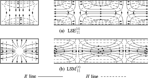
The field map of the LSE
(x)
11
and LSM
(x)
11
modes are shown in Fig. 5.12,
they are the combinations of TE
11
and TM
11
modes.
The LSE
(y )
and LSM
(y )
modes can also be analyzed by means of the
similar process.
5.3.2 Parallel-Plate Transmission Lines
In the parallel-plate transmission line, shown in Figure 5.13, if the space a
between two plates is much less than the width w, the fields will be uniform
along the direction of the width y. The parallel-plate transmission line con-
sists of two insulated conductors, hence the TEM mode can exist in it. It is
a good example that we can deal with it by means of either circuit theory or
field theory.
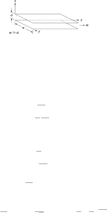
5.3 Waveguides and Cavities in Rectangular Coordinates 257
Figure 5.13: Parallel-plate transmission line.
(1) TE and TM Modes
With the short-circuit boundary conditions applied to the planes x = 0 and
x = a, the field components of the TE
m
and TM
n
modes are given as follows:
TE modes, E
x
= 0, E
z
= 0, H
y
= 0, and
E
y
= E
0
sin k
x
x e
−jβz
(5.87)
H
x
= −
E
0
η
TE
sin k
x
x e
−jβz
, (5.88)
H
z
= j
k
x
β
E
0
η
TE
cos k
x
x e
−jβz
, (5.89)
TM modes, E
y
= 0, H
x
= 0, H
z
= 0, and
E
x
= E
0
cos k
x
x e
−jβz
, (5.90)
E
z
= j
k
x
β
E
0
sin k
x
x e
−jβz
, (5.91)
H
y
= −
E
0
η
TM
cos k
x
x e
−jβz
, (5.92)
where
k
x
=
mπ
a
, m = 1, 2, 3 ······. (5.93)
The transverse angular wave numb er, cutoff angular frequency, and cutoff
wavelength of the TE and TM modes in the parallel plate line are
T = k
x
=
mπ
a
, ω
c
=
T
√
µ²
, λ
c
= 2π
c
ω
c
=
2a
m
√
µ
r
²
r
. (5.94)
The field maps of the TE and TM modes in a parallel-plate transmission
line are given in Fig. 5.14, which are the same as those for total reflection
of a plane wave on a perfect conducting plane, given in Section 2.4.2. In
fact, the waves of TE and TM modes in parallel-plate line can be seen as
the result of uniform plane wave obliquely reflected from the two conducting
plans successively.
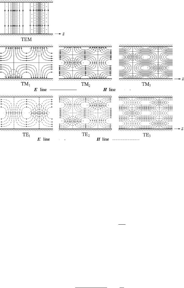
258 5. Metallic Waveguides and Resonant Cavities
Figure 5.14: Field maps in a parallel-plate transmission line.
(2) The TEM Mode
The fields of the TEM mode can satisfy the boundary conditions of the
parallel-plate transmission line, which consists of two isolated conductors.
For the TEM mode, T = 0, k
x
= k
y
= 0, and β = k. The fields in (5.87)–
(5.89) are all zero and the fields in (5.90)–(5.92) become the fields for the
TEM mode
E
x
= E
0
e
−jβz
, H
y
=
E
0
η
e
−jβz
, (5.95)
E
y
= 0, E
z
= 0, H
x
= 0, H
z
= 0.
The TEM fields in between the two plates are the same as those for a uniform
plane wave propagate along the z direction.
By using (3.70), we have the characteristic impedance of the TEM mode
in parallel plate line:
Z
C
=
R
a
0
E
0
dx
R
w
0
(E
0
/η)dy
= η
a
w
. (5.96)
The cutoff frequency of the TEM mode is zero, so the TEM mode is the
dominant mode in the parallel-plate line. The condition for the propagation
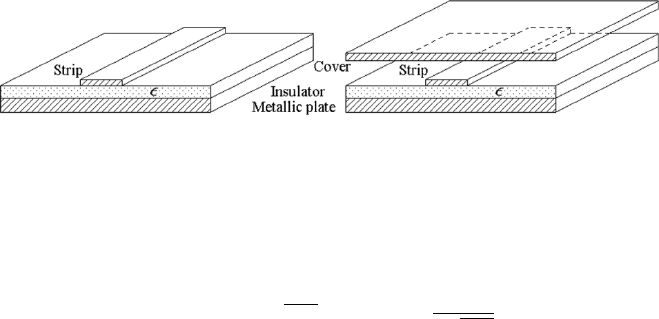
5.3 Waveguides and Cavities in Rectangular Coordinates 259
Figure 5.15: Micro-strip lines.
of a single TEM mode is that the wavelength must be larger than the cutoff
wavelength of the next lower-order modes, the TE
1
and TM
1
modes,
λ > λ
c1
= 2a
√
µ
r
²
r
, a <
λ
2
√
µ
r
²
r
. (5.97)
The modified parallel-plate lines, namely micro-strip lines showed in
Fig. 5.15 have been used in modern microwave circuits as well as microwave
integrated circuits quite intensively, because they can be fabricated by printed
circuit or microelectronic technologies. when the width of the strip is much
larger than the space b etween the strip and the substrate, micro-strip can
be approximately analyzed as a parallel-plate line. If not so, the fringe effect
must be considered by means of static field theory. In practice, there must be
an insulator on the substrate to support the strip, and the dielectric bound-
ary are to be taken into account for the analysis. The influence of a dielectric
boundary in electromagnetic wave propagation is somewhat complicate and
will be given in Chapter 6. The result is that, no absolute TEM mode exists
in a dielectric supported micro-strip line, the dominant mode used in practice
is a quasi-TEM mode, refer to literatures on microwave circuits.
5.3.3 Rectangular Resonant Cavities
The rectangular resonant cavity is a section of rectangular waveguide enclosed
by conducting plates at the two ends, z = 0 and z = l, refer to Fig. 5.16.
The short-circuit boundary conditions at the two ends, z = 0 and z = l,
can be satisfied only when two opposite traveling waves along +z and −z
exist simultaneously and form a standing wave in the z direction. Hence the
fields in a rectangular cavity are standing waves in all the three directions.
(1) TE Modes
The function U is zero and
V (x, y, z) = X(x)Y (y)Z(z)
= (A sin k
x
x + B cos k
x
x)(C sin k
y
y + D cos k
y
y)
¡
F e
jk
z
z
+ Ge
−jk
z
z
¢
. (5.98)
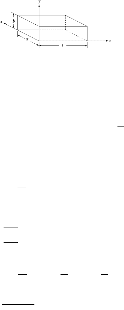
260 5. Metallic Waveguides and Resonant Cavities
Figure 5.16: Rectangular resonant cavity.
The boundary conditions on the walls at x = 0, x = a, y = 0, and y = b
are the same as those for a rectangular waveguide, and the results are given
in (5.33)–(5.36). The boundary conditions of function V on the short-circuit
surface at z = 0 and z = l are given by
V |
z=0
= 0 −→ G = −F, (5.99)
V |
z=l
= 0 −→ e
jk
z
l
− e
−jk
z
l
= 2j sin k
z
l = 0, k
z
=
pπ
l
, (5.100)
where p is an integer. Substituting (5.33)–(5.36) and (5.99) and (5.100) into
(5.98), let V
0
= 2jBDF , gives
V (x, y, z) = V
0
cos(k
x
x) cos(k
y
y) sin(k
z
z), (5.101)
The field components are given by substituting (5.101) into (4.141)–(4.146):
E
x
= −jωµ
∂V
∂y
= jωµk
y
V
0
cos(k
x
x) sin(k
y
y) sin(k
z
z), (5.102)
E
y
= jωµ
∂V
∂x
= −jωµk
x
V
0
sin(k
x
x) cos(k
y
y) sin(k
z
z), (5.103)
E
z
= T
2
U = 0, (5.104)
H
x
=
∂
2
V
∂x ∂z
= −k
x
k
z
V
0
sin(k
x
x) cos(k
y
y) cos(k
z
z), (5.105)
H
y
=
∂
2
V
∂y ∂z
= −k
y
k
z
V
0
cos(k
x
x) sin(k
y
y) cos(k
z
z), (5.106)
H
z
= T
2
V =
¡
k
2
x
+ k
2
y
¢
V
0
cos(k
x
x) cos(k
y
y) sin(k
z
z), (5.107)
where
k
x
=
mπ
a
, k
y
=
nπ
b
, k
z
=
pπ
l
.
Then the natural angular wave number and the natural angular frequency
are given by
k
mnp
=
q
k
2
x
+ k
2
y
+ k
2
z
=
r
³
mπ
a
´
2
+
³
nπ
b
´
2
+
³
pπ
l
´
2
, (5.108)